Category: General

Booms, davits and derricks, part I

There are many booms, davits, and derricks scattered around HMS Hood’s decks and superstructure. The rigging and davits are drawn up in excellent detail by John Roberts’ Anatomy of the Ship: HMS Hood and Anatomy of the Ship: HMS Dreadnought. A full list of booms and derricks is given in Maurice Northcott’s HMS Hood: Design & Construction (Ensign Special or Man o’War, same content). Together they have nearly all the information we need for the 1941 version. From the images can be concluded that some booms are tapered, but derricks are not. All booms and derricks are wooden, except the main derrick.

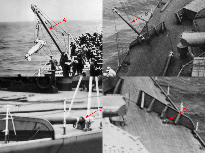
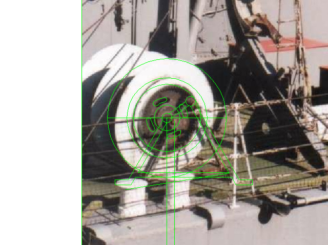
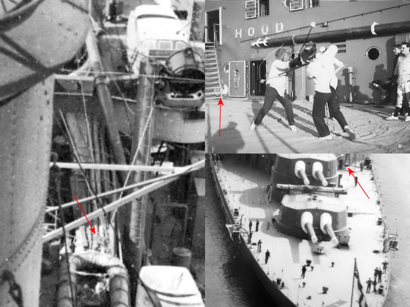
Here you can see a paravane being deployed or recovered (A), but this is not the paravane derrick. This derrick is operated next to A turret, while the actual paravane derricks were stored directly aft of the forward breakwater where a pair of paravanes were stored (B). You rarely see these derrick deployed though and if you want to add them the best option is to either model them lowered (C) or not at all (D); Most images of the forward breakwater show the derricks to be absent. So, if you build the Trumpeter kit you’d best throw these parts away.

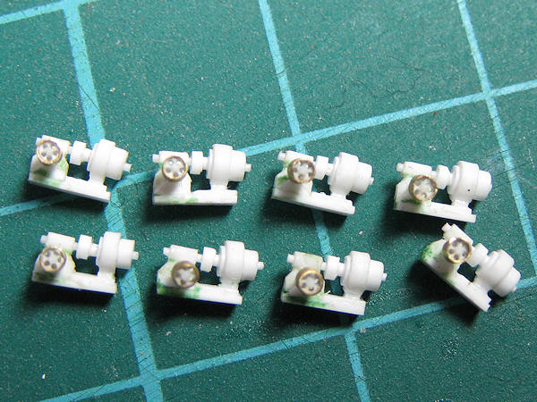
The second largest set of derricks consists of three pairs of 40ft derricks. These derricks were used to load ammunition or hoist boats. When HMS Hood was completed, one set was stored near the bridge, one set was fitted to the smaller cranes on either side of the funnels, one set was stored at the deck side on either side of the main derrick and one set was stored to the quarterdeck (4 pair). For the 1941 version, two pairs of derricks were fitted to the bridge bulkhead, below the smaller sounding booms, while the other two sets remained fitted to the smaller cranes. The quarterdeck derricks were removed.

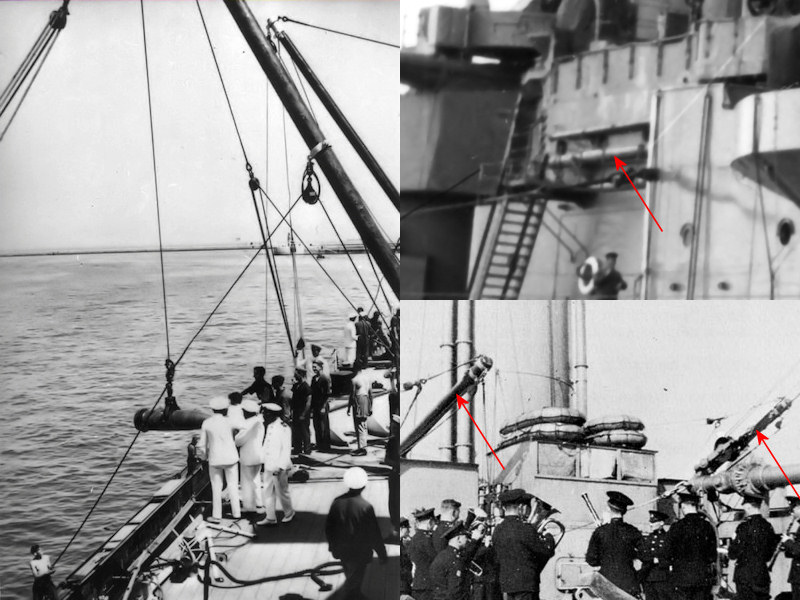
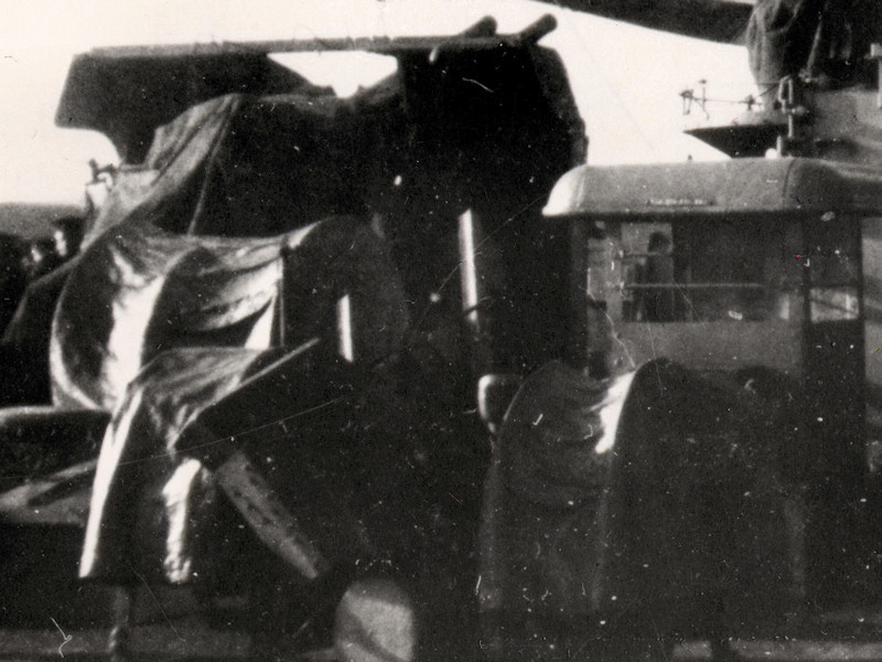
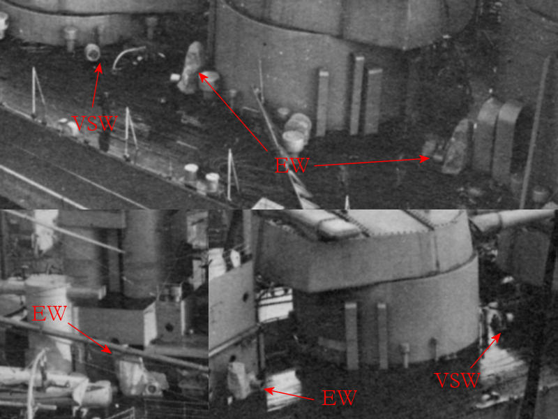
Another set are the 36′ 9″ sounding booms. No resource specifically identifies their location, but two booms of the same length were fitted above the 40ft derricks during the final modification. This indicates that the sounding machines themselves were on board when HMS Hood was sunk. The image shows the sounding boom deployed during outfitting (A). Two sets of booms are fitted for embarking and disembarking. One set of 50ft guest warp booms (A) was fitted to the hull near the bridge and one set of 30ft6in swinging booms was fitted at the quarterdeck bulkhead. These booms were all tapered. Note how all these booms were rigged with a stay and two lines.

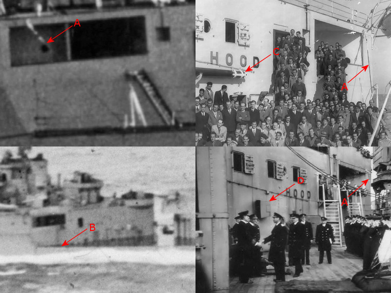
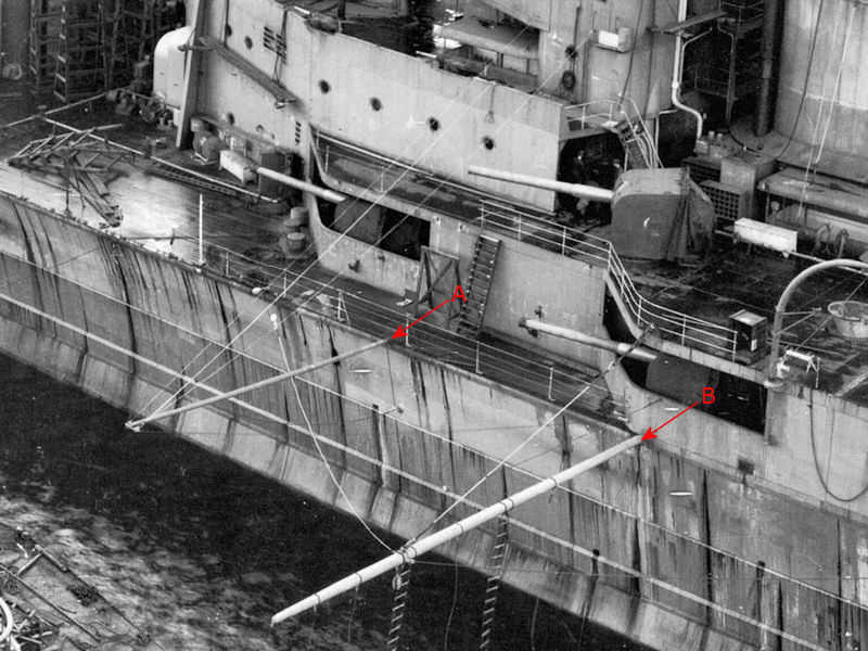
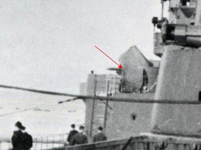
The swinging boom near the quarterdeck bulkhead is very difficult to spot in photographs taken during the war. The stays are easier to spot (A), even though the boom is not (B). Note that the 40ft ammunition derrick at (C) was removed when the air intake in the quarterdeck bulkhead was covered up (D). The stay for the swinging boom is still present in the image bottom right.

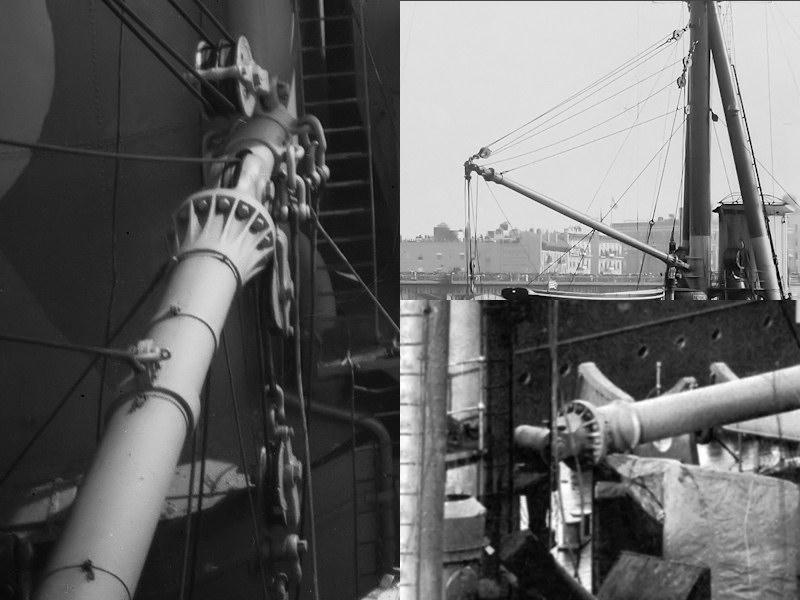
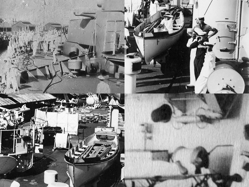
The largest derrick is of course the main derrick operated from the main mast. Here you can seen the main derricks aboard HMS Rodney (left), HMS Inflexible (top right) and HMS Hood (bottom right). The style of the main derrick appears the same for all capital ships and the drawing in the Anatomy of the Ship: HMS Hood is not accurate. There are small changes in the rig of the derrick between ships and the hoist line does not loop back the same number of times for all ships.

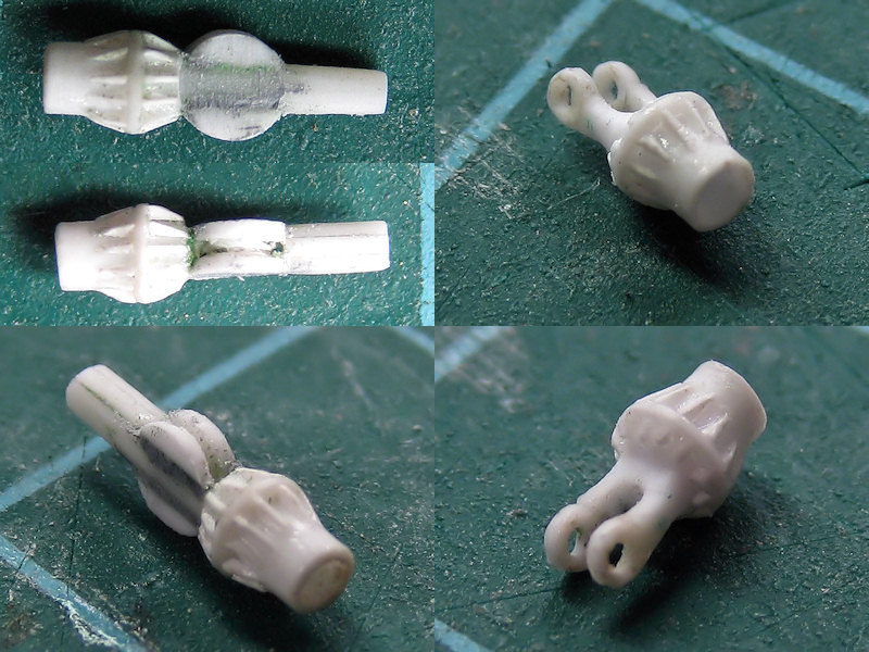
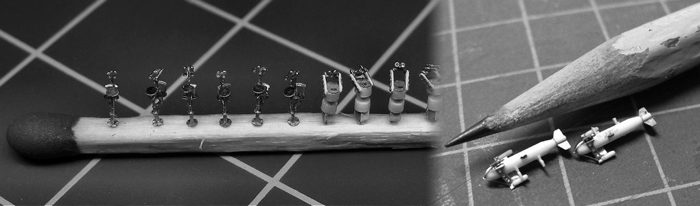
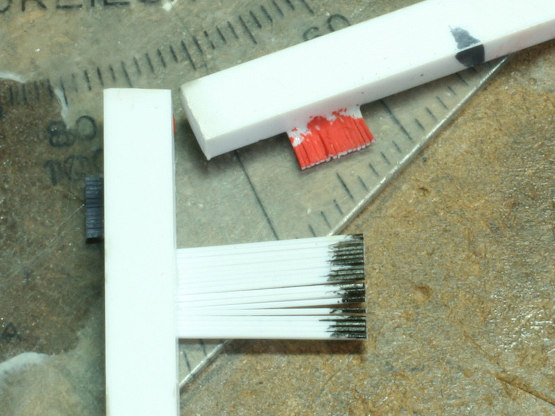
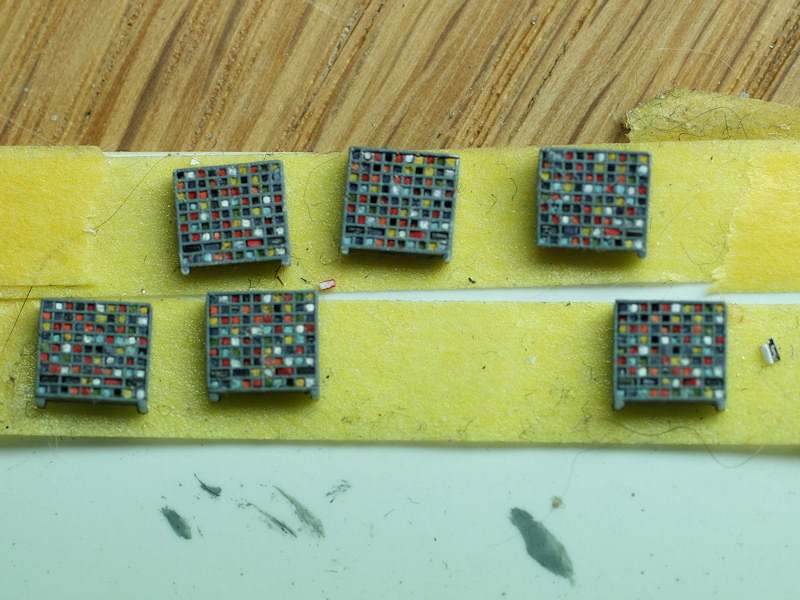
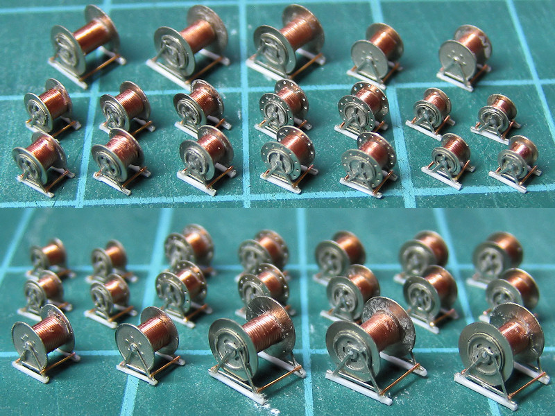
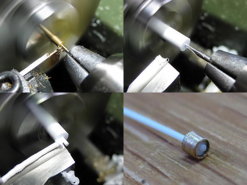
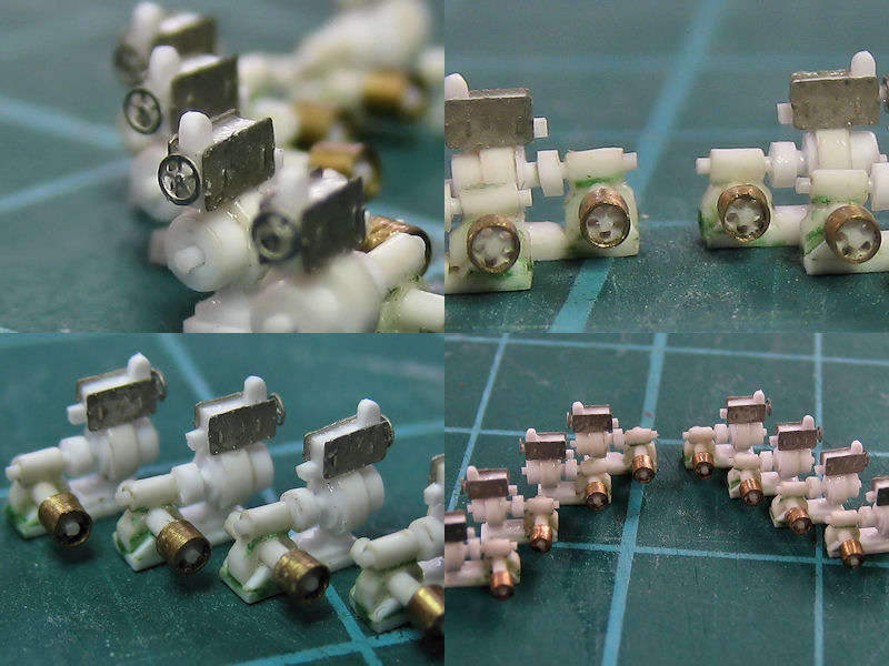
The flange couplings of the main derrick were simulated with tiny triangles added with a very fine pair of tweezers. The pully in the end of the derrick was added as well for proper rigging. The start point of the derrick was ‘milled’ into shape with the cross table of the drill press.

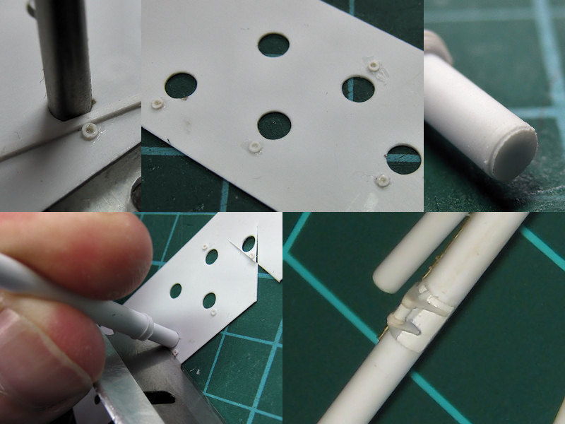
The support on the main mast was built from plastic plate; you don’t always need photo-etch to make such difficult to make shapes (even though I should have).

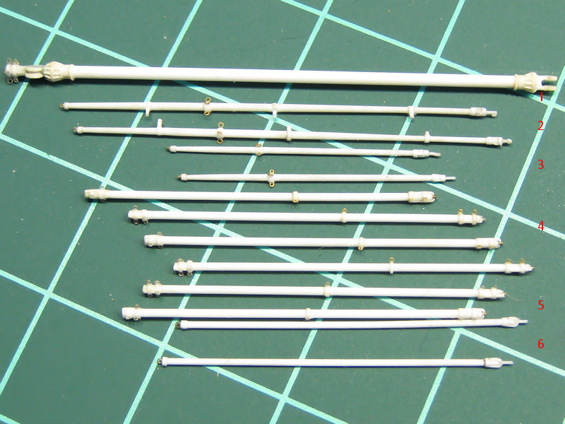
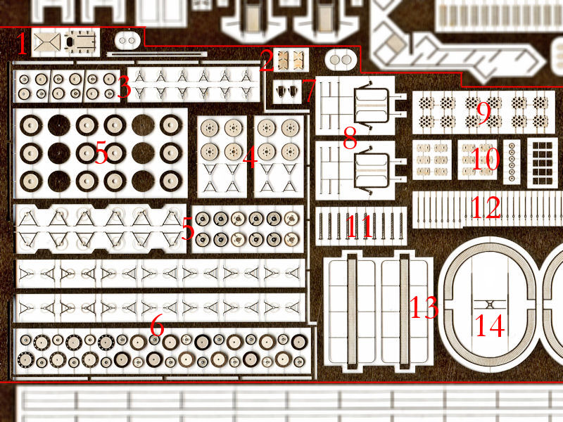
The list comprises of

1 65ft main derrick (1)

2 50ft guest warp booms (2)

2 30ft 6″ swinging booms (3)

4 40ft 4t ammunition derricks (4)

2 40ft 5t boat & ammunition derricks (small cranes) (5)

2 36ft 6in sounding booms (6)

2 12ft paravane derricks, mostly stored

Northcott lists one 8ft derrick present as late as 1931, but I haven’t been able to find any image, so I guess it was stored out of sight with the paravane derricks?

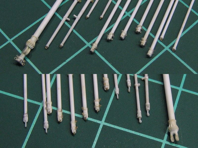
Most work on the derricks was spent adding small rings!

The smaller davits will be treated in a small follow-up post.


Flag Lockers

This is a nice image from the Seaman’s pocket book of a few flags used by the signalmen, reproduction of the 1943 version. I thought it would be a nice idea to add some colours to the flag lockers.

Here’s a pic I took of HMS Belfast’s flag locker. The text on the top row is hidden in this image but reads P1 to P9 plus P0 for a few naval pendants. Most ships carried several of these lockers and images of HMS Hood before her final reconstruction show as many as 6 flag lockers, afterwards at least 4. The HMS Hood site even shows a flag locker in the wreckage but of a different type, which I cannot trace to any location at the moment. I did find images of the four flag lockers of the standard type as on HMS Belfast.

These are the small models. Note the larger openings on the one-but-lowest row. They worked out quite nicely (which isn’t a surprise as these are the second version after ironing out a few minor design errors).

Here you can see what flag goes what cell of the locker. As each cell is about 0.3 by 0.3 mm there is no room to paint anything but solid colour.

So I made a small colour map with the dominant colour. Yellow & red flags become orange, green & white light green, blue & white light blue, blue & yellow become green. Red & white may become pink so I decided they are folded such that only one colour shows. If adjacent colours are the same the flag will be ‘folded’ differently as well to keep the appearance of variation; the flags with more than two colours allowed for some variation.

I prepared some styrene strip (Plastruct) and added some colour. Here you can see blue, red, and black ‘flags’. These are for the one-but-lowest row, wide openings. For the other flags I painted the tip of the strips. These were cut to size with the chopper and inserted with tweezers. Sometimes they didn’t fit and had to be removed. Sometimes they could only be removed by drilling them in with a 0.3mm drill and carefully removing what’s left. I had one drill broken and the tip couln’t be removed; the end of that flag locker. As the strip/rod of Plastruct or Evergeen is never exactly constant in its dimensions, some strips fit better than others so they were fixed with a drop of varnish. More strips lie on the floor than fit in the lockers. T His was a good reason to stop my attempt to add some striping to the ‘flags’ to add even more detail.

The flag lockers were taped with their backs to styrene sheet and filled carefully. Minor damage to the base coat of the lockers is visible but I like the result. These will be added to the model after general painting to avoid embarrassing errors with masking…

Cordage and Hawser reels, Part I

One of the reasons this blog wasn’t updated for a quarter of a year was due to the trouble I had with assembling the cordage and hawser reels. I’ve split up the posts into two parts: standing and hanging reels. The latter are the thinner reels that are scattered around HMS Hood hanging from a bulkhead (about fifteen) plus the four smaller reels near the davits of the 27″ whalers. Here I’ll show the standing hawser and cordage reels, otherwise known as the opening scene of “how I started worrying and learned to hate my model”.

One of the things that will immediately become apparent when you start looking for photographs is that the reels are nearly always covered in canvas (just as the ships boats). Although I want to have the most accurate model I can build, I already decided to slightly cheat on those covers so that all detail would be there to admire. Using the images that I had, I started with a head count. This is quite difficult, as you need to determine the height of each reel correctly before you can decide what type it is, or perhaps you find out it is a type you missed? I certainly wouldn’t recommend estimating the type by eye, I really needed a ruler the estimate the dimensions in relation to items in each photograph.

I’ve identified five types. The first type is the large hawser reel (L) that is specified in the Anatomy of the Ship series volume (but not entirely to my liking). I found one behind the forward breakwater, two on either side of the aft searchlight platform, and one next to the bridge (see below).

Other types are seen here. The top right one is a cordage reel that remained on board HMS Hood, but I cannot find more that one, at the starboard side of the forward funnel. The bottom-left is a hawser reel that is similar to the largest hawser reel but smaller, about the height of the railing (hence medium). I found six so far: one behind the forward breakwater, two behind B-barbette, two in front of the main stairs on the boat deck (between and outboard of the funnels), one near the main mast. I also had a look at the image top left and decided this cordage had a few weight-saving holes. This is not uncommon so I made a variant on the medium hawser reel. I now think it’s just a normal cordage as the one top right and the image is too poor to make out its correct configuration. Still, these variants were added anyway. We know that many cordage reels were replaced by hawser reels so this one will be a hawser reel too. The last type is a hawser reel shown bottom left that is basically too small to be a medium hawser reel (so: small). There are four: two are fitted below the paravanes stored on either side of the bridge (lots of smaller reels are fitted there as well), and two were found at the far end of the boat deck, both at port side.

This image shows two small and one large reels at the far end of the boat deck. The right vent and 4″ mount serves as a reference for identifying them.

This image shows a nice surprise: there is a large hawser reel (taller than the railing) fitted near the bridge. There are no other images of this reel, so it’s quite difficult to make out its position.

The dimensions were obtained from careful observation, but the pattern followed from tracing existing reels from museum ships. This image was taken of HMS Haida, taken from Resin Shipyards, with permission. The design matches the drawing in Anatomy of the Ship and required dimensions nicely.

The other reels were drawn using what material I had. In order not too have too few details on these parts—can’t have that—I decided that each side of the reel should consist of three parts, as shown here. There are a few design choices I made that seemed like a wonderful idea but turned out to be quite to opposite. The center part would first be glued to the large part, by applying glue from behind. The combined parts would then be centered on a small drill and the last part would be added, nicely centered. I started with the largest reels, thinking them easiest to construct but they were the hardest to do by far. Notice that the center etch part has a small circle that fits nicely on the part at right? These need to be aligned. This was the first major error: it is so very difficult to apply glue while keeping the parts aligned. I’ll make sure to avoid breaking rotational symmetry of the parts when I can help it.

But this was only the beginning of my troubles. The parts are etched in steel—not brass—that material is very difficult to glue. All parts kept falling apart and proved to be very difficult to glue back without overdoing the glue or damaging the parts. I had to try out all different types of glue before deciding on one glue that worked quite well: a good bond, not too thick, not too expensive and easy to apply. I now use ordinary Pattex. I trashed all my other super glues and I won’t be buying these miracle glues on modeling shows as they clearly suck (no, the glues!). The Pattex won’t last very long when opened, so I bought many bottles. I also learned that flat PE parts squeeze most glue to the edges, so very little glue is actually between the parts. Removing excess glue usually results in not having any glue at all. Next time I’ll etch some ridges to keep the glue where it is supposed to go.

After having solved the 2010 glue crisis, I made the drums. Simple rod with a 0.3mm hole in the center. I used thin brass wire, set my lathe to the slowest setting, and applied a bit of glue. Turn on the lathe, and see how wonderful the wire will wind itself into impossible shapes and how the glue will get everywhere and forcing you to start all over. Again! Needless to say, I had a lot of failed parts. The next problem presented itself when you find out that you need to trim the drums to length so that the edges are perpendicular to the center line; otherwise these nice etched parts will be skewed and all effort was for nothing. Of course, when the bond of previously-etched parts wasn’t as good as you hoped for, the entire part could come loose at the last minute anyway. So, at the end of the construction phase, a small round of non-destructive testing was introduced to sift the strong from the weak parts. Those who could be saved went to the depressingly small pile of finished parts.

Here they are. Nineteen small models (short of one large reel). You’ll notice that the etch set, which I had made three times, has enough parts to make ninety (link). I thought I had enough parts to make lots and lots of parts and worry about how many I needed later. “I can always choose the ones that worked out best”. Unfortunately, I hardly have spare parts left! I have one spare cordage and four medium cordage reels that are probably wrong anyway. Still, I really like the those small holes and I think I’ll scatted them around the forward gun turrets.

So, on to the really small hawser reels. The good news is: only two etched part per reel and not six.

Happy ending in part II

Winches, Part I

Two types if winches were present, the variable speed winch (VSM) and the electric winch (EW). These winches are scattered mainly around the barbettes and the forward boat deck area for the boat derricks.

The above image shows HMS Hood shortly after her construction with both types of winch clearly visible. There are two VSWs between the forward and aft turret pairs plus two more on the starboard quarterdeck . Two EWs are placed at B-barbette, two on either side on the conning tower, two near the boat derricks, and two against the quarterdeck bulkhead. The winches near the turrets aren’t positioned symmetrically, so not all winches are shown on the above photograph.

If you look very closely, you’ll notice that the rigging of the boat cranes was changes at the end of Hoods career. Two winches were placed on the structure between the funnels as indicated above (reconstructed winch shown). All (most?) references indicate these winches are the same winches as previously placed on deck level but changed position. But then there would be no winch to drive the derrick, only the hook, and the rigging scheme no longer makes sense: these have to be new winches to operate the derricks. Images showing both in a single shot weren’t found.

The evidence is really staring you in the face if you look closely at the above photograph from the official HMS Hood site of these two sailors posing in front of the boat derrick’s EW. The 16″dinghy stowed to the bulkhead and the 25″ fast motor boat indicate this picture was taken after the winches were placed between the funnels and yet a winch remains visible. So, the number of EWs was increased to ten, though only eight models are required.

The left half of the image shows how the rigging of the boat derricks was lead to these new winches. The right half of the image shows that the two EWs on the quarterdeck were later moved inside and only the drums remain visible. No small wonder, considering that Hoods quarterdeck was always flooded when underway. Having the winches inside isn’t new, all the Queen Elizabeth battleships have their winches inside.

After having done a thorough head counter the two types of winches were traced using a CAD program. Some perspective is always present but they should be reasonably accurate. The VSWs still remain a bit of a guess though.

The main difficulty in making the winches are the drums. I spent many hours trying the get the lathe to do what I wanted and made many failed attempts. The drum was made from brass stock. made flush and the center was marked. A 1.0mm hole was drilled in next. The lathe was set to make a tube with a wall thickness of 0.1mm. The lathe was set at its maximum rpm.

The tube was parted from the stock brass using a parting tool bought from MicroMark and ground to a 0.4mm width as visible top left. Note I use the drill to support to tube while parting. Although I broke a few drills while experimenting (parting tool not set at the correct height), there really was no way to get a good tube without supporting it, otherwise the lathe tears the tube from the rod. This exercise was repeated for the styrene insert, drilled in with a 0.4mm drill, cut to size and fitted with stock styrene rod.

The next part proved to be very troublesome: I wanted to have 5 holes in the drum, spaced out at 72 degrees. I initially glued the brass tube to stock styrene by Plastruct, but small deviations in its roundness made this a futile effort. The rod was simply not accurate enough and I spent many hours and breaking many drills getting the part right. When using rod made to size with the lathe, I had no such problems and the five holes could be drilled in. I set the drill press to a high rpm and mounted the drum on the divider (Proxxon). You have to be really careful here, as the drill can occasionally push the styrene our and you can also crush the drum with ease in the chuck. Of course, this happened a few times.

Eight drums are now sitting comfortably in the EWs. The winches are built from mainly lathed parts.

Here you can see the completed EWs, with the etched parts for the control box and the some hand wheels. A nice exercise in getting to know the lathe better.

Copyright © 2024 On The Slipway

Theme by Anders NorenUp ↑