Making a large full-hull model of a large model is one thing, making very small boats and launches is another and requires a different approach. You can hollow out small hulls or batter a sheet of metal against a plug, both with nice results. I chose to use vacuum forming, as it is repeatable and the hull is now from styrene which is easy to handle. My simple vacuum former was explained earlier here.
With a technique ready to be used for small hulls, the only thing left to build are the hulls themselves. After having spent some time tracking down the hull lines of all but two of HMS Hood’s boats and launches at the time of her sinking, I decided to make them all to scale with correct hull forms to match. Some of the pics I show you are already quite old and bad. At the time of this writing, most models are nearing a state of completion but are not quite ready yet.
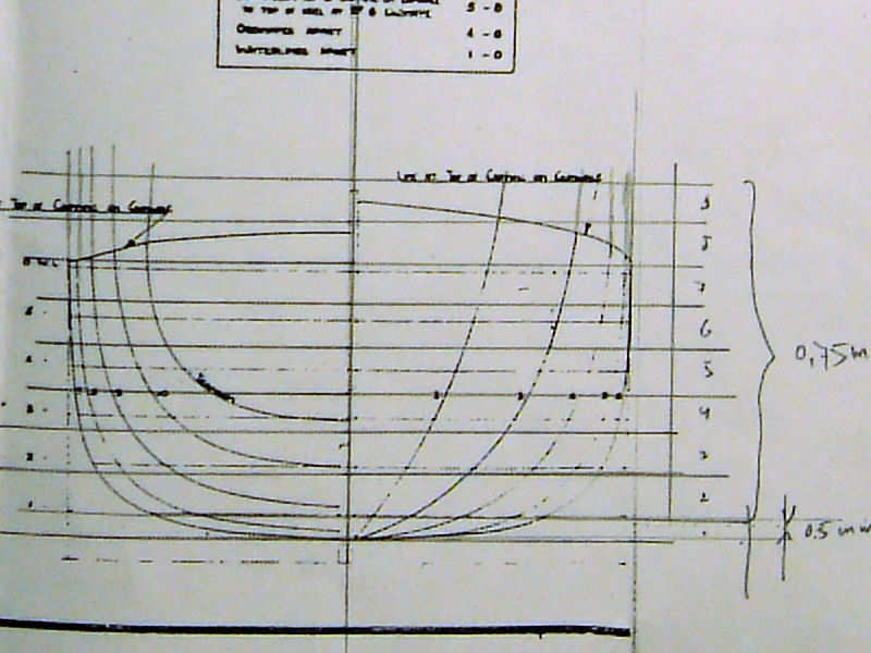
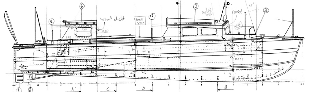
This is a bad picture of the lines drawing of the 45ft motor launch. I’ve drawn a grid with plate thicknesses to scale, in this case 0.75mm and 0.50mm. When the lines are mostly vertical you can do with thicker strips. Near the bottom of the launch, the lines change quickly and thinner plates are required. These points were measured and put into a spreadsheet, for which I use Microsoft Excel.
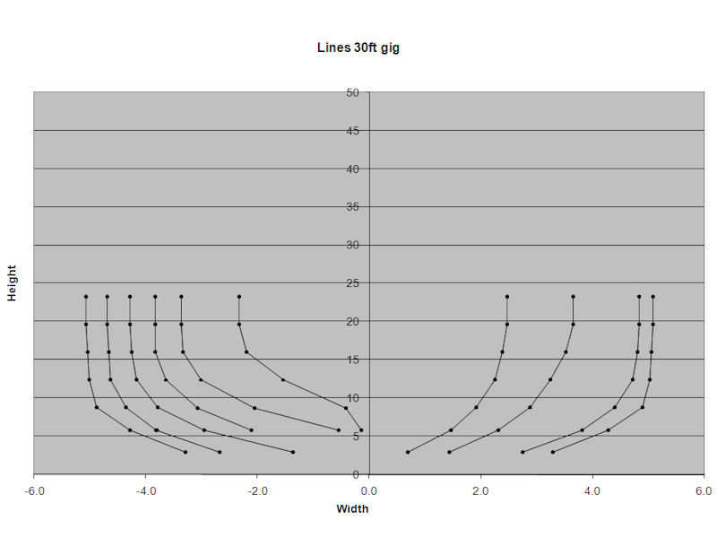
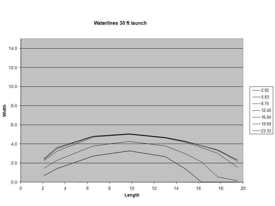
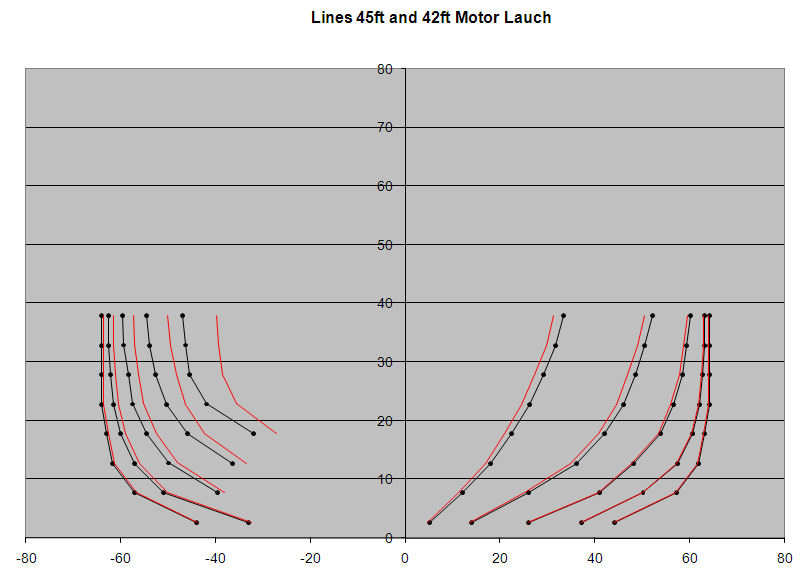
Plotting the measurements is a quick way to see if there are any measurement errors. I plotted both the stations and the waterlines and both must look right. (click images to open if they look poor in the post). Once you have the measurements right, you can start cutting the ingredients for the hull.
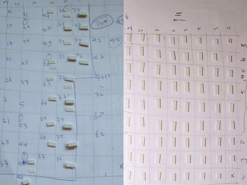
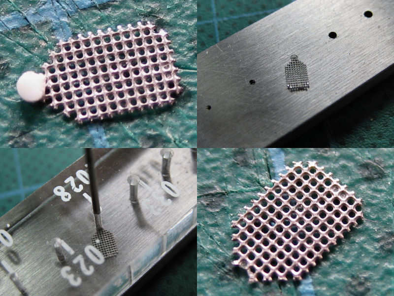
There are two basic hull forms for HMS Hood; the soft and hard chine types. The soft type hull requires many strips of different length, while the hard chine hull has fewer unique components. The left part of the image shows a collection of strips required for building a small hard-chine hull, the right part of the image shows all the strips laid out for easy construction of a soft-chine hull. In order to cut these strips accurately to size, please see the chopper page in the tips section.
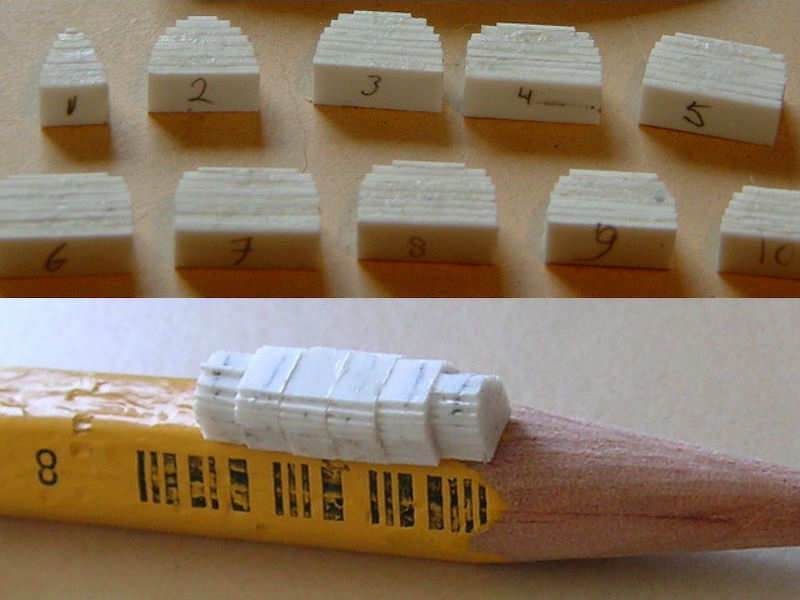
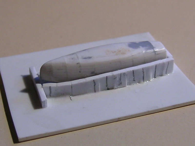
The tiny hull is now built up by stacking the styrene strips. I only glue two or three strips at a time, aligning them by eye and squeezing them a bit with the caliper. After all sections are glued and the glue has dried, the sections were sanded down a bit and glued to each other. The result is a very clunky hull that might look like it isn’t going to be anything. I completely covered the part with putty. When it has dried, just sand away until no putty can be seen. The small hull just barely contains the shape you want, so once the putty is gone you’re left with small hull. At the bow (and some sterns) you need to be careful not to sand away too much. Without too much trouble, you form the plastic blocks into a reasonably faired shaped.
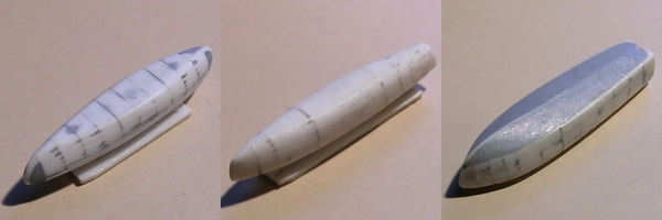
My first attempt is seen at left, with the bow reconstructed using putty. This isn’t necessary and the center image shows a hull make from styrene only. As both sections on either side of the maximum thickness are the same section width, I used strip twice as wide. The hard-chine boats were finished with putty. Note that very little putty remains on the hulls. Note that vacuum forming will damage the moulds a bit, so making a resin copy might be a good idea.
scaling hull lines
I could not find lines drawings of the 42ft motorized barge and the 16ft fast motor boat (skimming dish). I used lines drawings of similar hulls as a basis, with the 45ft barge as an template. For this barge I do have the top view, so I measured the top outline of this barge and used the 45 ft barge as a base template and scaled it accordingly.
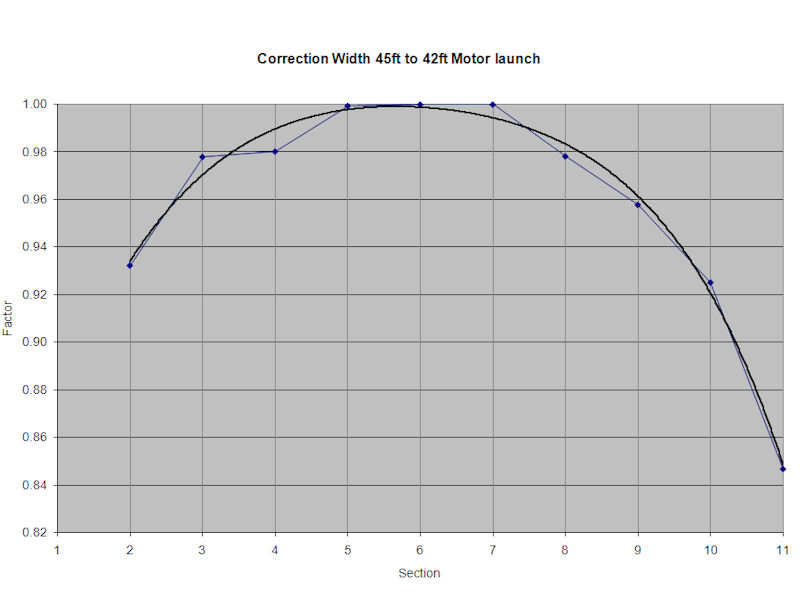
The above chart plots the normalized ratio of the beam of the 42ft barge to the 45ft barge (local beam divided by maximum beam). I then use a small averaging polynomial to obtain a smooth curve (e.g., a trend line in Excel). The height can be scaled linearly, by taking new thinner plates. This may require measuring all data again for the new plate thicknesses.
The results are compared and look fine.
After the hulls are complete and vacuum formed, the hulls need to be trimmed to size. For this, I use another cutting template. The height is taken from the side view of the hulls. Cutting it by hand doesn’t really work for me and when you need a few identical hulls, I really want something to look repeatable.
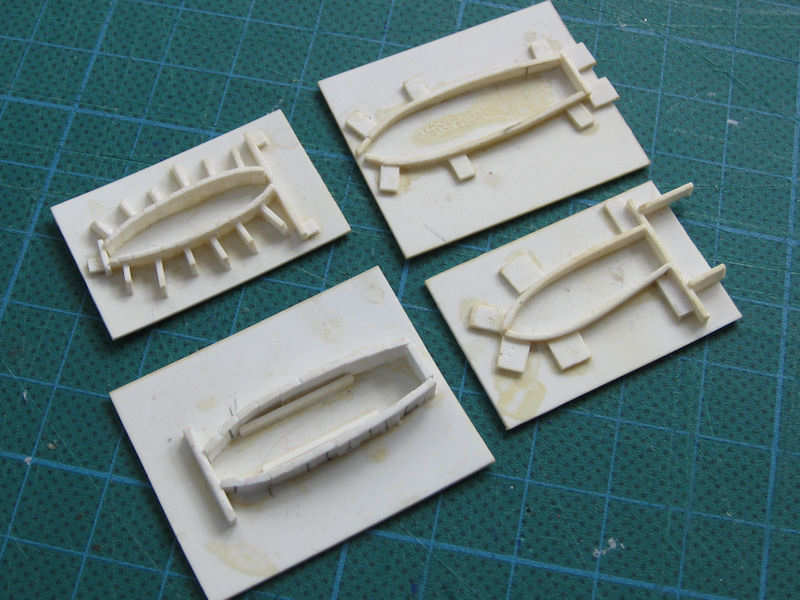
Here’s a pic I took today of a few of the cutting templates for the various hulls.
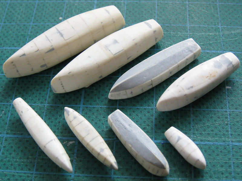
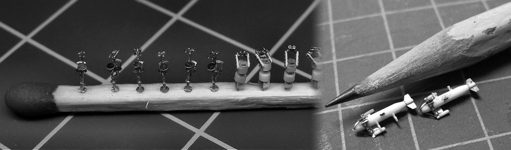
Another pic of all miniature hulls except the hard-chine 16ft fast motor boat which I apparently misplaced indefinitely. HMS Hood carried a 16ft dinghy and a 16t fast motor boat, for your information, and not two identical 16ft boats. The top row, from left to right, shows the 45ft motorized barge, the 42ft motorized barge, the 35ft fast motor boat, and the 32ft motor cutters. The lower row shows the 30ft sailing gig, the 27ft naval whaler, the 25ft fast motor boat, and the 16ft dinghy. Note how well the different lines of the various hulls have worked out. For making these small boats, it’s important that the outline at the deck is correct so that the cabins are not off scale. Note that he 45ft and 42ft models, based on the same parent hull form, look very similar.
I have an example spreadsheet right here to scale one set of data to the next. Here is the 25ft-fast-motor-boat sheet that adds the number of required strips. It also has a section where the sides of the hull are straight, so all values are interpolated linearly. This sheet also scales all measured values to the right model scale. None of the sheets take the thickness of the vacuum formed plastic into account, so perhaps you need to make everything a bit thinner if you really want to be properly scaled. For these hulls, I don’t think it’s really necessary.