Month: November 2008

Bridge Superstructure, part II

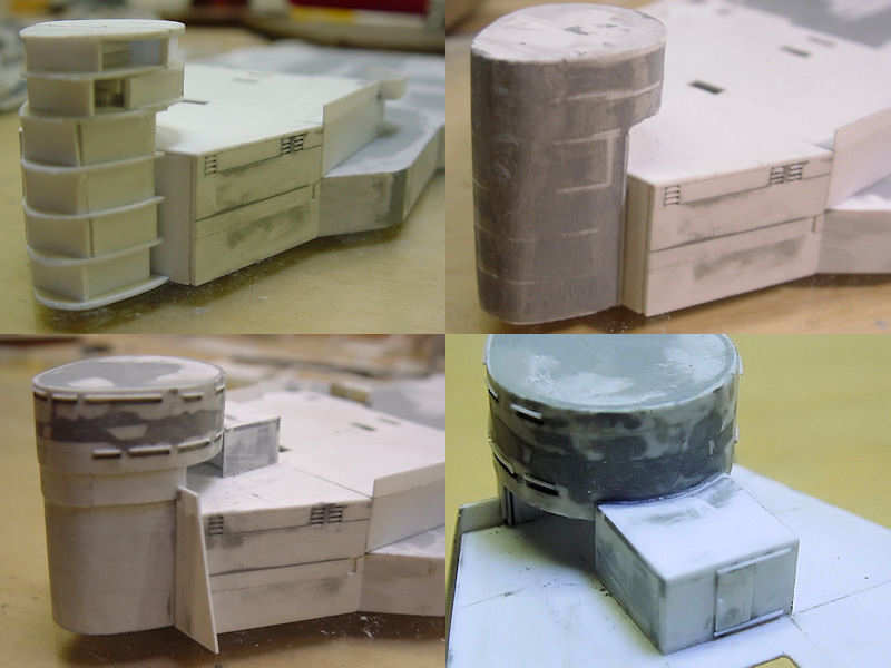
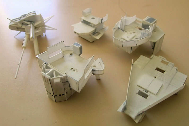
The bridge consists of five separate parts. From the lower deck up, they are: admiral’s signal platform, conning tower platform, admiral’s bridge, fore bridge and spotting top. These decks are placed on the conning tower deck of the previous post in this series. All these decks can be taken apart at any time, so that I can paint the decks and add the stairs and railing before gluing all decks together. It’s really difficult to replace a section, as they were cut simultaneously with all stair openings at the same position (filing all decks at once), so that was never a reason to keep the parts segmented at the time of building. The aft legs of the tripod are now also segmented, and drilling the correct locations was tricky. Once the bridge is completed, a rod can be placed through all parts of the tripod legs for a bit more stability of the parts. This picture is already quite old (2005 at the latest!). As mentioned earlier, this is already the second bridge. The first bridge was made using 0.25mm plate for the decks. This is nice and thin, but it warped a lot. Using 0.4mm seems like a small change but helped a lot.

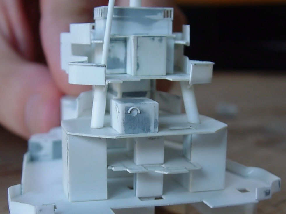
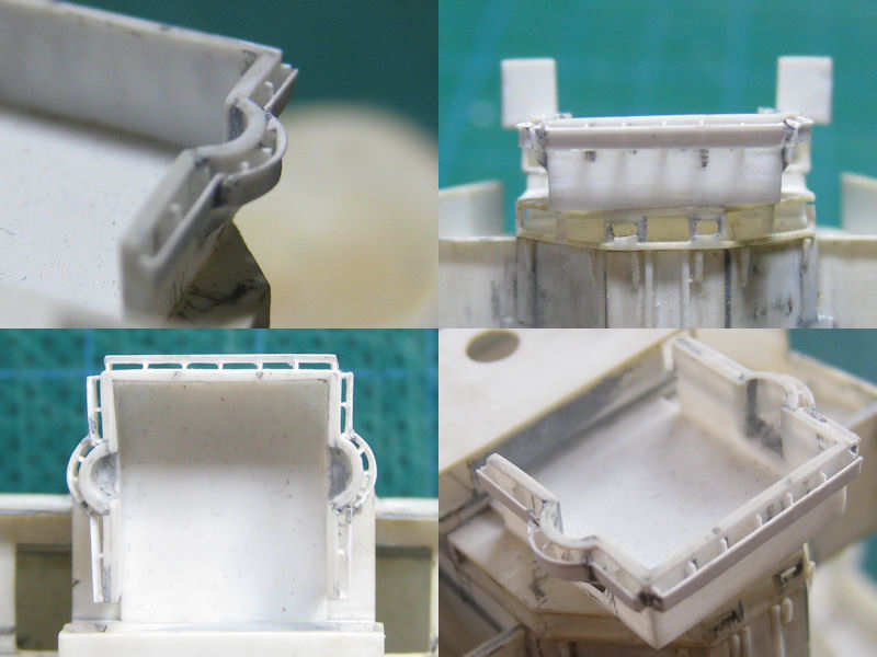
This is a nice shot of the aft of the bridge in progress. All the openings of all stairs cases are carefully placed. This is one of the details that take a lot of effort and—if all goes well, that is—won’t be noticeable when the model is done.

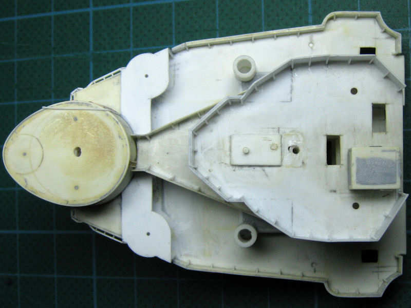
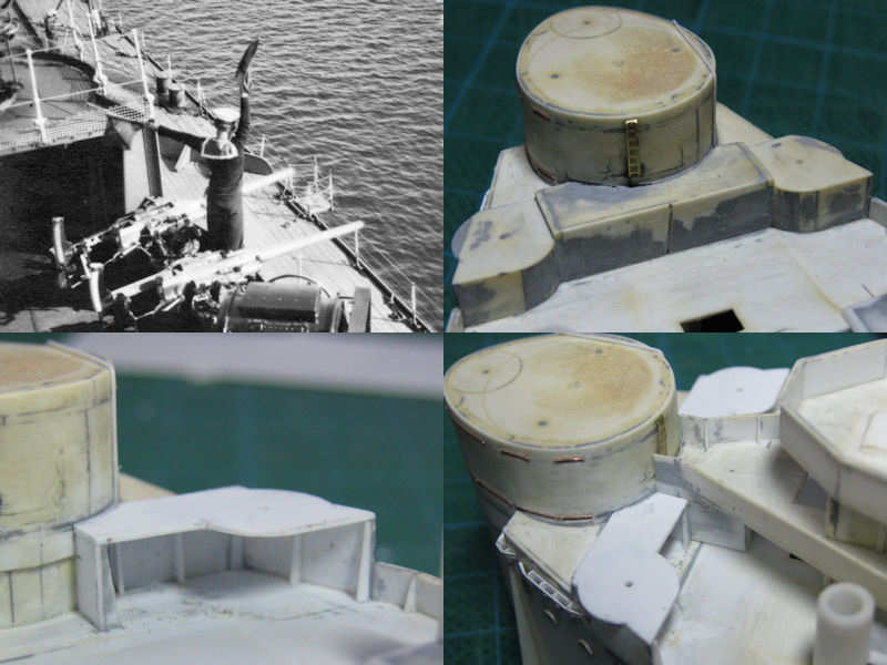
This is a picture of this weekend, showing the admiral’s deck from above. If you compare this deck with the available drawings, you’ll notice the layout is much different and there is a steel bulkhead around the deck. You’ll notice the scars at the forward left and right of the deck, where the old deck was rudely cut out and replaced with new parts (compare with the first picture). Chances are you have never seen this layout or bulkhead on any other model as this is a recent discovery based on a new picture.

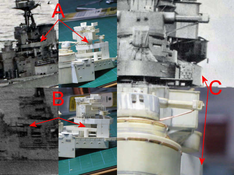
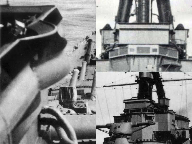
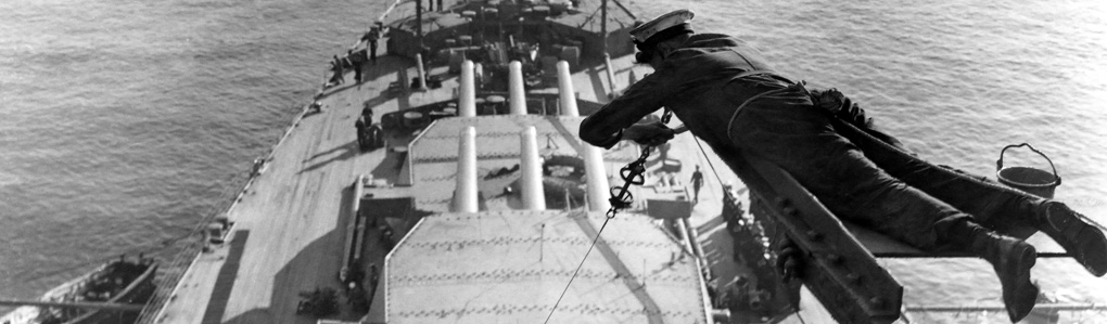
On this composite picture it is clearly visible that the new layout resembles the pictures quite well (from the HMS Hood site). At the top left image, the high splinter shield is seen wrapped around the bridge level. It steps down a bit with an inward step (A). The bottom image shows that this high splinter shield ends just above the 5.5″ control director base (B). The right image shows that the bulkhead is steel, not just covered railings, and that it can be seen that the shield makes a few angles; a small piece of the aft shield is seen at (C). This picture is not new, but I never noticed it.

Bridge Superstructure, part I

I’ve done a little work on the bridge, one of the major parts of the model. The entire superstructure from the deck up was built at least twice but I don’t have many pictures left of the original superstructure. As I’m working here and there on various parts of the superstructure, this category won’t be that organized.

These pictures were taken from the first bridge attempt and contained a lot of small errors. For instance, I choose a 0.25mm thick plate as a deck part which is too thin. A 0.35mm plate makes all the difference. The conning tower is built up from plastic plate and filled with putty. The detail of the slits in the armour plate of the conning tower was added by plastic strip. The side of the superstructure is made from strips, as to leave out a few spaces for a series of grids. This all didn’t work out very well and the entire model of the bridge was thrown out after some considerable deliberation. This is the major reason the model isn’t finished yet.

Here’s the mark II bridge base part. The conning tower is made from strips glued against a few support parts and the side of the bridge is a single plate. This works a lot better.

Here’s a nice recent shot of the conning tower and the rain guards above the view slits. This was very difficult to do, as I want to have the guards to droop down at the ends and still look properly. All the brass wires, made from 0.1mm winding wire, were first bent around a strip of the correct width, glued in place and trimmed. There’s some variation in height, but it’s more of a mess on the real ship!

A voice pipe can be seen curling over the roof on the conning tower into one of the viewports. After staring at my picture collection for an hour or so, I found a few images that show this voice pipe and added it. This is all the material I can find, but I think it is quite convincing. An eye for detail?

The platforms of the forward quad Vickers guns appeared to be open at the rear, and not closed as I originally thought. I spent this weekend carefully chipping away the old part and added a new platform. Much better!

A series of wind baffles are visible near the forward torpedo lookouts. Only a few photographs are available as this is a very late edition, but enough to make a good approximation.

The pictures of the air defense platform (the highest and open deck below the spotting top) was also fitted with a wind baffle and it again took a lot of time to find the right photographs to get an idea of the layout of this detail.

At left you can see that how it was fitted to the splinter shield, going around the small sponson. At right, the wind baffle is seen from two good angles.

Here you can see the model. The sponsons in the splintershield were particularly nasty to build, being both complex in shape and quite small! The front view shows the bridge suffered a bit from sanding, but the model itself looks good enough. The wind baffles were constructed from 0.13mm plate. A knuckle was added to the plates using a small folding jig.

Copyright © 2024 On The Slipway

Theme by Anders NorenUp ↑