
Not that many photographs are available of the weather deck amidships. This area was briefly out to the open but quickly covered by the shelter deck. Still, most drawings and the Anatomy of the Ship volume shows the location of vents and details to add.
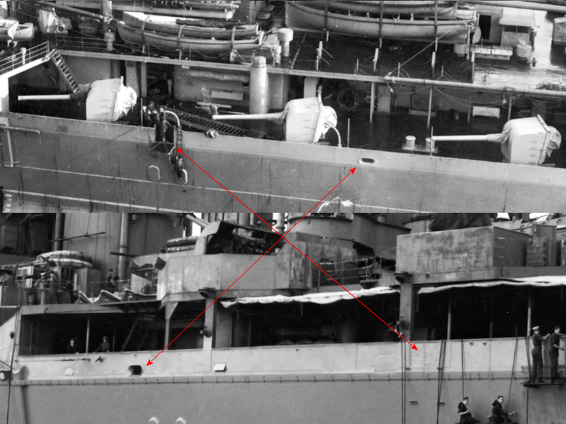
It’s just a minor issue, but note that the bulwark was changed when the boat deck was extended. The position of the accommodation ladder was moved aft when the pompom were placed in the 1929-1931 refit. Note that the ladder is stored on deck in the upper image. The fairlead apparently also switched position. Naturally, this means that the bollards placed on the deck were moved as well. If you go to the Willis collection of the website of the HMS Hood association you’ll notice the bollards just aft of the first of the three 5.5″ guns and the fairlead itself. This change is missed by all drawings so the exact position was estimated to be between the first and second 5.5″ gun.
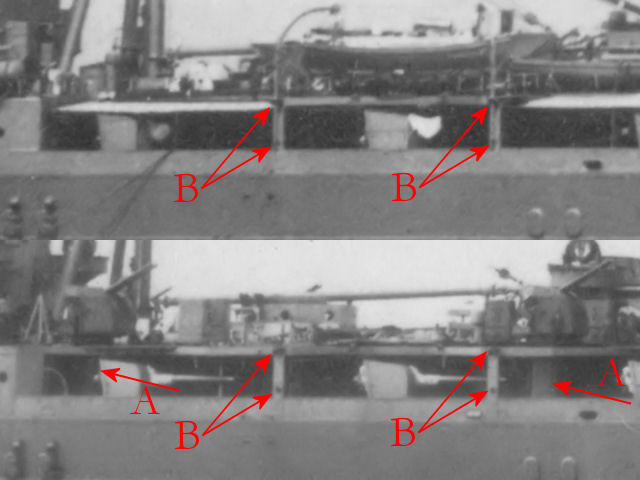
This image shows a few nice details. A 5.5″ ammo dredger hoist is seen at (A). All the 5.5″ ammo hoists weee removed by 1940, however, the 4″ ammo hoists on the shelter deck are all located exactly at the same location but one deck higher. As know the forward and after 5.5″ ammo magazines and shell rooms were converted to 4″ ammo magazines, I’m confident sure new ammo hoists were fitted even though these are not mentioned. At (B) a support stanchion is seen (with a white band) that are clearly indicated on the drawings. A ladder to the shelter deck is indicated at (C). There’s something at (D), but I haven’t been able to identify it. I’m not sure it was still present on HMS Hood in 1941 and decided not to add it.
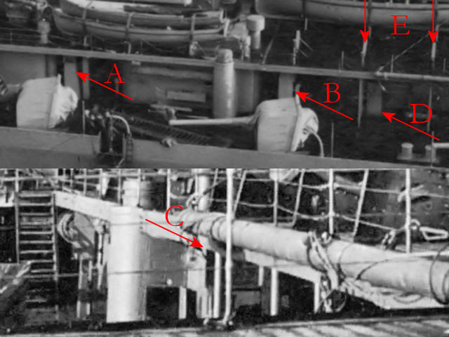
On this nice side view of HMS Hood two large deck vents are seen at (A) and (B). Note that the vent at (B) is seen to face aft at (C, from Warship Pictorial #20). A 5.5″ammo dredger hoist is visible at (D). Note that the cradles (E) for the boats and launches are exactly above the support stanchions.
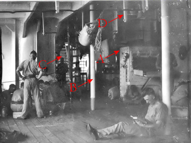
Pictures after HMS Hood’s various refits below decks are rare. Upon comparing pictures of HMS Hood from 1934 and 1939, it appears that support columns are placed below the 4″ guns at (A). The aft one is particularly vague. The R-class battleships do not have these columns below their 4″ gun mounts so perhaps I’m over-analyzing. Note the left-over detail from the davits at (B) that needs to be reproduced.
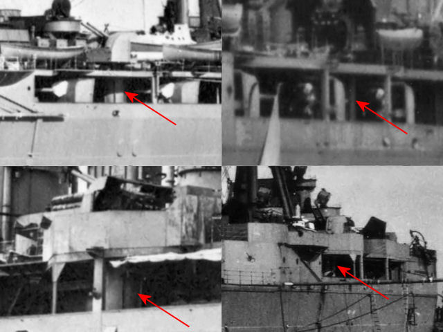
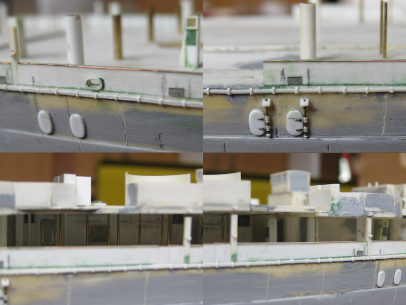
In these four small images support columns appear to be present, well enough to decide to add them to the model. If you have your drawings nearby: the in the bottom-left image is not the officers-of-quarters position (a small position at about the same location ), as this position was removed in 1929-1931.
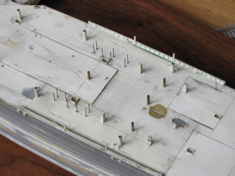
So, this is what the model looks like below the boat deck. One of the disadvantages of my model is that the hull is still the old White Ensign Model core. Because I “like” the way the hull looks now and the amount of time invested in it, I decided not to scrap that part. Still, the new styrene decks were added rather amateurishly; glued directly on resin and putty (oh no). Note the patchwork of replacement decks. This looks awful but will be very hard to spot once to model is done. One of the greatest risks is that the bond between the deck and hull will give way and the model is ruined beyond my emotional capacity for recovery. In order to avoid that, the superstructure pieces will not be glued to the deck; note the brass pins; the are drilled into the hull 1 cm deep acting as an anchor to the deck parts. Each brass pin has been tapped with a M1 thread (very carefully!) so that the superstructure parts can be screwed down, all cleverly hidden beneath gun mounts and directors. Some of the brass pins that remain visible on the model have been fitted with a styrene jacket for easy painting. The thinner support columns were drilled in using the drill press. The deck openings for the stairs going to the lower levels are visible.
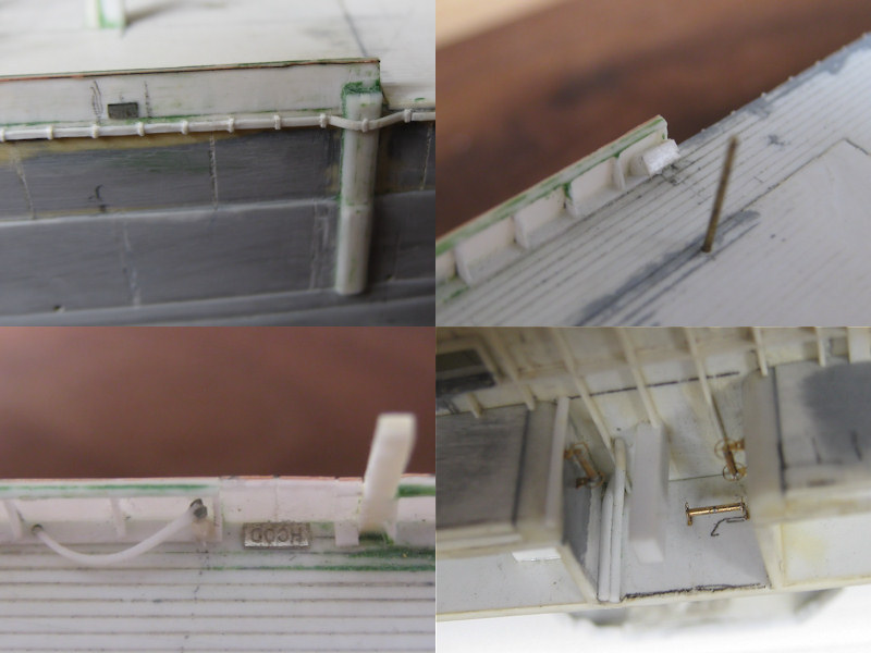
Details that are know to be present below decks are the afore-mentioned vents, hatches, wash deck lockers, 4″ ammo lifts, bollards, support pillars, davits and the chutes. The hatch was based on images of a King George V class battleship where the chute is in the open near the aft breakwater. The davits were made in series, four of which are to be placed on the quarterdeck. The four davits I liked least were placed below decks. A slight waste of effort, but nice for this very picture and people taking the time to check if all detail is accounted for. Note that the name place with the text ‘HMS HOOD’ is placed behind the hatches in the bulwark her name can now be found on six places on the model. The bottom-right image shows the cordage reels, the 4″ ammo supply hoist (that is, a bit of styrene strip) and rods leading to the mushroom vents (if you have a vent of deck, the piping has to go somewhere).
Now that most of the hull is complete I decided to add some additional detail: a small line scribed between contiguous armor plates. The artwork by Burt in his battleships books shows these lines and even though they are not very visible on most photographs I decided to add them anyway because it looks rather nice. Now, the lines by Burt prove totally imaginary after cross-referencing them with HMS Hood’s shell extension plan from the National Maritime Museum. It’s just a matter of counting the frame numbers, taking the non-constant frame spacing into account, and a bit of scratching to do. Here the hull problems resurfaced again and many lines required repair and rescratching, including some repair work of the armor belt (plastic) delaminating from the resin hull. Sigh, that was very depressing and it still looks bad. Perhaps I should just paint the model and be done with it. The hatches on the side of the hull were added as were the remains of the davits. These hatches were done twice, because I damaged the hinge system beyond repair during the line scratching.