Category: Superstructure

Funnels, Part II

Continuing from part I

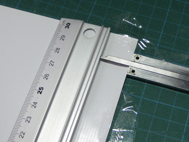
With the soldering going so well I decided to solder on a bit more and had some parts redesigned and etched.

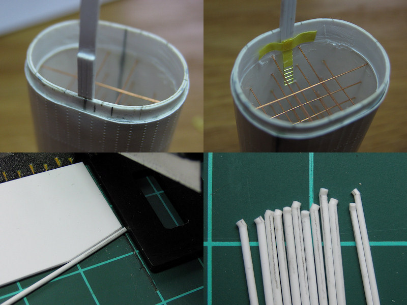
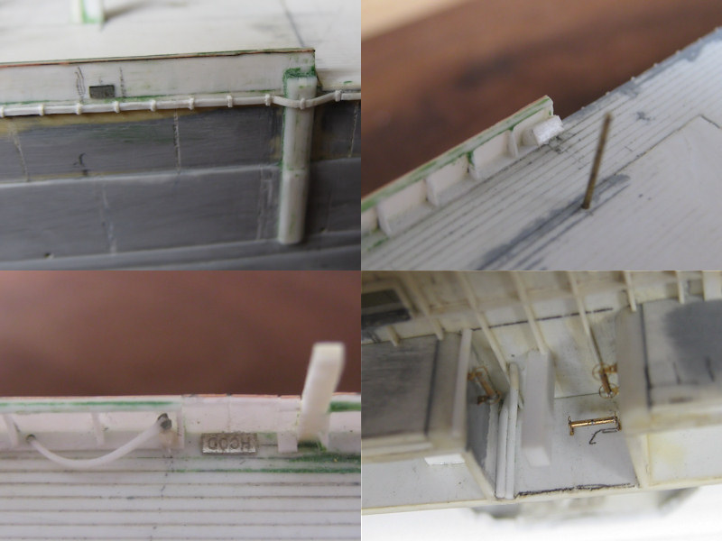
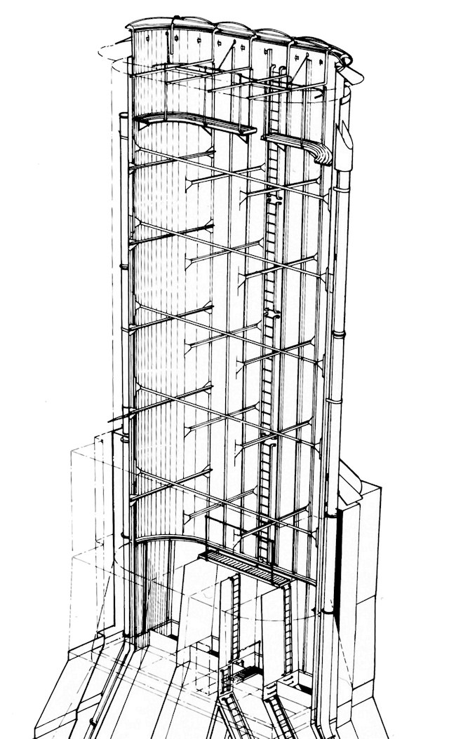
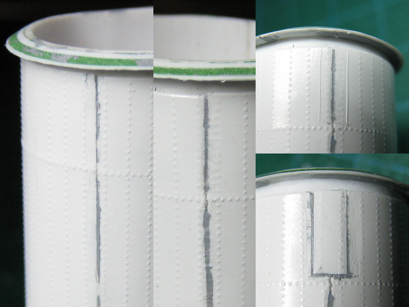
Some minor detail was added first. The two ladders on the inside of the funnel are placed with a jig so that the gantry will link up to it nicely. The ladder is by Aber, one of the few commercial products I have used (I’ll probably use my own ladders in the future). The steam pipes cluttered around the funnel are made from rod; drilled in, chopped up to give it that knuckle on the end, and fixed with brass wire. That is, I didn’t glue the pipes to the wire yet to avoid handling damage in that area.

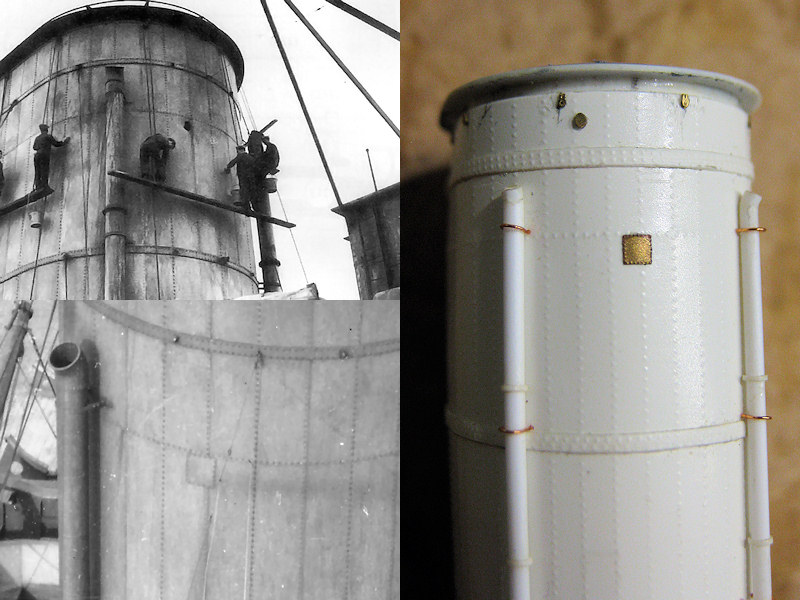
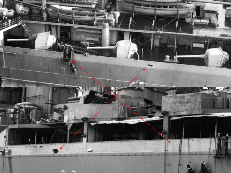
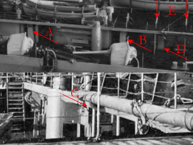
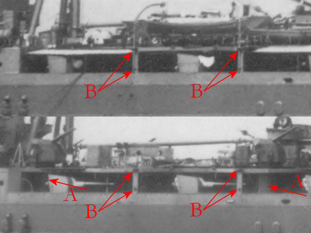
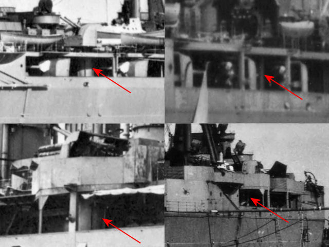
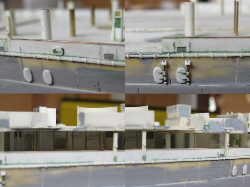
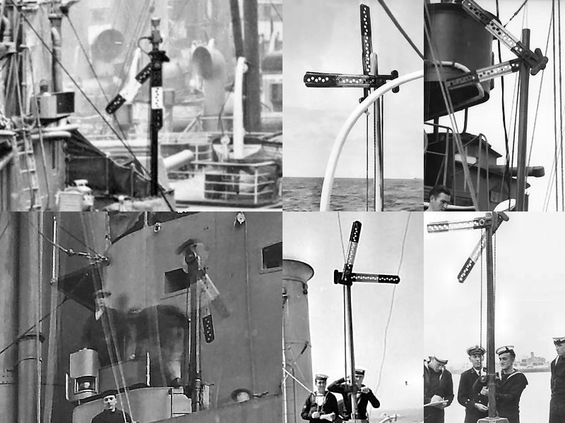
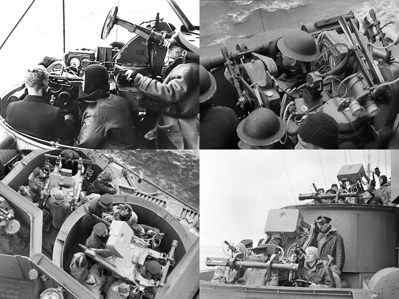
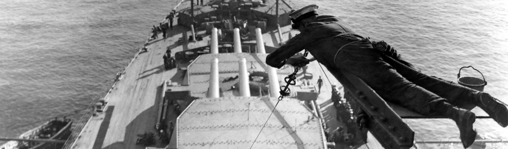
Note that there is a bit of damage on the aft funnel that was later patched up; a nice piece of detail to add. The top left image also shows the typical Royal Navy approach to painting the ship; they do not use the foot rails found on axis battleships with a series of pulleys and planks to stand on. It doesn’t seem very safe but it does save you building an awful lot of these foot rails. The pulleys are etched parts, folded once.

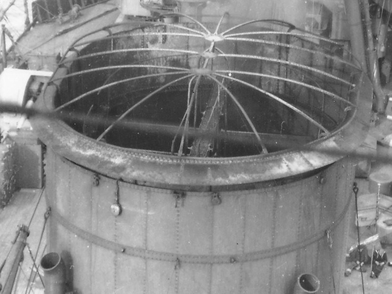
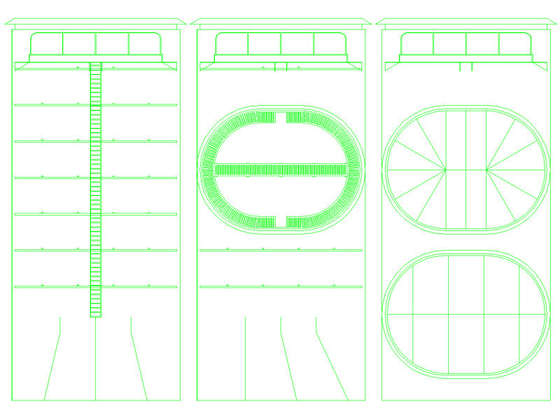
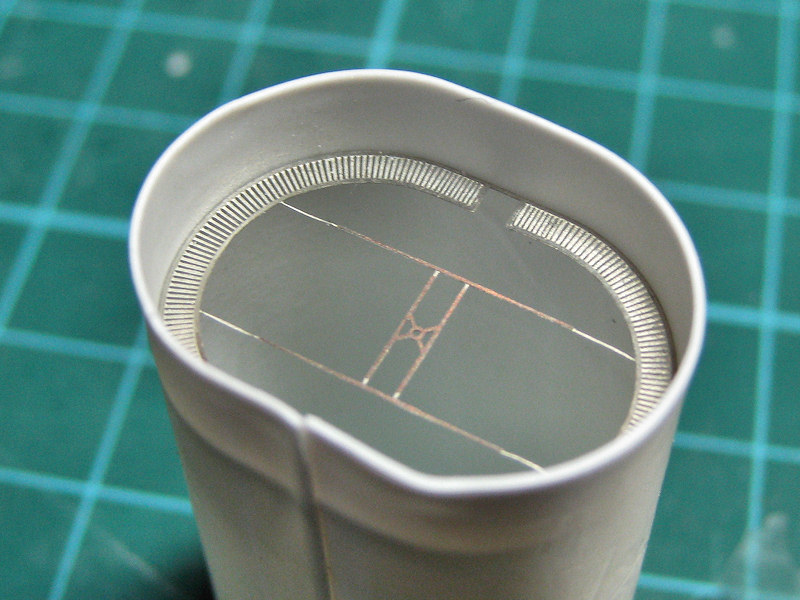
Here’s a sketch of the funnel cage.  The crew could access the funnel from below, climb to the top and fix an awning to the cage (but usually did so only when the boilers were out). I made this small drawing in Autocad of the funnel cage with a series of 0.2mm holes for the supports of the cage and for a few pins to hold the cage in place. A ring goes around the funnel cap supporting a series of arches. One large grande arche is on the ship center line. I decided to make a drilling template for the supports and support pins.

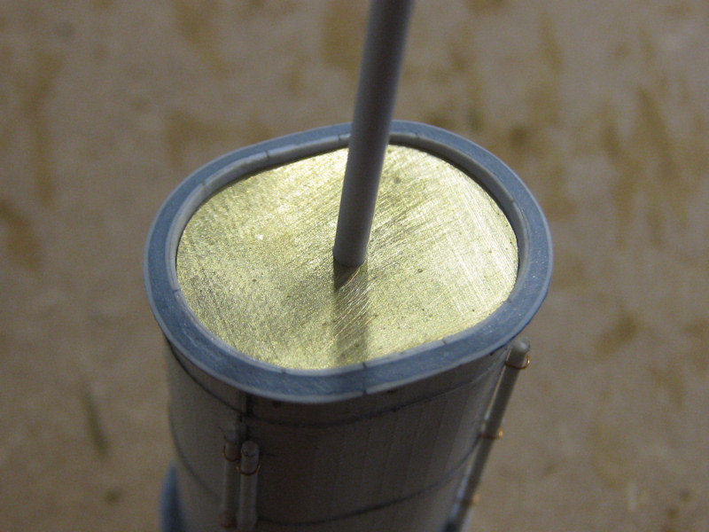
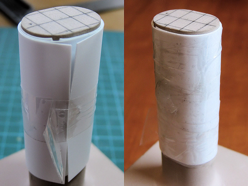
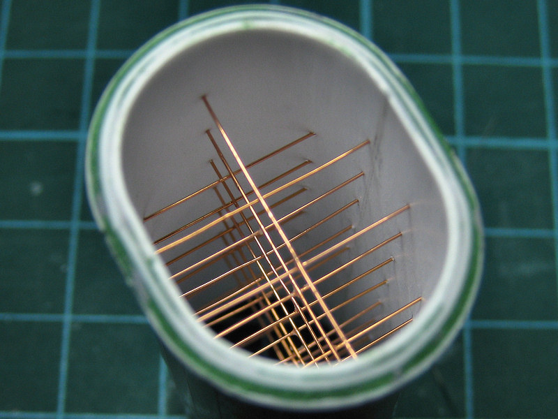
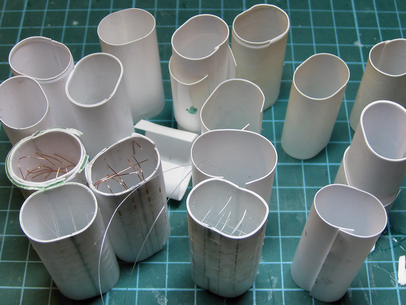
The inside of the funnel isn’t as perfect as I’d hoped and deformed a bit with all these layers of plastic going around it. Perhaps all these brass wires in the inside are a bit too taut. I already botched up fitting several well-executed gantries so I came up with a disposable fitting template to check the goodness of fit; should have come up with that earlier!

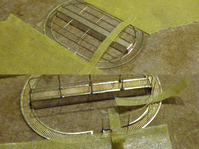
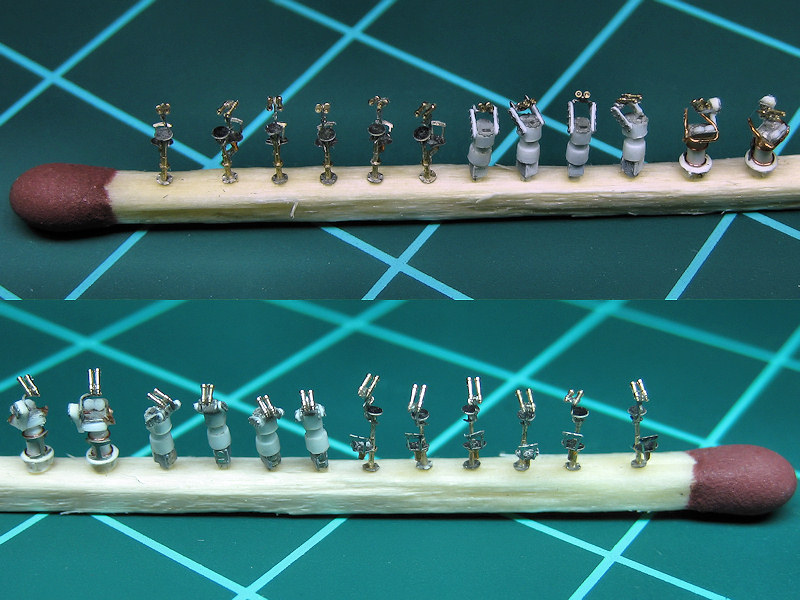
The soldering of the gantry itself was slightly tricky and I had to tape the parts down at every step. I added the solder like I’d normally add CA; a few spots to fix the part, with a line of solder when it’s more or less in place.

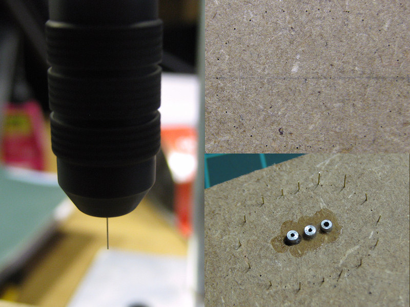
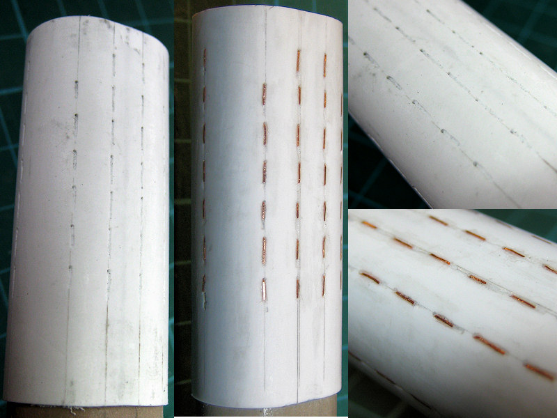
Now the template for the cage. I bought a pin chuck to hold the 0.2mm drills. When I put the pin chuck in the Proxxon chuck (Röhm actually) and dutifully fixed the chuck with the key at all three positions as my tool shop ordered me to do, the pin chuck was not centered correctly; I really had to try, try and try again until it was finally worked. I even bought a new chuck so that I now have a nicely centered chuck/pin chuck combination never to be separated. I made a picture of the spinning drill as proof it finally worked. I started with the drill protruding only a few mms from the chuck but the drill will usually walk away slightly—drilling off center—and the drill will break when the chuck is near the work piece; I lost three drills before I figured this out. So, I finally had the drill sticking about 1 cm or so from the chuck so that it could flex. The result is shown at right after drilling and with the positioning pins. The tubes at the center are supports for the arcs of the cage, made from aluminum so that the brass wire won’t be soldered to them.

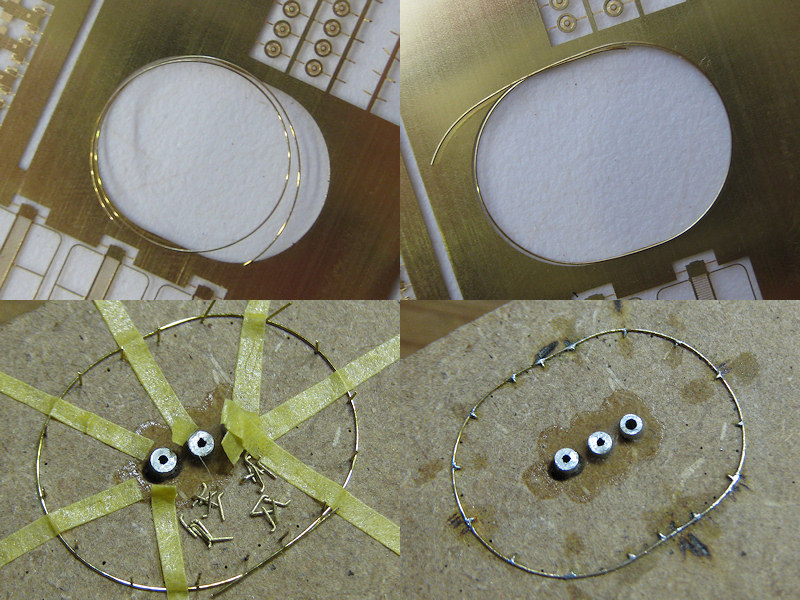
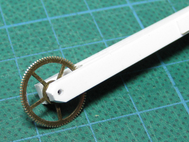
I had some room to spare on my last etch so I added a folding template for the ring of the cage; the brass was far too stiff to use this template but it did work to check the shape. I started by rolling the handle of my X-acto knife over a 0.2mm brass wire until the diameter was correct. With some pressure from a pair of pliers I added the parallel center until the shape was more or less right. The wire was transferred to the jig, held in place by tape and the supports were added one by one. I started opposite where the ends of the ring meet and cut the ring to size only when nearly all supports were in place. The positioning pins could then be removed.

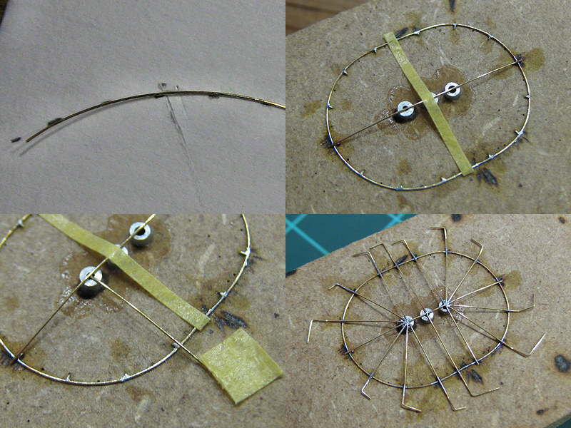
The arcs were bent into shape and checked against a high-tech drawing. The grande arche was added first, followed by the other arches. Note that the ends of each arc have a 90-degree bend; this allowed me to temporarily tape the arc to the jig and keep the direction of the arc upwards; otherwise it will just fall over all the time. I fixed the end of a single arch to the grande arch, fix the arch to the ring, and reapply to both ends in succession. By doing this, there is no stress in the solder and when I apply heat to the center they do not change position (much).

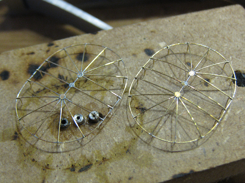
Afterwards three etched parts were added on top of the intersections of all the arcs. The difficulty was not so much avoiding the desoldering of all arcs but aligning the etchings themselves. The cage could then be lifted from the jig. One cage was damaged beyond repair at this phase. One cage took between five and six hours to make; this time was mainly spent looking through the Optivisor and handling the parts with tweezers and the soldering iron until the alignment was to my satisfaction (which is never, naturally).

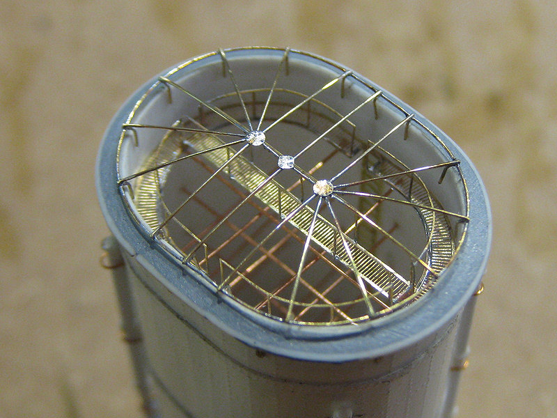
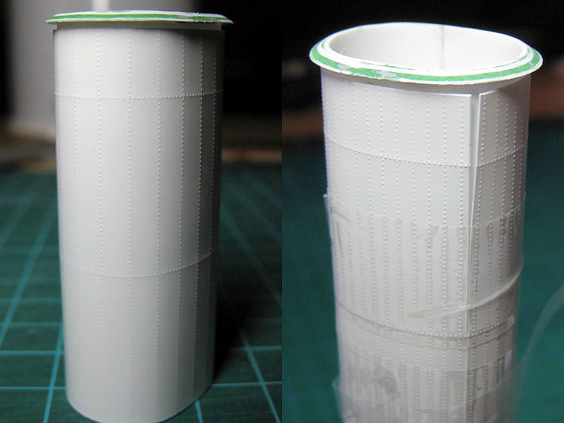
These funnels took more than a fair amount of planning and experimentation but now have a level of detail that I would not have thought possible a few years ago (cage and gantry are not fixed yet in this picture). The soldering allows for much better and clearer work than using super glue and it is much easier to correct.

Below decks

Not that many photographs are available of the weather deck amidships. This area was briefly out to the open but quickly covered by the shelter deck. Still, most drawings and the Anatomy of the Ship volume shows the location of vents and details to add.

It’s just a minor issue, but note that the bulwark was changed when the boat deck was extended. The position of the accommodation ladder was moved aft when the pompom were placed in the 1929-1931 refit. Note that the ladder is stored on deck in the upper image.  The fairlead apparently also switched position. Naturally, this means that the bollards placed on the deck were moved as well.  If you go to the Willis collection of the website of the HMS Hood association you’ll notice the bollards just aft of the first of the three 5.5″ guns and the fairlead itself. This change is missed by all drawings so the exact position was estimated to be between the first and second 5.5″ gun.

This image shows a few nice details. A 5.5″ ammo dredger hoist is seen at (A). All the 5.5″ ammo hoists weee removed by 1940, however, the 4″ ammo hoists on the shelter deck are all located exactly at the same location but one deck higher. As know the forward and after 5.5″ ammo magazines and shell rooms were converted to 4″ ammo magazines, I’m confident sure new ammo hoists were fitted even though these are not mentioned. At (B) a support stanchion is seen (with a white band) that are clearly indicated on the drawings. A ladder to the shelter deck is indicated at (C). There’s something at (D), but I haven’t been able to identify it. I’m not sure it was still present on HMS Hood in 1941 and decided not to add it.

On this nice side view of HMS Hood two large deck vents are seen at (A) and (B). Note that the vent at (B) is seen to face aft at  (C, from Warship Pictorial #20). A 5.5″ammo dredger hoist is visible at (D). Note that the cradles (E)  for the boats and launches are exactly above the support stanchions.

Pictures after HMS Hood’s various refits below decks are rare. Upon comparing pictures of HMS Hood from 1934 and 1939, it appears that support columns are placed below the 4″ guns at (A). The aft one is particularly vague. The R-class battleships do not have these columns below their 4″ gun mounts so perhaps I’m over-analyzing. Note the left-over detail from the davits at (B) that needs to be reproduced.

In these four small images support columns appear to be present, well enough to decide to add them to the model. If you have your drawings nearby: the in the bottom-left image is not the officers-of-quarters position (a small position at about the same location ), as this position was removed in 1929-1931.

So, this is what the model looks like below the boat deck.  One of the disadvantages of my model is that the hull is still the old White Ensign Model core. Because I “like” the way the hull looks now and the amount of time invested in it, I decided not to scrap that part. Still, the new styrene decks were added rather amateurishly; glued directly on resin and putty (oh no). Note the patchwork of replacement decks. This looks awful but will be very hard to spot once to model is done. One of the greatest risks is that the bond between the deck and hull will give way and the model is ruined beyond my emotional capacity for recovery. In order to avoid that, the superstructure pieces will not be glued to the deck; note the brass pins; the are drilled into the hull 1 cm deep acting as an anchor to the deck parts. Each brass pin has been tapped with a M1 thread (very carefully!) so that the superstructure parts can be screwed down, all cleverly hidden beneath gun mounts and directors.  Some of the brass pins that remain visible on the model have been fitted with a styrene jacket for easy painting. The thinner support columns were drilled in using the drill press. The deck openings for the stairs going to the lower levels are visible.

Details that are know to be present below decks are the afore-mentioned vents, hatches, wash deck lockers, 4″ ammo lifts, bollards, support pillars, davits and the chutes. The hatch was based on images of a King George V class battleship where the chute is in the open near the aft breakwater. The davits were made in series, four of which are to be placed on the quarterdeck. The four davits I liked least were placed below decks. A slight waste of effort, but nice for this very picture and people taking the time to check if all detail is accounted for. Note that the name place with the text ‘HMS HOOD’ is placed behind the hatches in the bulwark her name can now be found on six places on the model. The bottom-right image shows the cordage reels, the 4″ ammo supply hoist (that is, a bit of styrene strip) and rods leading to the mushroom vents (if you have a vent of deck, the piping has to go somewhere).

Now that most of the hull is complete I decided to add some additional detail: a small line scribed between contiguous armor plates. The artwork by Burt in his battleships books shows these lines and even though they are not very visible on most photographs I decided to add them anyway because it looks rather nice. Now, the lines by Burt prove totally imaginary after cross-referencing them with HMS Hood’s shell extension plan from the National Maritime Museum. It’s just a matter of counting the frame numbers, taking the non-constant frame spacing into account, and a bit of scratching to do. Here the hull problems resurfaced again and many lines required repair and rescratching, including some repair work of the armor belt (plastic) delaminating from the resin hull. Sigh, that was very depressing and it still looks bad. Perhaps I should just paint the model and be done with it. The hatches on the side of the hull were added as were the remains of the davits. These hatches were done twice, because I damaged the hinge system beyond repair during the line scratching.


Bridge Equipment, Part II

Updated may 2012: added information on the CF25 binoculars and acknowledgement & permission to use Frank Lagorio’s images of the binoculars.

Continuing from Part I , where I pointed out what goes where, here I have some images of the individual stands.

I collected nice images of all the bridge equipment components, trying to figure out what was what. I flipped through well over 15,000 images in online archives, probably missing a few here and there. I even bought a second-hand book because it contained a single good image of the air-defense officer’s sight. I put the best images in a CAD program and estimated the dimensions for each sight. Crew should be able to stand behind the sights at eye level, they should not be higher than the bulkheads they’re behind, and they should scale properly with each other, and so forth. I know that one Air-Lookout Sight is fitted to HMCS Haida, but that’s a bit out of the way for an actual measurement. Still, I ended up with some probable and consistent dimensions, or so I believe. At least most of these sights have one thing in common: the binoculars. Not the most accurate frame of reference, but still.

The binoculars are Barr & Stroud CF41 Admiralty Patterm 1900 night binoculars fitted with with built-in filters (yellow, green and polarizing). According to the Dock Museum, it measures LxBxH=235x170x90 mm, or about 0.67mm long at 1/350 scale, close enough to the 0.69-0.70mm I estimated from photographs (3-4% off). The bottom left binocular is actually the CF25 Admiralty Patterm  1949  with a 7×42 magnification type used primarily by observers of  the Fleet Air Arm, not the larger CF41 with a 7×50 magnification. The objectives are fitted with telescopic sun shades/spray shields, explaining the most obvious visual differences as seen bottom left. There’s quite a few people collecting them and a few of the better images of bridge equipment were found on binocular fora (none that mattered for HMS Hood, unfortunately). These images were using with permission from Frank Lagorio’s Flickr Account. You can pick up a pair on ebay from as little as 30 pounds; quite cheap as apparently many of these units suffer from prism separation. Note the yellow Admiralty arrows, designating acceptance into the navy. So, if you manage to build 1/350 bridge equipment and then manage to get 1/350 binoculars: they should have a pair of yellow dots.

This is the air-defense officer’s sight; quite bulky. . A chair is fitted to the pedestal of this director than apparently can be swung out of the way. It appears that the voice pipes can be mirrored for post side and starboard units (compare the left and bottom right image).

I used these images to make a simple CAD drawing. The chair can be seen at right at a near-ninety degree angle with the top of the unit. The center-bottom image is taken aboard HMS Hood (mirrored).

Here is the Air-Lookout Sight (Called Sky Lookout by the USN). It’s pretty well covered, that is,  now that I know what it looks like. The top is black with some lettering. Notice the aircraft recognition chart in the top left image of HMS Suffolk and the sunblocks in the lower-center part of the image. I noticed a sailor on the image of HMS Hood’s air-defense platform carrying this (one image up) and it appears to be standard issue for the lookouts.

Here’s the model interpretation, consisting of a few etched and CNC-lathed parts.

Now, in my previous post I mentioned a director for the UP launchers. However, in the Admiralty Fleet Order C.A.F.O. 2163.— 7-in., U.P. Mark I Equipments. Removal from Ships when replaced by Oerlikons (G/T.S.D./864/41 6-11/1941), a transcript of which is present on the official HMS Hood site clearly states that Air Look out sights pattern 12951 should be demanded from the nearest Naval Store Depot for each U.P. sight surrendered when these sights have been used in lieu of Air Look out Sights. So, are ALOs normally used as UP launcher sights?I do not see any unknown sight on HMS Prince of Wales’ bridge when fitted with the UP launchers, so I assume so.

Here’s the searchlight sight, with only one proper image scanned from Raven & Roberts British Battlecruisers of WWII book. This unit is clearly modeled by John Haynes; paying more attention to his work might have been a time saver.

and the CAD drawing including etched parts. I didn’t bother to add all etched parts, being nigh invisible when placed on the bridge.

A Perolus is fitted to the center of HMS Hood’s air-defense platform. The model hasn’t been completed yet. Note the sight at the bottom left image, far left.

Here are the models for the ADOs, ALOs and SLSs. Don’t worry, this is a large match. I had a few parts lathed by MASTER; I wanted to have the binoculars to be hollow and just couldn’t do it using my own lathe. As I needed 30+ parts, reproducibility became an issue. This is quite problematic when you have trouble with just one decent part. MASTER could actually get all (yes, all) the detail into these small parts and did an excellent job. They also milled the pedestals and the Vickers Valchorns (not shown). The parts were tricky to make, naturally, but the binoculars where quite easy; note I added the binoculars with and without the sun shades randomly. The chairs for the ALOs were first glued to a brass wire, then to an etched part and then to the pedestal. Clearly a part too many! It’s easy to get lost with the design of etched parts when they fill a 24″ monitor. I lost nearly no binoculars or chairs, but a lot of chair supports. The chairs for the ADO have yet to be added. No wire in the design here, fortunately.

A semaphore is not bridge equipment in the sense it’s a director or range finder, but is typically placed near the bridge with the other signalling equipment (lights, flag lockers). There was some discussion on a forum what the colors of the arms were (perhaps yellow/orange, as for the semaphore flags), but the website Royal Signals mentions that most signal arms were either white or black, or a mixture of both. […] On the ship there were often two types, the Mast head version with arms nine feet to twelve feet length, and the “bridge” mounted version […] with arms of six to eight feet length. I have my etched part at 5ft and they appear over-scale to me. Anyway, note the pattern in both colors and in the holes of the semaphore arms. These will be constructed when my model is being painted. The images are from random vessels with HMS Hood bottom left.

Next to the equipment known to be aboard HMS Hood, I have a few other close-ups I collected. These appear to be captains sights, indicative by captains near them (I think this makes sense).

There is supposed to be a target bearing indicator on the upper bridge wings of HMS Hood just below the air-defense platform and I assume it’s some sight; not another ADO. The left one certainly wouldn’t do , but I have no idea what type it could be. The right one would do; not visible in a photograph without the binoculars fitted.

Another nice set of sight variations, shown quite clearly. This is the Pelorus Sight.

This last one is the universal sight, a sketch of which can be found at the Historic Naval Ships Association. This unit was (amongst others) fitted to HMS Vanguard.


The Pompom director Mk I was described here. Not much was found for the Mk II and Mk III, but I have some images of the Mk IV to throw in so why not. The Mk IV was introduced in 1940 and can be seen aboard HMS Prince of Wales and HMS Kings George V (shown at right; note the absence of the radar aerials top right). Only the top-left image shows a Mk II/III. I have found not other photographs of the PPD Mk II/III. Fortunately I have the drawing from John Lambert Plans showing the unit in detail. A replacement of the model I have will be built later, with more etched parts and additional detail.


The three images shown above are all Mk IV pom-pom directors.  Note that these images show the director without the optical rangefinder which was removed in March 1944 from most units to reduce crew size.

One unit I mentioned in part I was the barrage director. I haven’t found a good image except one you can look up at the Australian War Memorial. The UK National Archives contain a pamphlet on the unit but the costs were a bit too high for this blog post.

Should you want to consult the Austrialian War Memorial (AWM) or Imperial War Museum (IWM), check out the following images:

AWM: 0356, 00313, 00627, 016988, 017502, 017637, 029536, 029538, 029562, 075411, 078120, 084640, 084641, 084642, 084644, 084645, 089369, 110179, 112191, 112341, 112355, 112360
IWM: 000872, 000874, 000876, 000878, 000888, 002873, 003651, 003883, 004218, 005667, 007696, 008432, 011001, 011213, 011803, 018039, 022617, 024208, 024326, 112355.

Funnels, part I

The models for HMS Hood’s funnels were already completed a few years ago and were of the few remaining parts of the first generation. The walkway at the center of the funnel was solid styrene, not a nice new etched walkway and the railings weren’t done so nice. So, I decided to have new parts for the funnel in the etch set for the walkway and the one-bar railing and start all over. Little did I know that these were the parts with the highest failure rate of any sub project I did so far.

This is the only one good shot (known to me) of the funnel interior, taking from high up in the bridge structure. It would have been wonderful if the sailor who took the image would have taken one of the funnel closer to the bridge so that the interior would be fully visible, because almost no other information is to be found. You have to interpret the image careful to distinguish between the railing of the walkway and the vertical and horizontal supporting bars and stays. The first thing to note is that there a walkway going around at the edge (so that the crew can deploy and fix a canvas cover) and a walkway in the ships length direction, but there is no walkway across the funnel in beam direction. Second, note that the (only) walkway across the funnel ends a bit higher at the far than the walkway around the funnel. As the funnel cage is curved, it would make sense for the across walkway to correct for this curvature and be a bit higher so the crew can pull the canvas cover over the grid. These covers are rarely used and are seen mainly when ships are being built or when mothballed

Few drawings of the funnel interiors exist at all but I managed to find two in Anatomy of the Ship (AOTS) Dreadnought and Belfast. This image is from the former source, by John Roberts. Even here it is mentioned that the exact layout is not known and is based on contemporary design. I decided to “create” HMS Hood’s funnels based on this information. You can notice a few things in this wonderful drawing. First, a ladder is seen from deep within the funnel going toward the walkway. The crew had to access the funnel from the upper deck. Now, if you look at the top image, you’ll notice that there’s an opening in the railing of the walkway. Hence, an opening for a ladder must be present for HMS Hood’s funnel as well. So, the shape of the walkway is distinctly different for the walkway as sketched by Roberts in AOTS HMS Hood.

Second, a large number of internal funnel stays are visible. The position of the stays remains unknown, except the two in the top image. Two vertical supports from the funnel cage down to the walkway seem to be at the same position. However, only two supports sound a bit low so I added two additional rows. I cheated a bit, as you cannot see them in the top image, so I decided to let those additional two stays start a row lower down. The stays end above the division plates at the bottom of the funnel. I didn’t add an etched walkway for this funnel interior, as I forgot about it and the previous version of the funnel ended one deck higher on the model so it couldn’t be placed. So, I’ve hacked that part away to show the division plates. Anyway, the design for the educated-guess funnel interior is now done.

A hollow funnel is one thing, but snugly fitting the etched part is something else, so I experimented a bit. I had a mould made from the dimensions of the etched walkway and wrapped it with plastic plate and put it in the oven. I spent a lot of time playing around with the plate thickness, the dimensions to get a good part, the temperature and the heating time. I ended up at 150 degrees (C) for two and a half minutes. The result is a thin 0.25mm plate with the correct shape. A second plate was wrapped around the first one and they were glued together. I had to add a few markers so that the plates were glued in the same position when they were heated, of they might deform the funnel a bit.

The result is a heat-treated funnel that fits the etched part like a glove! (the part in the middle is the antenna for the Type 273 radar and is not part of the funnel).

Adding the stays was the next experiment. I make a small ring from two additional layers of heat-treated plates and drilled in the funnel with a 0.2mm drill. Brass rod was inserted, glued with CA and later trimmed to size. I made several attempts, as a small misalignment of a row of holes showed up only too easily. The rod was added with the funnel on the mould to have something to hold the funnel with, lowering the mould with each successive row.

The result looks quite good, though I had to be careful not to exert too much force bending the brass rod which doesn’t bend back. Corrections can be made, but the results were not always too precise for my taste. So, for my second series (reason for doing so stated below), I tried using fishing wire. A series of channels was carved in the outer plate and the wire was weaved around the funnel. This did solve the problem of a brass wire not being able to stand tension, replaced by a wire that couldn’t take compression. So, I had to use some force pulling the wire taut, and I tore a hole through one of the funnels at the last pass (of course). Not so useful either. Still, all the channels and adding some pretension did work out quite well, so I went back to brass wire.

So I kept the idea for the channels and added some tension by pulling the wire and bending it downwards before trimming it to size. A third layer of styrene was added to bring the funnel to its required thickness before adding the exterior detail: next in line were the rivets on the outside of the funnel.

I already added some rivets to the tops of the main gun turret and decided to continue that technique here. I visited a repair shop for antique clocks and they gave me a collection of very fine gears. I made the tool you see in the picture above.

The plate width required for the funnel was first measured carefully using test plates and divided in strips. Using a table, the caliper, and a ruler, I rolled in line after line of rivet detail.

The result is a nice plate, a bit over-scale, but the effect should be worth it.

Adding the plate proved to be quite troublesome, as you cannot use normal glue as that will melt the thin plate and using superglue leaves very little room for error. Here can see the test fits of the plates (I had only half the rivets on the left funnel, so it was replaced).

The problem with the first set of funnels was that I accidentally removed a bit of rivet detail. The split between the plate ends is cleverly hidden behind steam pipes, but still, people may want to go searching for errors for the funnels just to see if there’s a plate line and spot the ugly area. I tried to repair this part by cutting out a part of the riveted sheet and add some replacement sheet, making matters much worse! These funnels were trashed, something I learned to regret later on, as these funnels were really a lot of work.

So here are the last versions of the funnels. I didn’t manage to have the horizontal bolt lines align properly for both funnels. Gluing was quite tricky, as the plate needs to be aligned properly and the smallest deviation will show up. Work to fast and you can make an error. Work to slow and the glue may form lumps that will show up immediately and you need to carve off the plating and clean the funnel (another hour or two). The split is filled and looks reasonably fine on a close-up and it’s tricky not to damage the lines of bolts on either side of the gap. Do note that the spacing between rivet lines along the split matches the distance between other lines quite well (hurray for planning ahead). Fortunately the double steam pipes, one set per funnel both over the split, will run over the horizontal lines.

Here you can see a collection of the failures.

Copyright © 2024 On The Slipway

Theme by Anders NorenUp ↑