
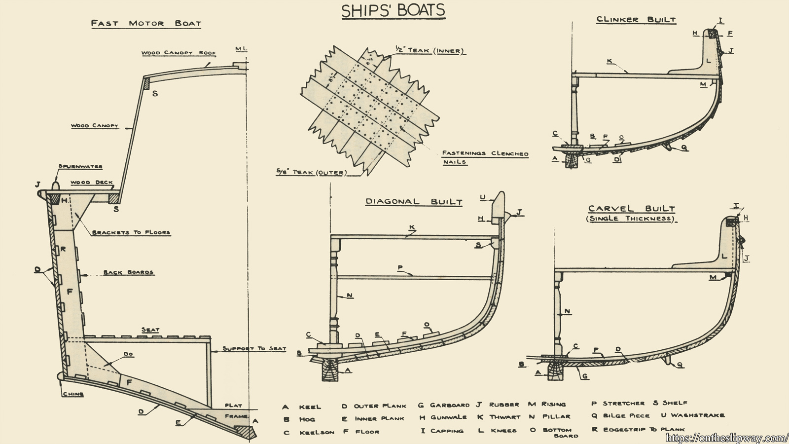
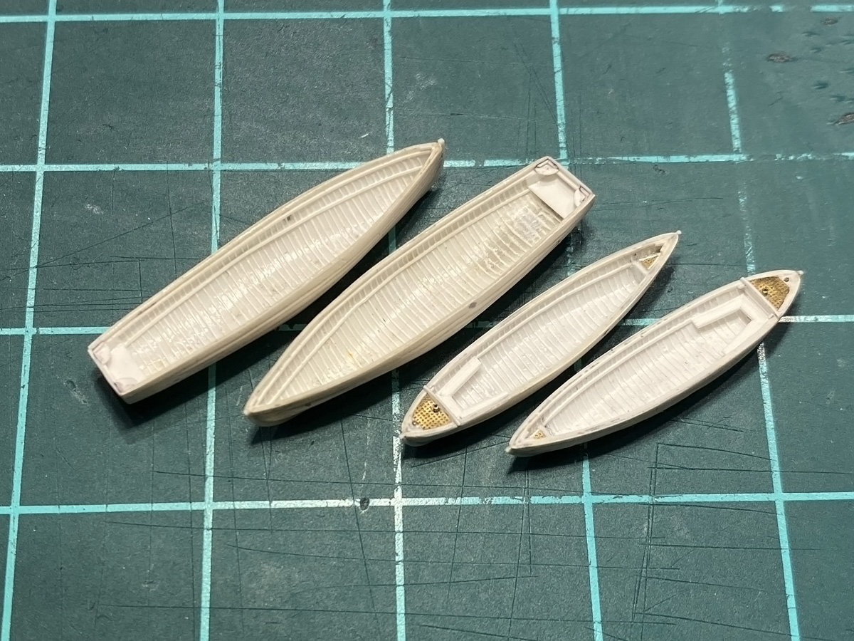
I started experimenting with the model of the gig, trying a few techniques to get all the details in working with even thinner styrene than I normal use (0.1 and 0.2mm by Wave, now sold out?). This image from Newton (1970) shows a few variations of how the hulls were built. Gigs are usually carvel-built, and the cutters and whalers are clinker-built (or lapstrake). Note that some fast motor boats have (partly) clinker-built hulls as well, e.g., the 16ft and 30 ft fast motor boats. I have not yet built up the courage to make a small hull from strips alone on this scale and decided to start with vacuum-forming for all.

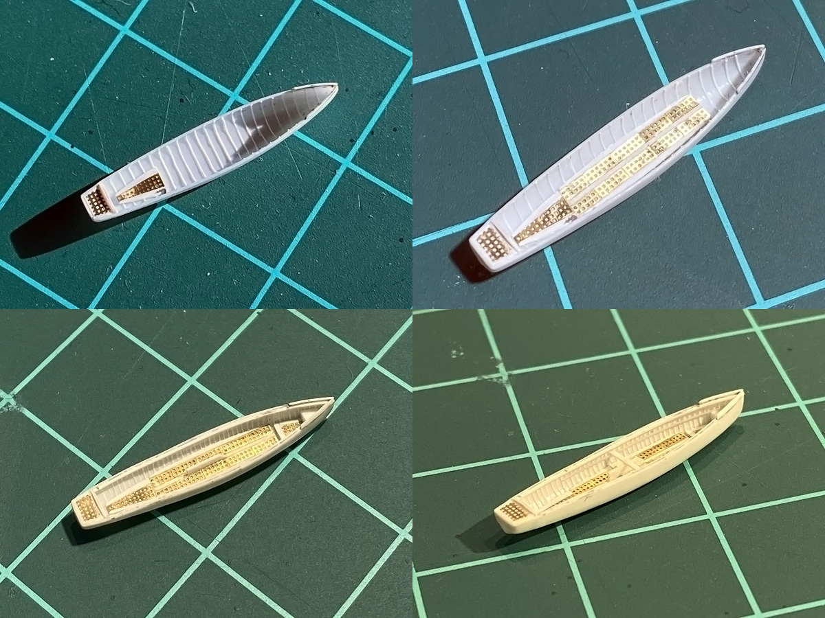
Top left shows a cutter, a gig and two whaler plugs. The recipe for the hull form plugs is the same as for the pinnace: simply use the chopper to cut strips, stack and sand the result until no steps remain visible.. The setup for my high-tech vacuum forming is quite basic; simply put the oven to 200 degrees, let the styrene melt a bit and done. That is, a few attempts are normally required before all the folds in the styrene are ‘just right’, but if it’s not right you can put the styrene back in the oven again. The hulls may have minor defects , near the transom or the cutter’s straight stem; some repair work was usually needed. The forefoot of the straight stem was filed off, replaced by a block of plastic filed back into shape. I made two whaler plugs because I was worried the plugs accumulate damage with each forming action (they do, but not enough to worry when you need only a handful). After the final forming I glued a few strips and spacers (-0.25mm margin) as a cutting outline; this gives a nice curvature along the hull without much difficulty and the process repeats well enough.
Would it be possible to add all the timbers—the small frames—to the inside of the hull? The problem is that an estimate of the spacing between the timbers is about half a millimetre, so that means a) many strips and b) the strips need to be very thin to look convincing. But, the thinner the plastic the higher the risk of melting them when gluing; I used Wave 0.1mm plate cut to square strips with the chopper. I started with the usual refinement tactic of adding strips at a wide spacing (4mm), filling in strips half-way in three sessions; much easier to eyeball them into the correct location. At first I stopped at a spacing of 1mm, but after the bottom grids where added I felt confident enough to add the rest too. I tried various Tamiya glues; the ultra-thin glue barely does anything as it evaporates too quickly and is largely useless for this type of work. The regular thin cement works best for fixing at a risk of melting the strip. Sometimes you’d add one strip after the other and sometimes all strips would fail, break, or melt needing replacement. This is one of these regret actions; once one boat is done you have to continue and I was constantly changing my approach. Working very very slowly with small licks of thin glue worked best. Afterwards these were decapitated about 0.2mm below the top of the hull and a gunwale strip was added. The dreaded thwarts were added next; the one rests on the drop keel and a so-called rising made from stretched sprue runs along the length of the boat; at the front these rest on the fwd buoyancy tank.
The rests of the thwarts actually rest on these risings and are well aligned. The knees were tricky as they should run over the gunwhale. I carved small channel with my tiny X-acto knife for half the knees and added small strips; the rest were added after the glue was set (so that the tiny part of the gunwhale between the knees would not decide to dislodge itself). The lower part of the knee could them be added. Pics of various boats show that the region between the knees is filled for either all or every other thwart; I modeled the latter for variation.
The aft seats rest on a few pillars and these were really terrible to add;
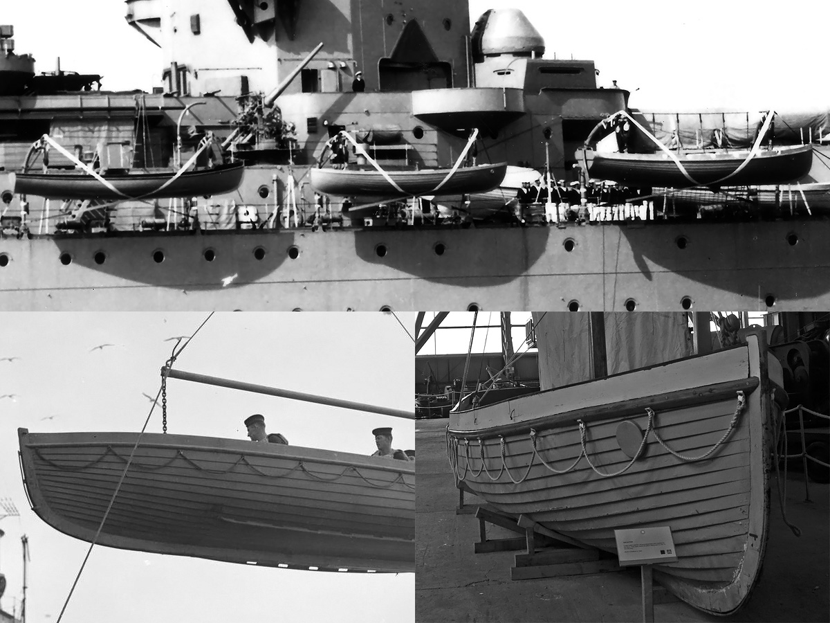
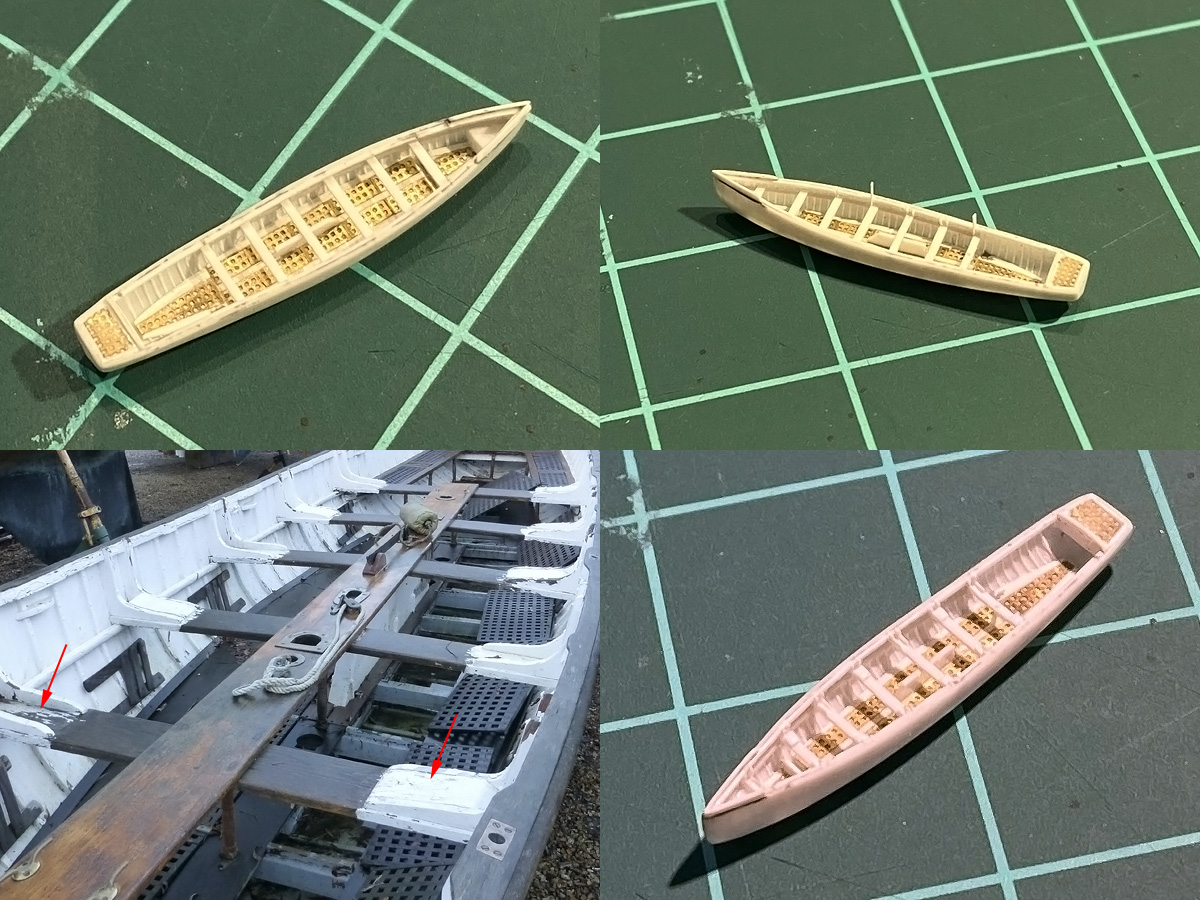
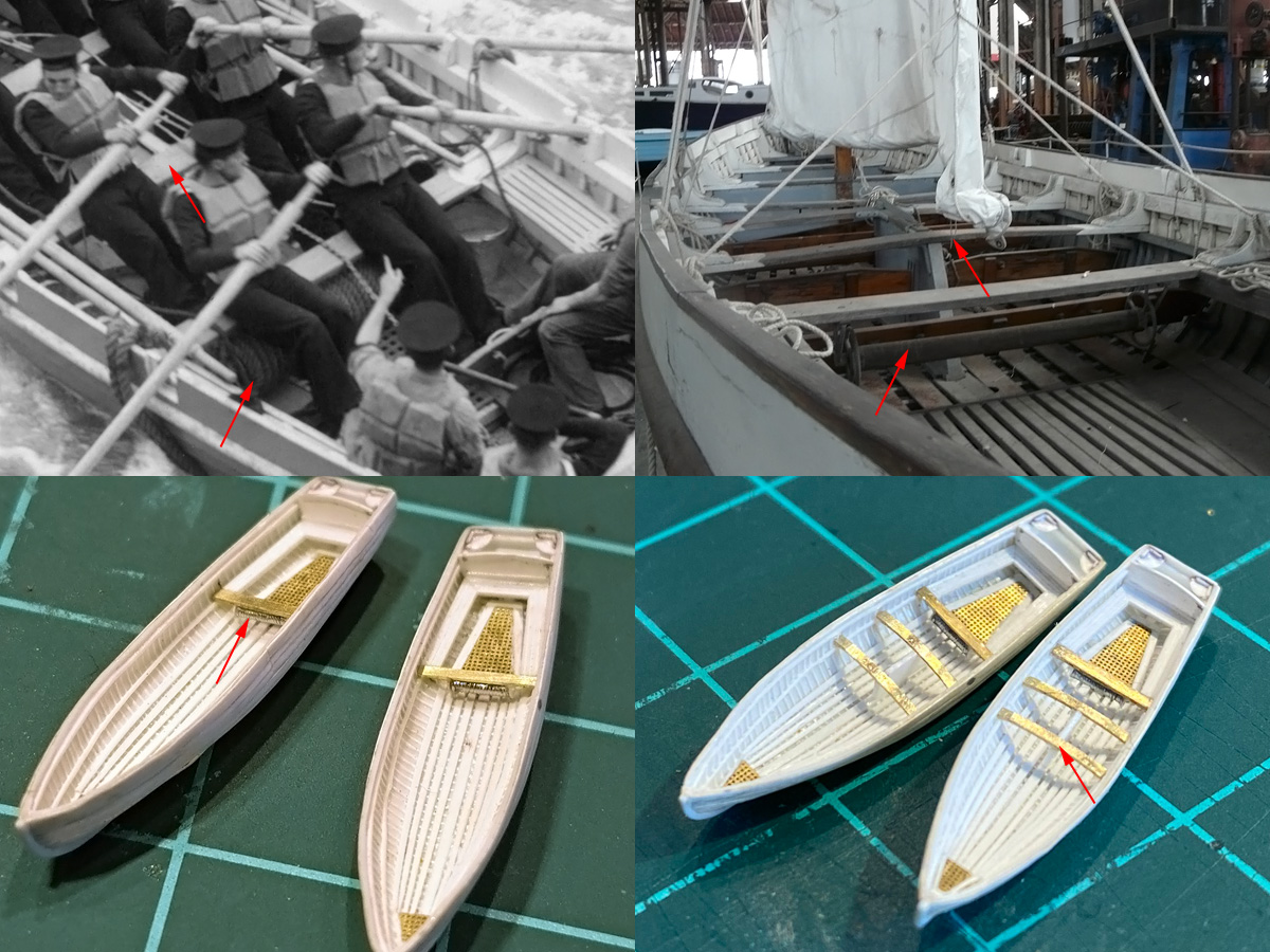
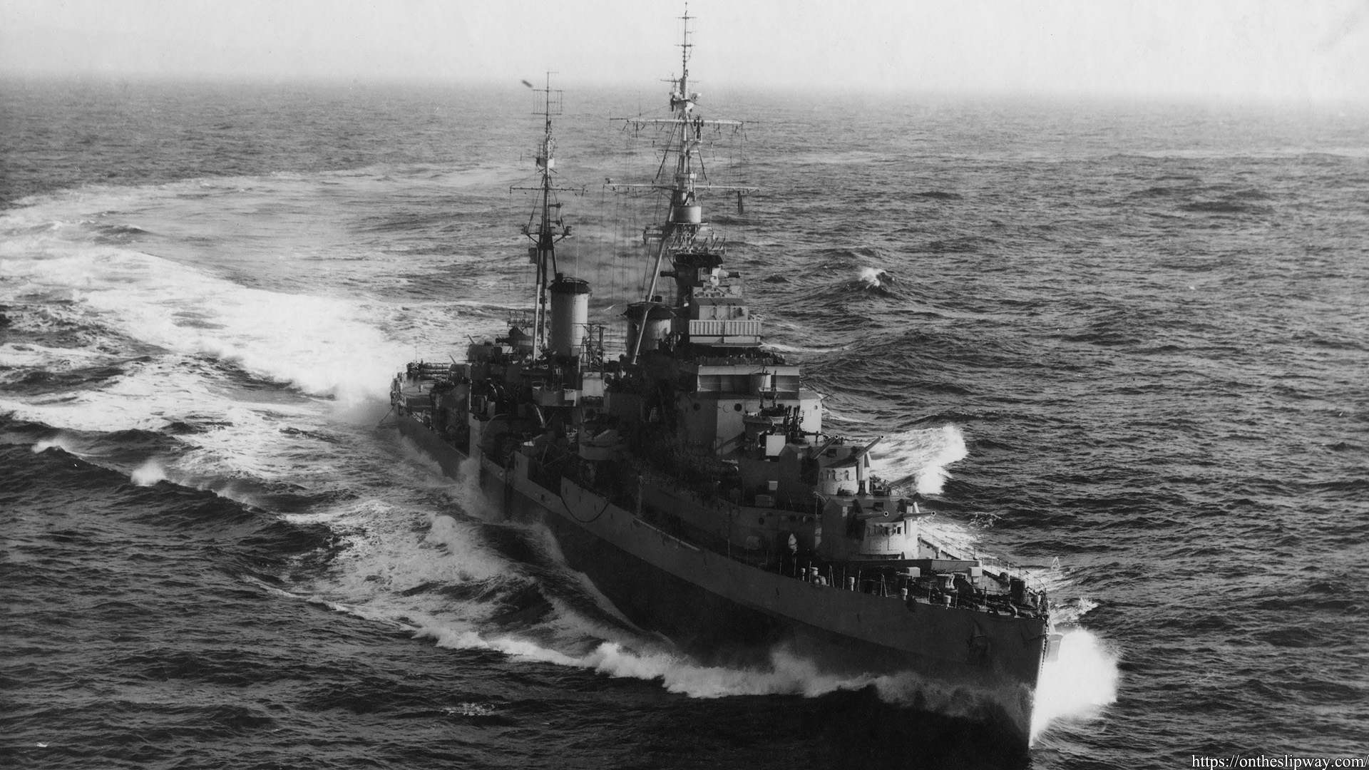
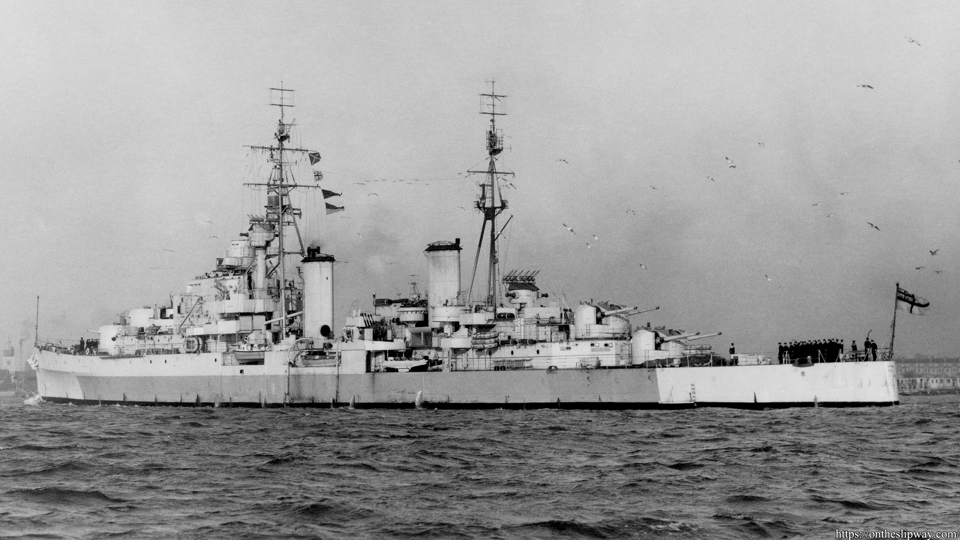
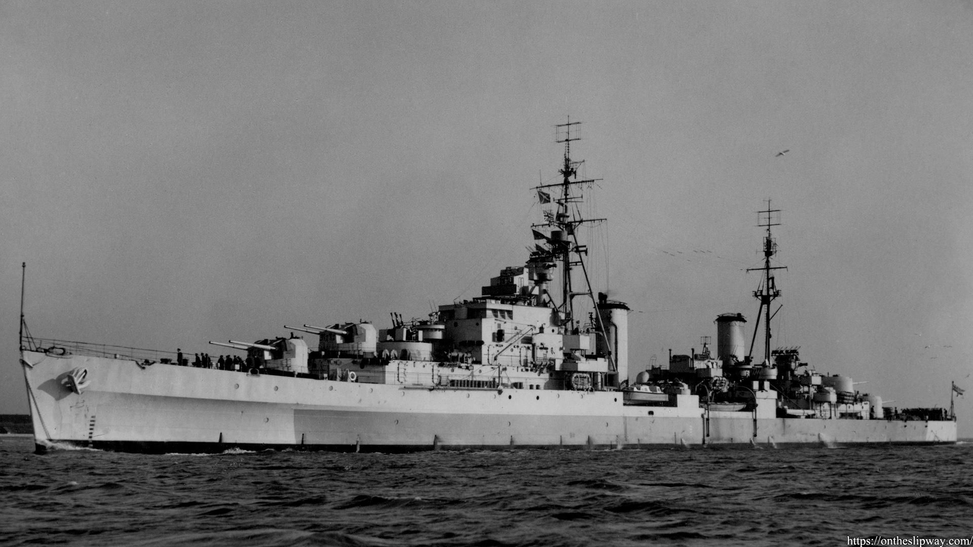
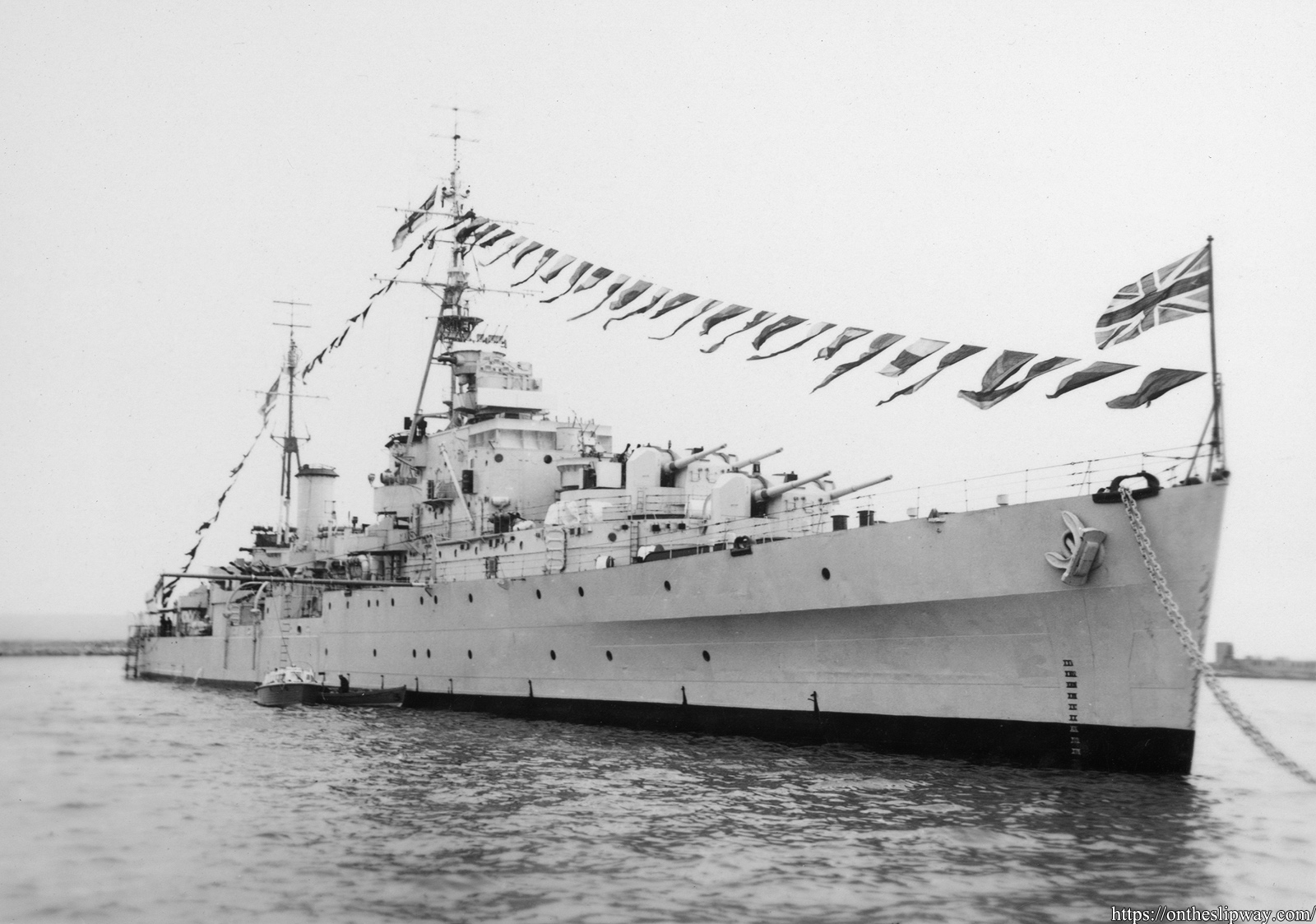
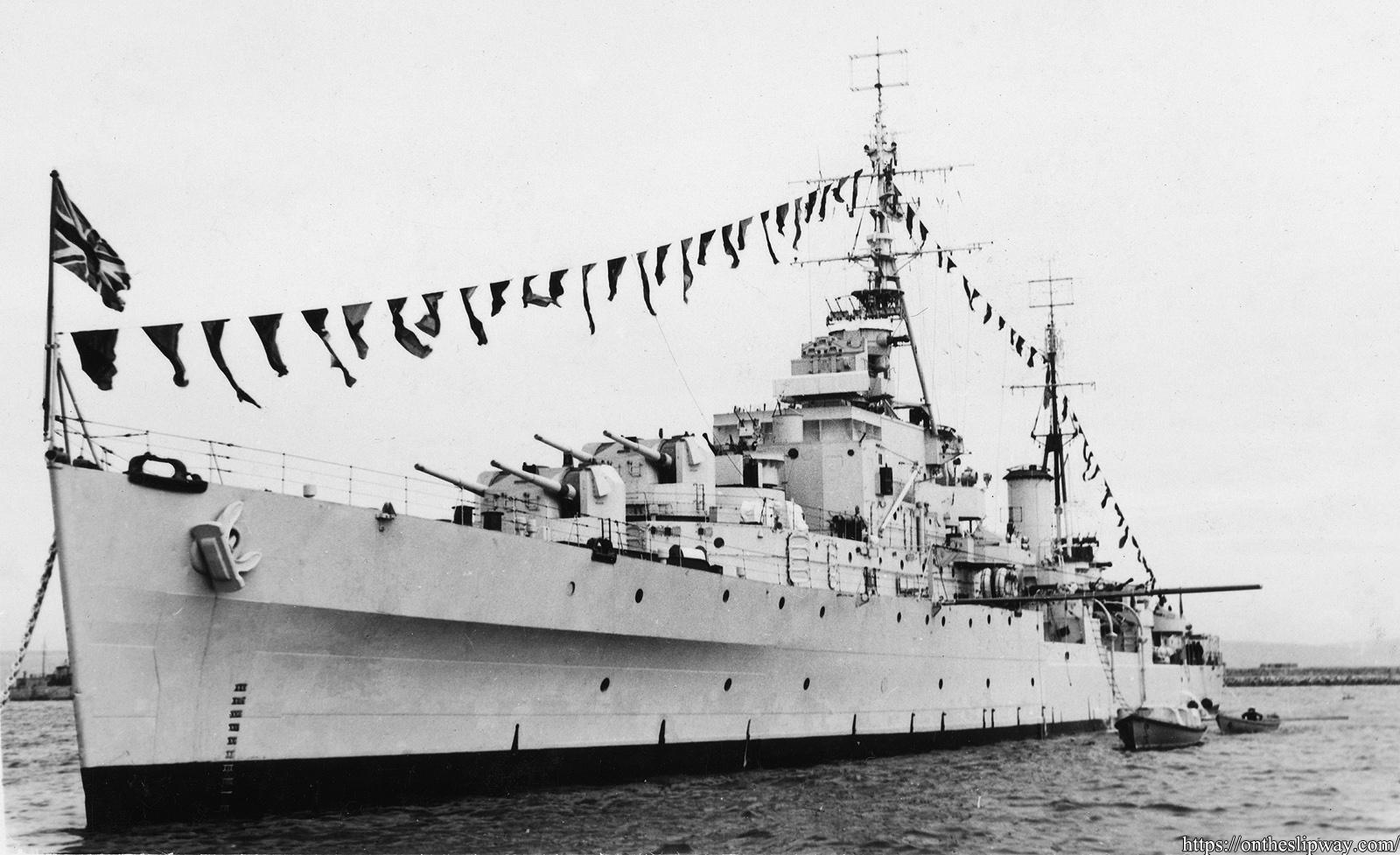
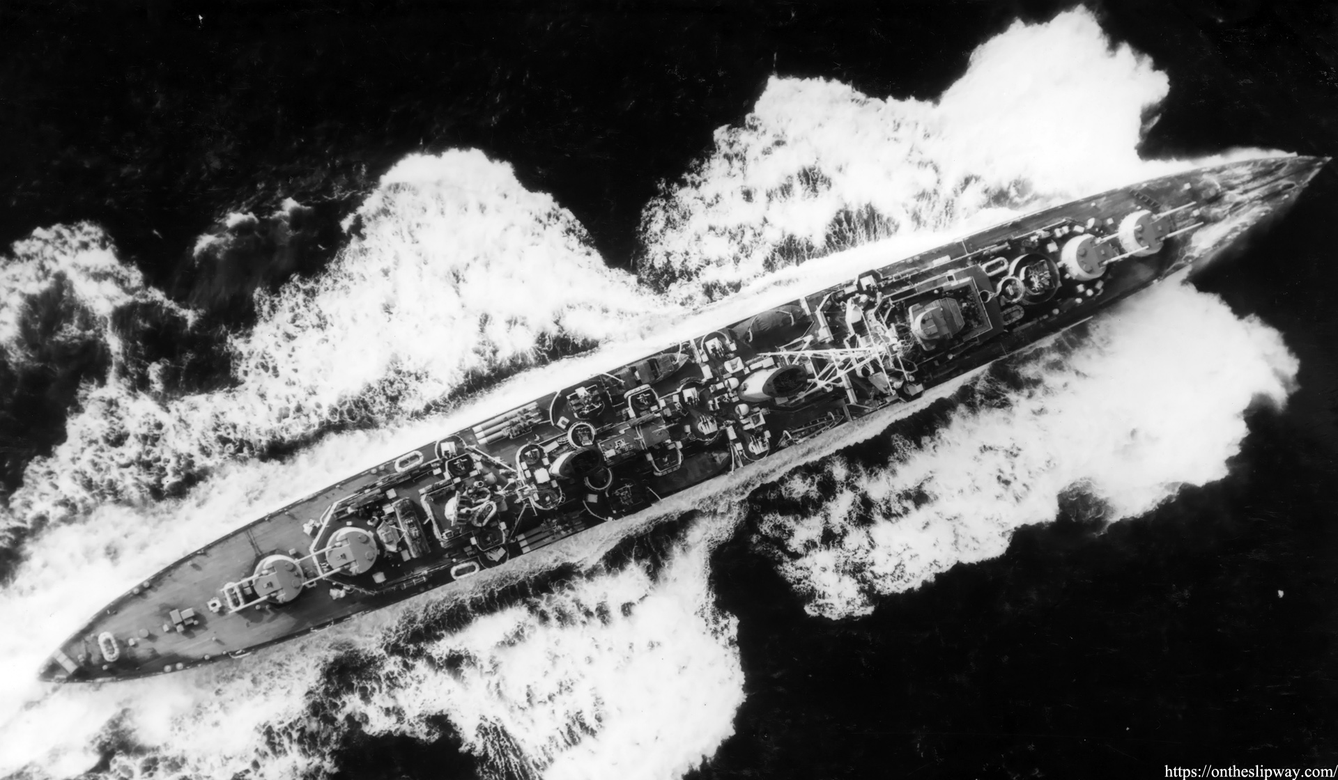
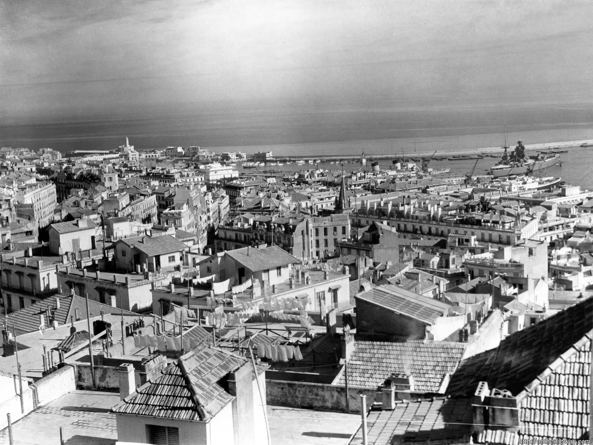
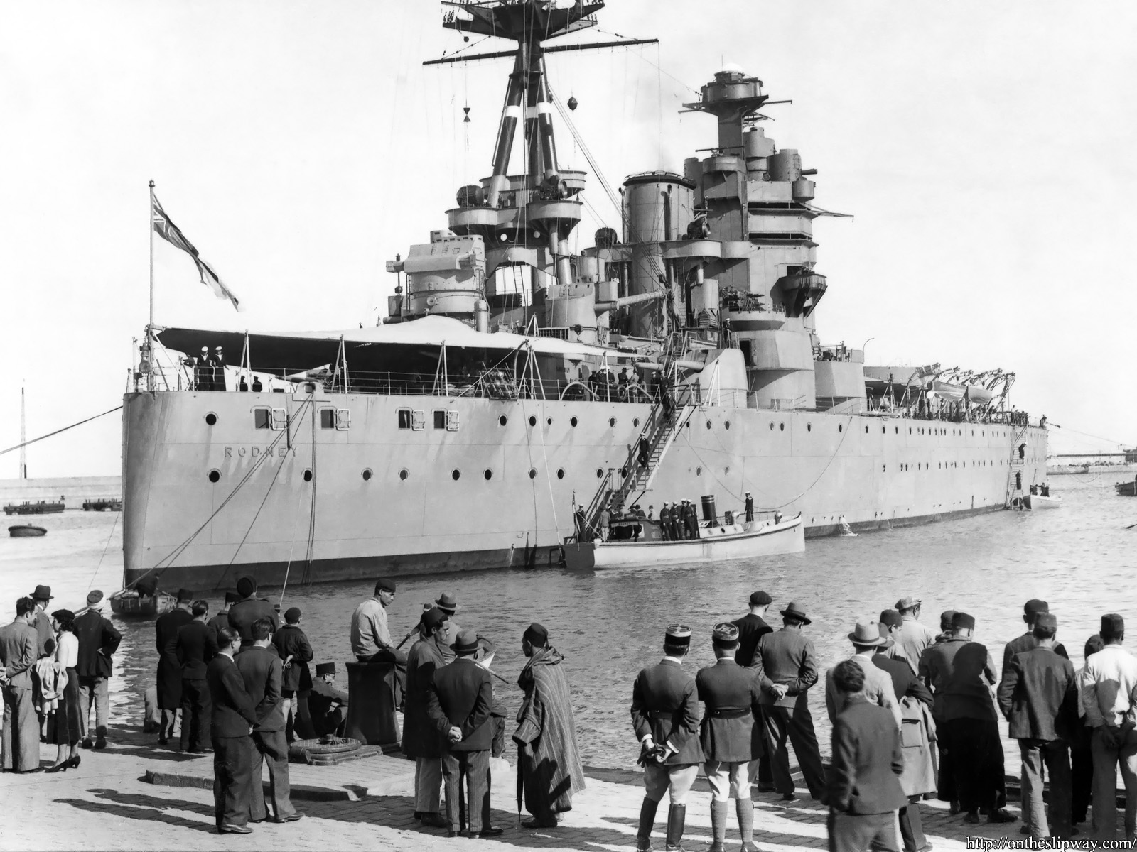
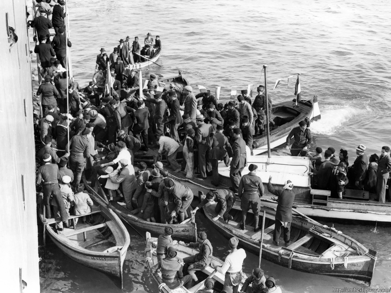
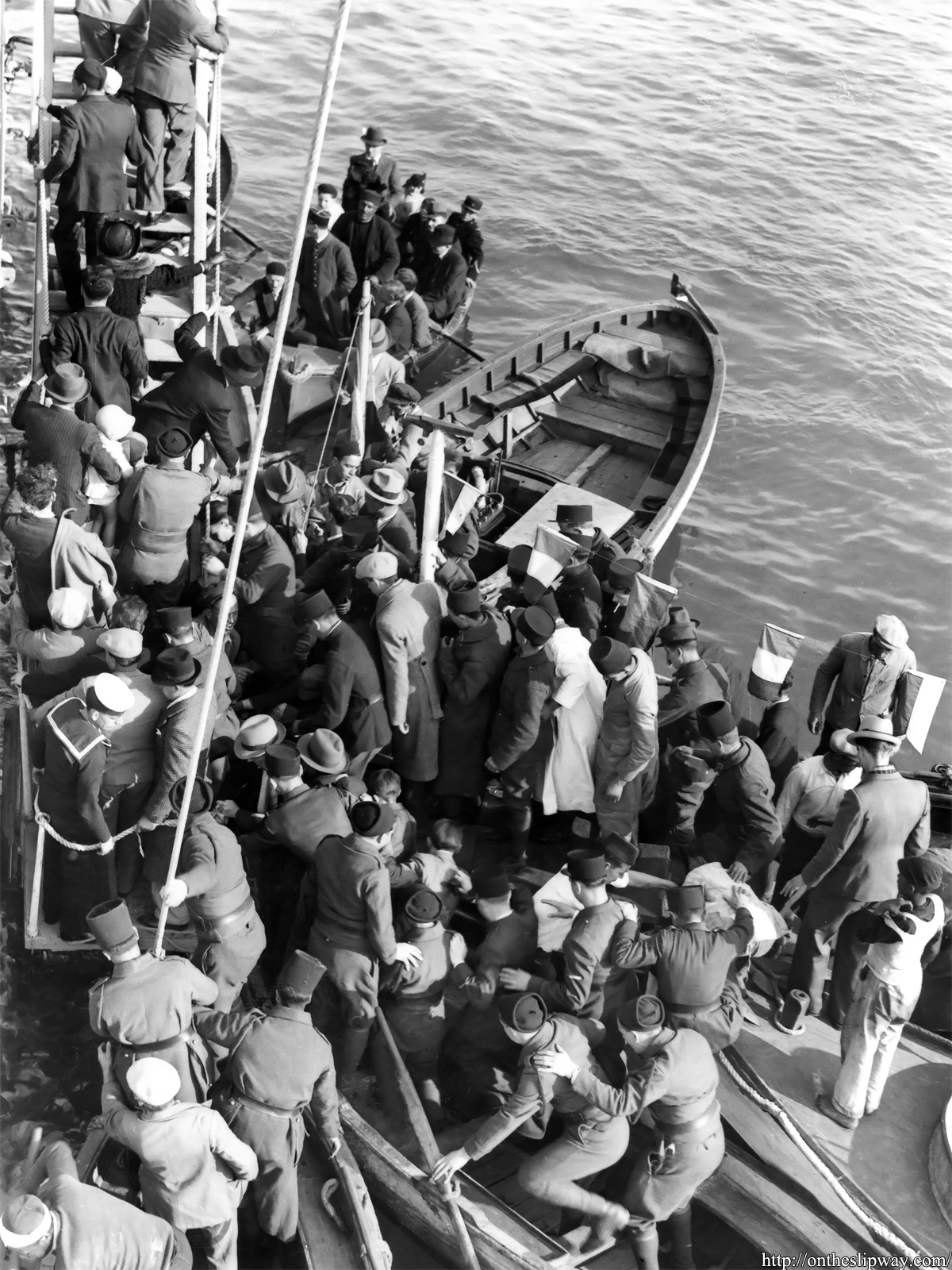
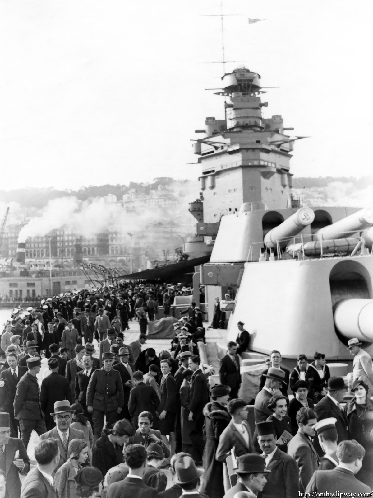
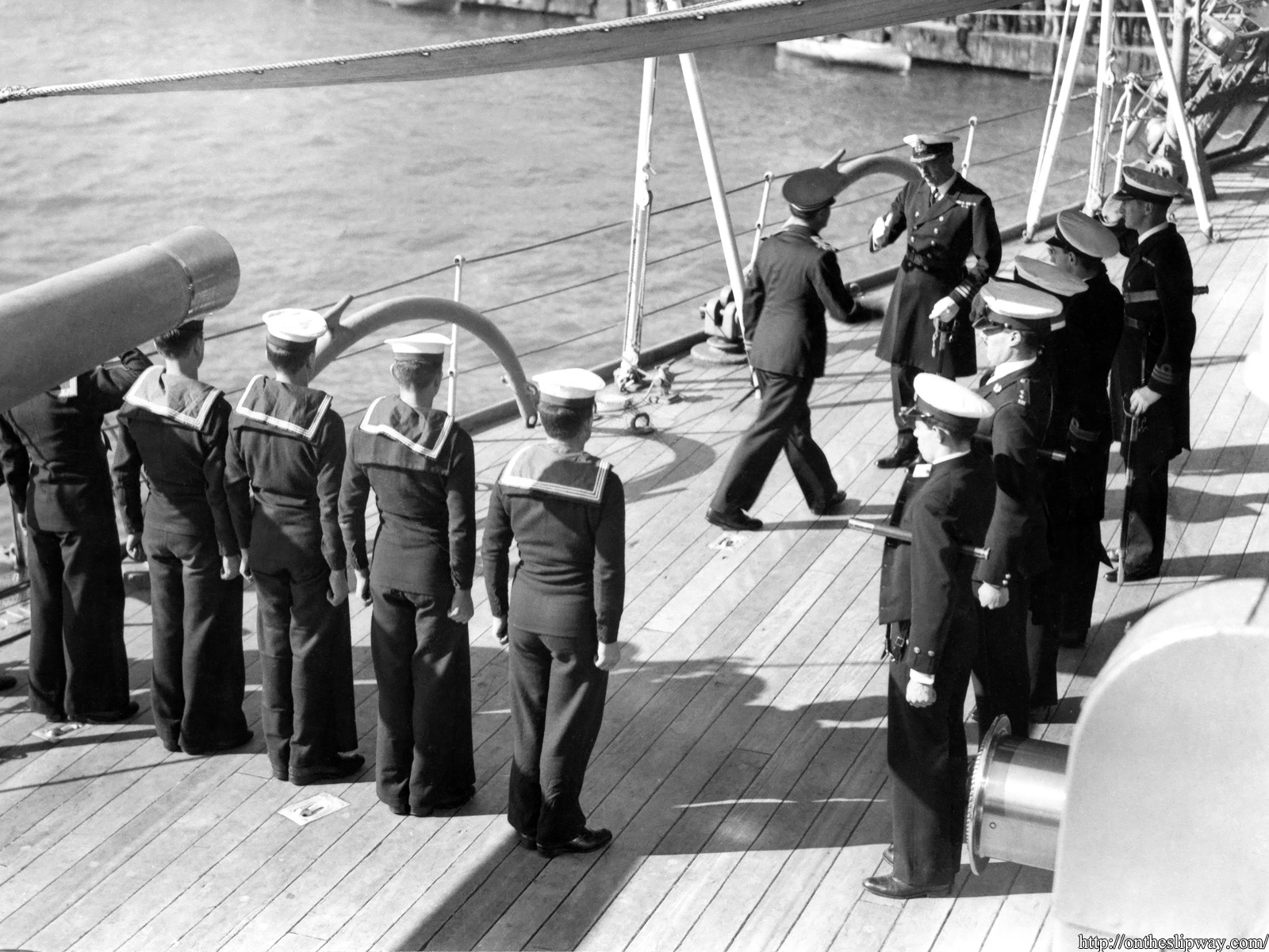
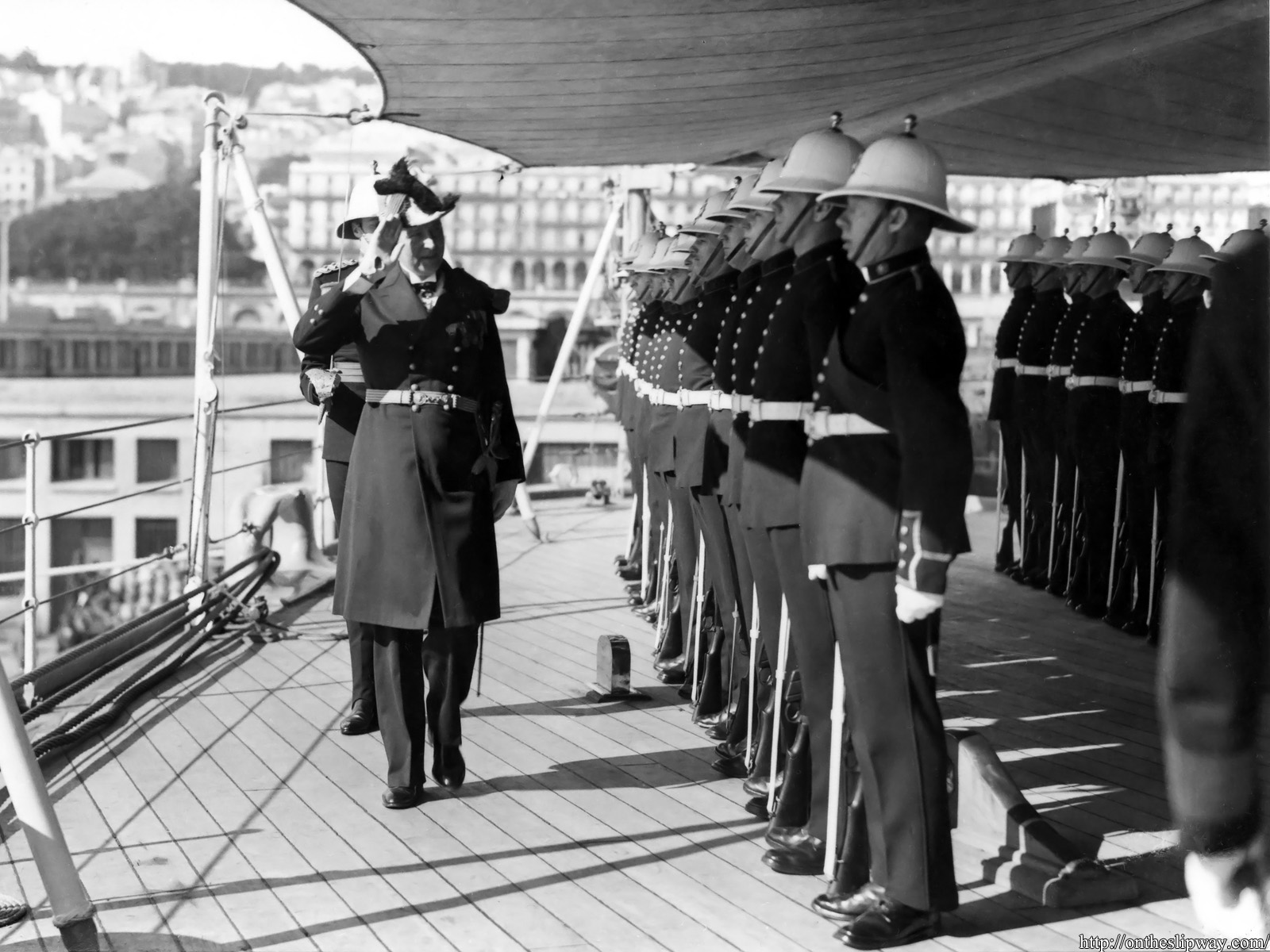
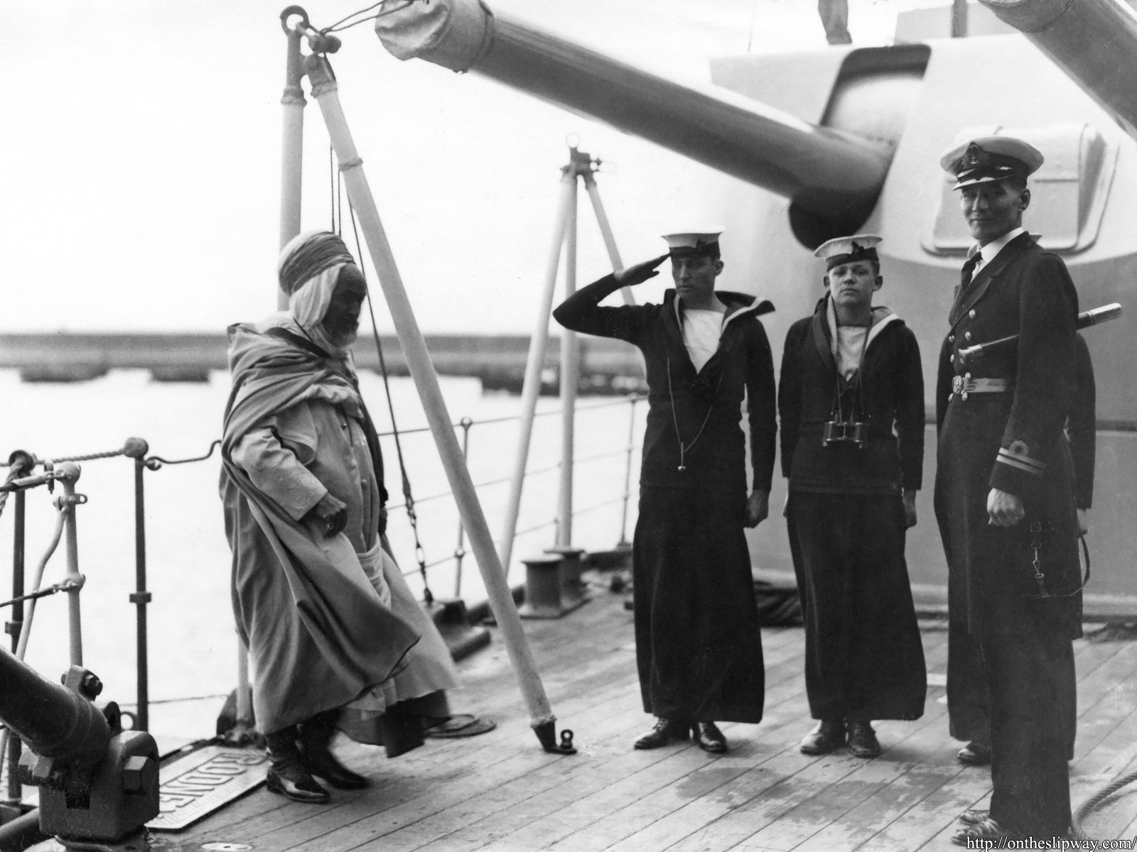
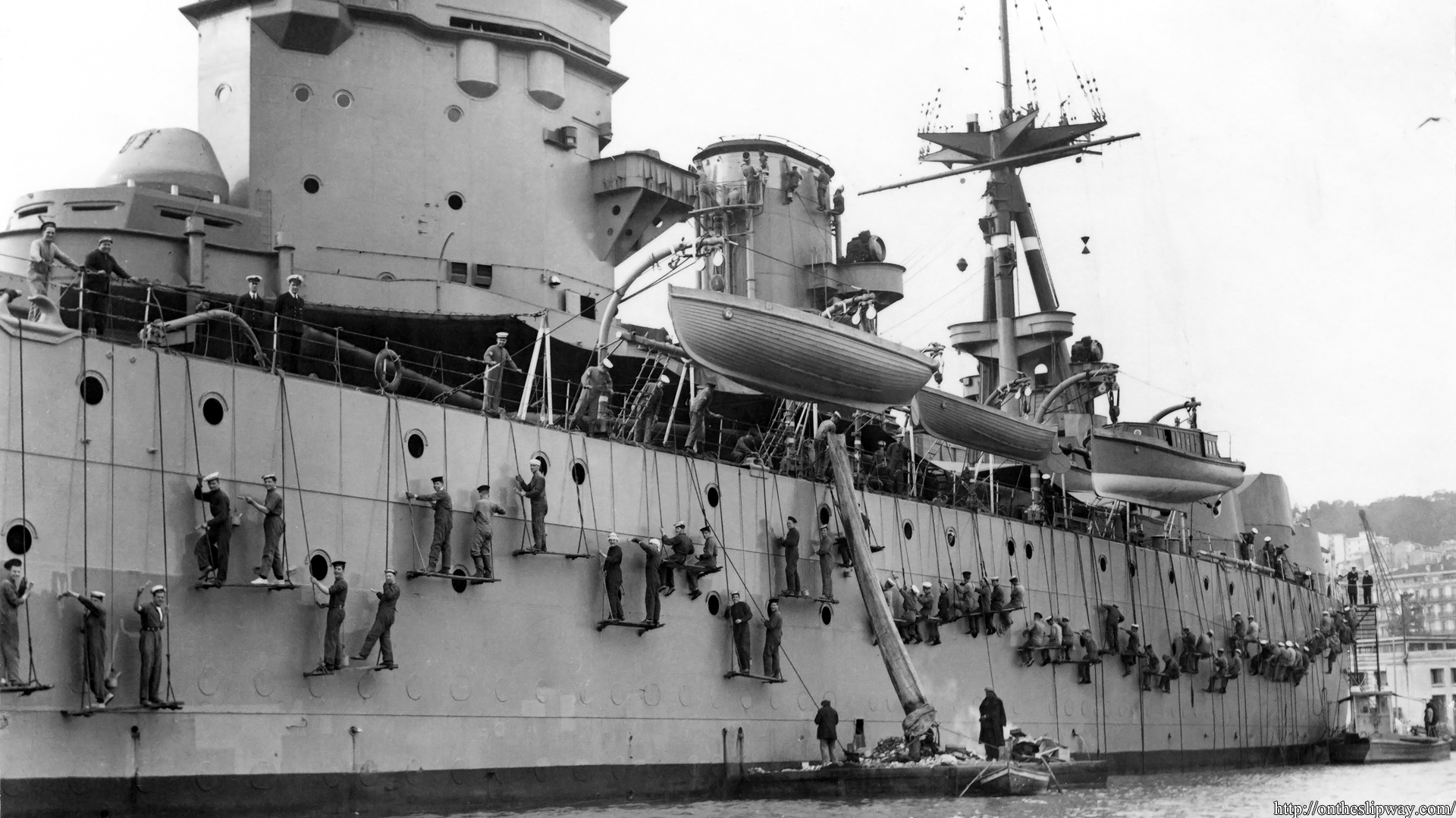
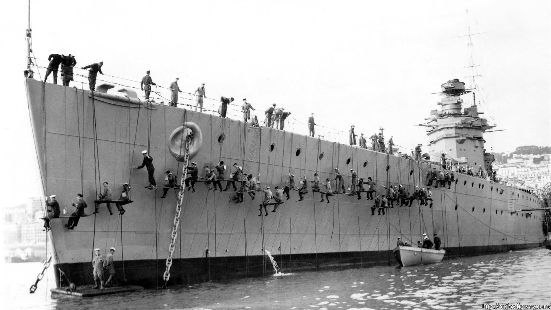
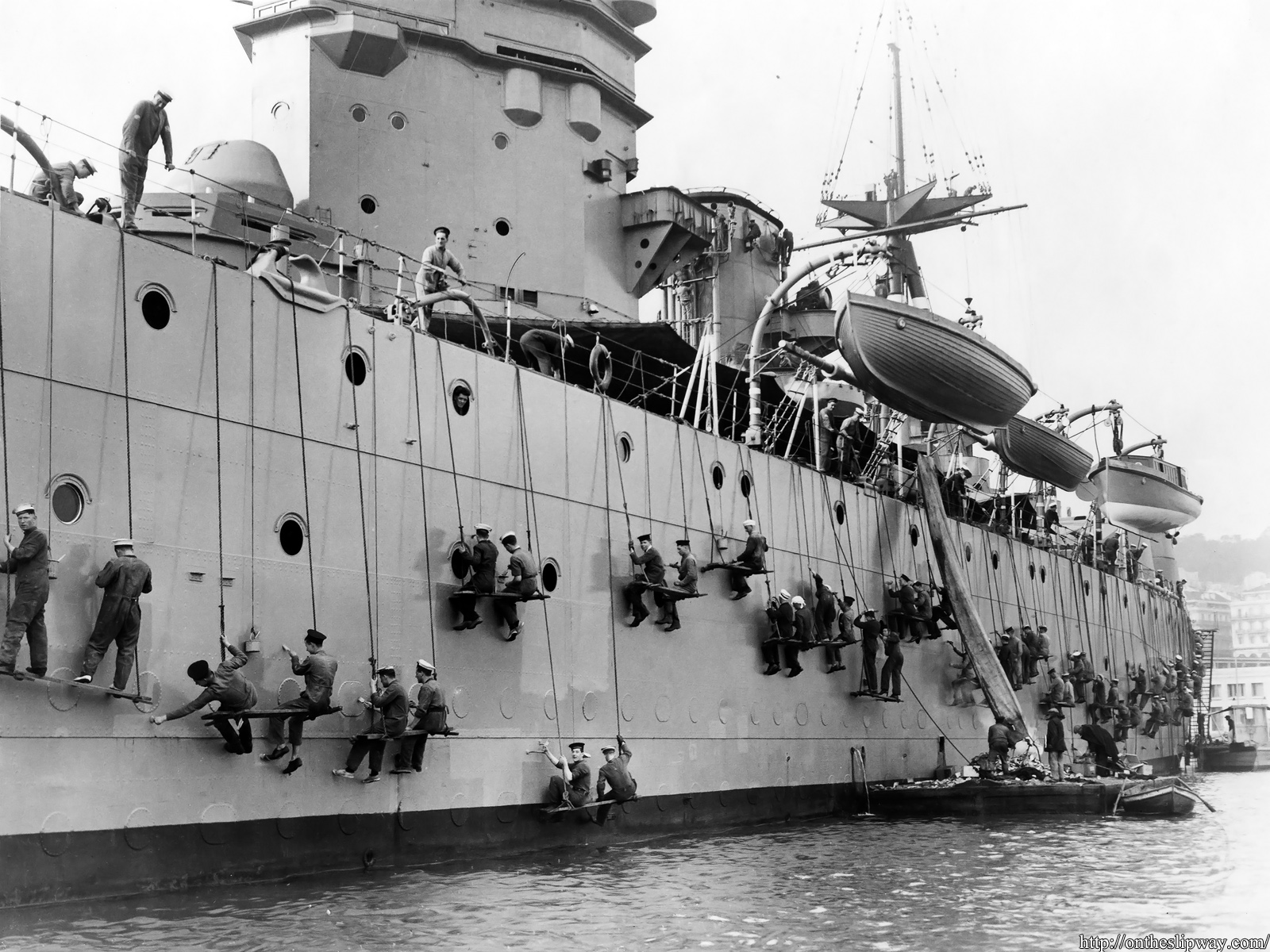
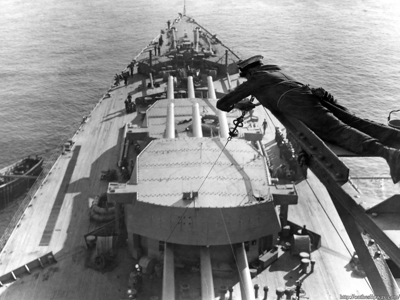
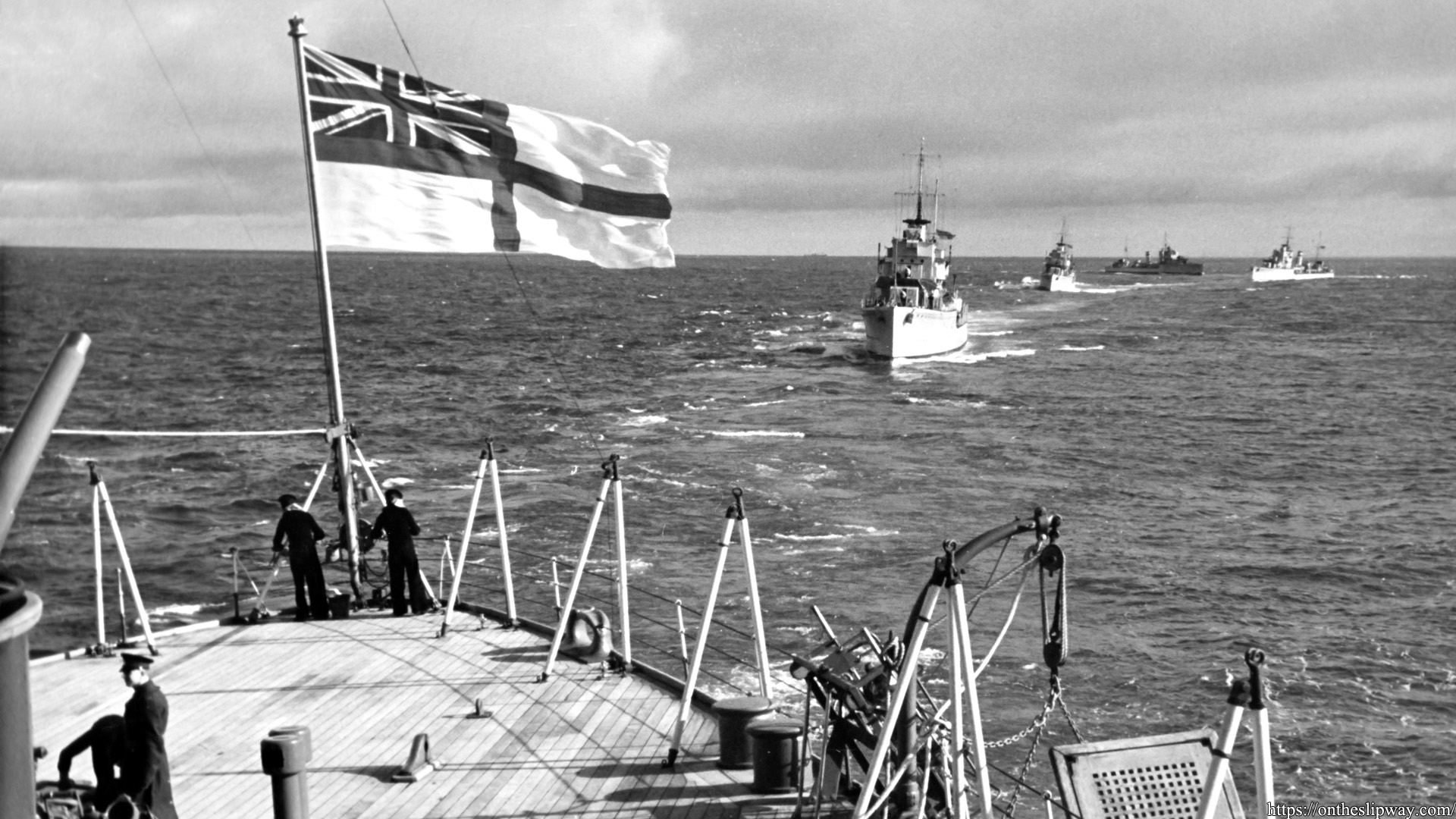
HMS Rodney hoisted a gig, a whaler and a cutter on special occasion for this very blog post; the effect of the clinker-built hulls is apparent (source bottom left, source bottom right). Would it be possible to add all the outer planks to the vacuum formed hull? I first performed a small experiment to find out if I could simulate a clinker-built hull by cladding the hull with strips. There were a few challenges. If you start at the bottom working upwards and add strips that actually overlap, then you may not end up with a regular pattern because of the very small plank width, and, the last strip will most likely not align well at the top end of the hull; the images below show that to be the case for the real boats. If you start at the top the alignment problem is ‘solved’ but you cannot add real overlap but decided that was the best approach. To get the overlap effect anyway I scraped the hull with a sharp knife just below each plank before adding the next.
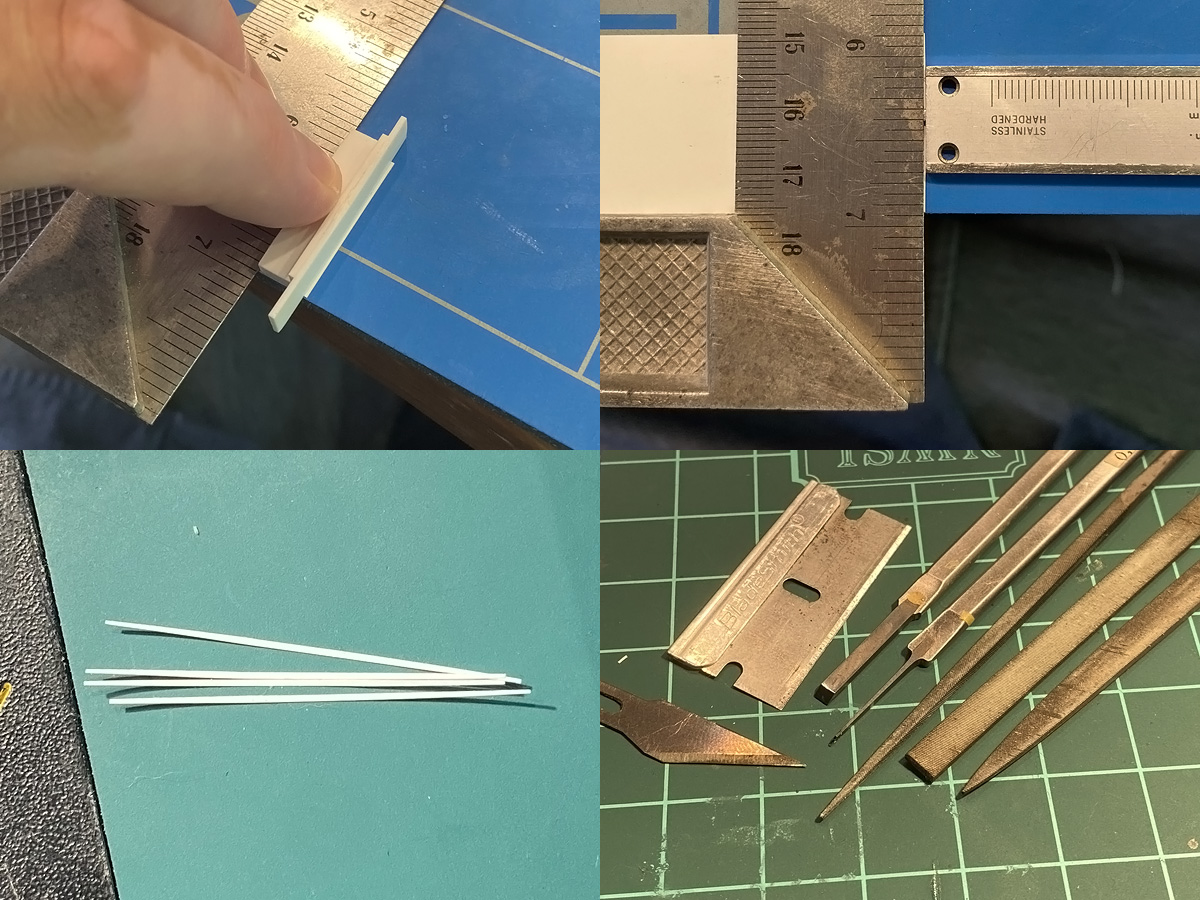
The plank overlap decreases towards the bow and stern and the distance between the strips should decrease. Judging by frame length at midships and at the bow and stern—and a quick plank count—I estimated that the strip width is about 0.275/0.35mm for the whaler/cutter, and that this width tapers by about 0.1mm towards the ends for both, so I made slightly arced strips. I made a simple cutting jig with a thick strip glued to the end of a small plate with a small 0.1mm strip in between . When I normally use a chopper and hold a strip pressed (slightly) against the stop, the knife cuts cleanly and straight down to the 0.1mm timbers for the gig. But with these curved strips the reproducibility was terrible. I resorted using the square ruler setting using the depth probe of my caliper for the right spacing. You need to cut each strip in few gentle passes to avoid it to start curling too much. Besides a few knifes I used a wide chisel for positioning and pressing the strip into place, a narrow chisel for carving away excess glue, styrene and ‘recovering’ the overlap effect on the outside if the carving in the hull wasn’t deep enough. A set of files are good for general correction work; the one at the far right has a safe edge—meaning no teeth—so you do not ruin the adjacent strip.
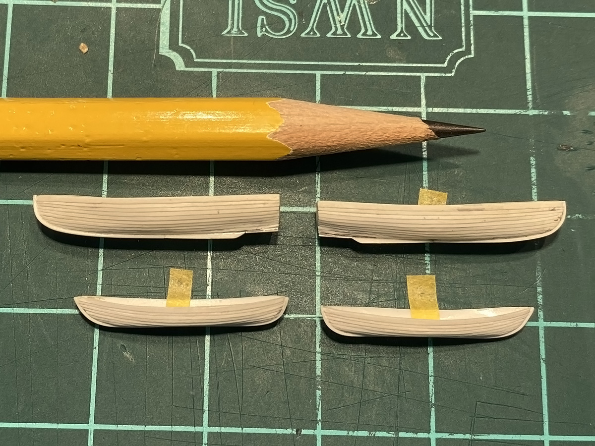
The strips were added at slightly less than 4 strips per hour and many pauses to let the glue set entirely. You need just the tiniest bit of ultra-thin glue and set the strip before the glue evaporates. A lot of correction and cleanup work was required afterwards as melted plastic occasionally ‘spills’ over when too much glue was used. For mild scratch repair used Tamiya primer applied by a fine brush. The planks appear a bit too large, but for the work involved I think the effect is perfect. The whalers are only visible from one side and one cutter will be placed in a barge, so I can hide some defects.
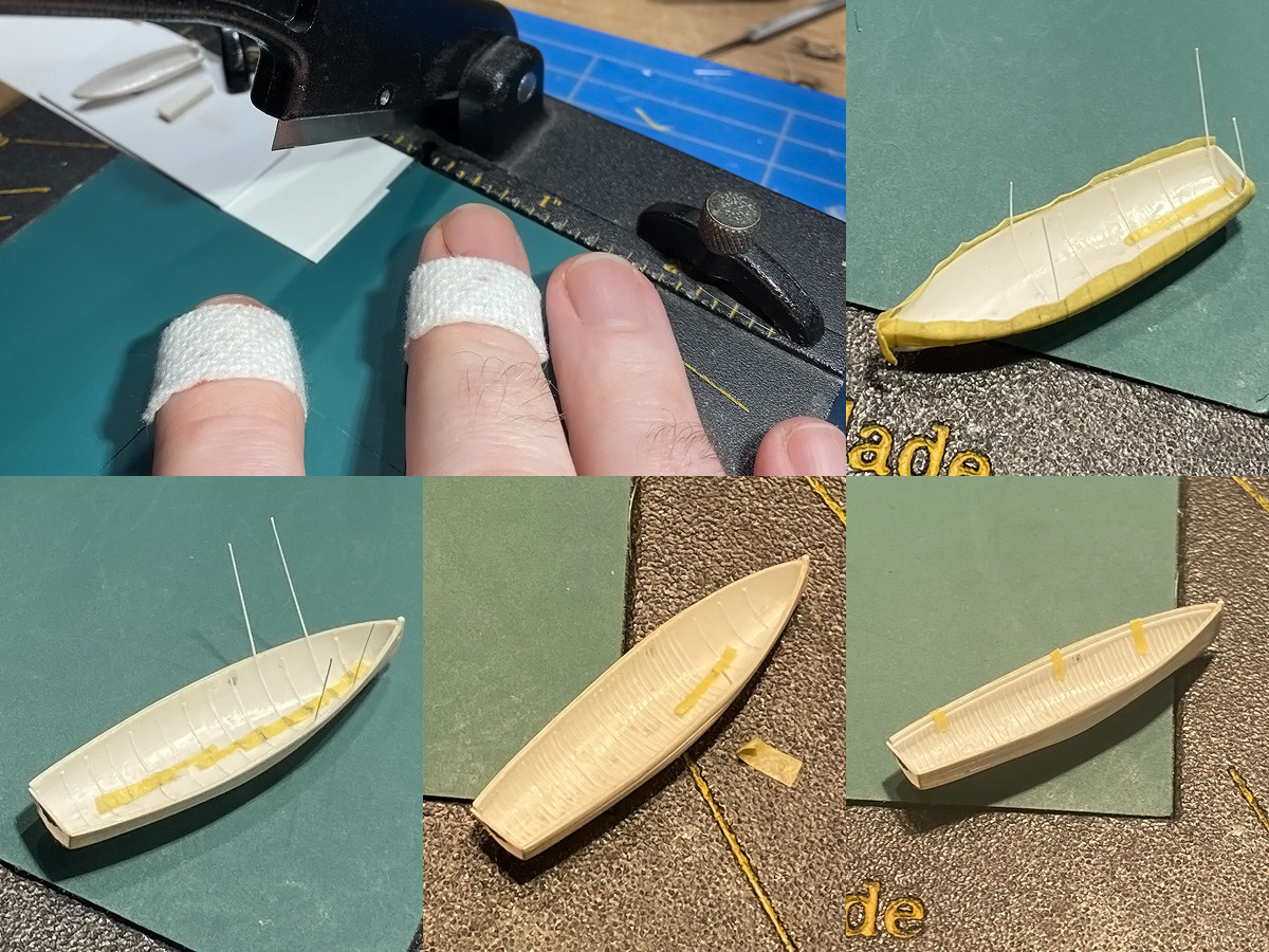
All the timbers were added next for the rest of the hulls. It took me about four boats before I felt comfortable with the recipe again. For these boats the floors aren’t gratings but a range of bottom boards, so the timbers had to be added in full . Top-left shows the chopper with a stop made from 0.2mm styrene plate to that I could get closer to the knife’s edge. A small “evacuation chamber” is added to that the strip can be pushed out during the chop, rather than run the risk of the knife moving outwards, and makes it easier to pick up the strip. And yes, I chopped both my fingers (twice; handle fell down while positioning the stop).
Tape with markings every 2mm are added next with the first strips added every 4mm. The top right image shows the tape running over the top of the hull, but was not a good idea; simply aligning the strip by eye from the side works better. Small strips of tape with markings are used to space the strips internally too. It’s critical to get the first strip in properly aligned in all directions; so it’s best to start in midships where curvature is at a minimum. The strips are then added and filled in every 2, 1 and 0.5mm; while each range should take more time, aligning becomes easier so everything goes a lot quicker. Badly aligned strips were carved out and replaced. The strips are decapitated and a small gunwhale strips finishes off the basic interior.
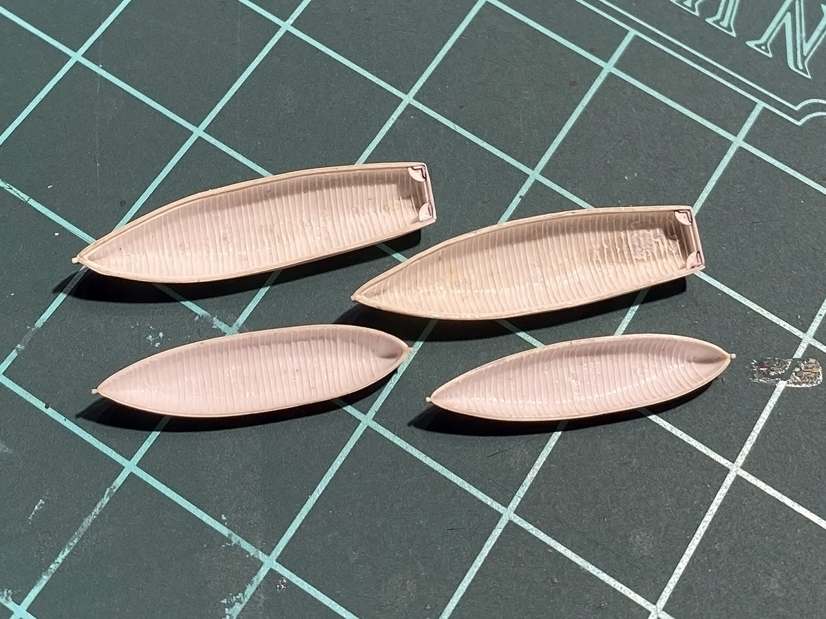
After a few days all four hulls were fitted with strips. Note that the hulls deform slightly with constant handing and adding glue.
Gunwhales and risings in place. The cutter’s floor in the far rear was added first with the risings glued beneath it; the risings should run roughly parallel to the keel but its near impossible to get any reliable bearing with these tiny models. For the cutter I eyeballed the first rising to run parallel with the keel; the other rising was put in place with the help of temporary thwarts to check if were parallel. For the whaler the rising runs between the stern benches and forward buoyancy tank but not on top/below them, so these details were added first followed by the rising.
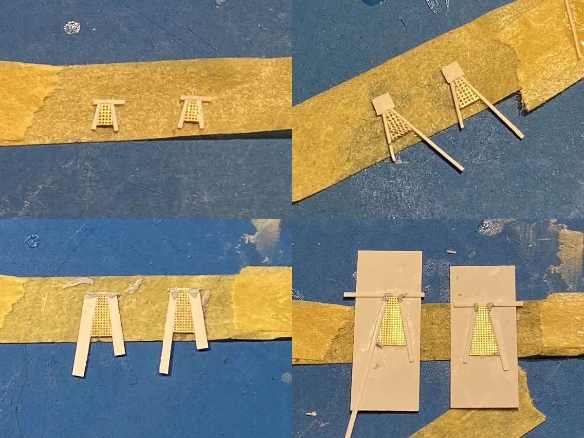
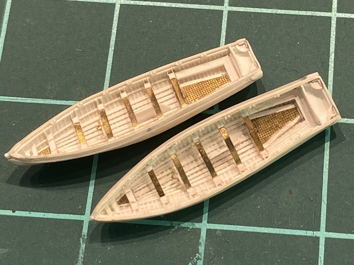
A range of gratings during construction; takes a bit of time to first get the right dimension of each of these parts but construction is then fairly simply.
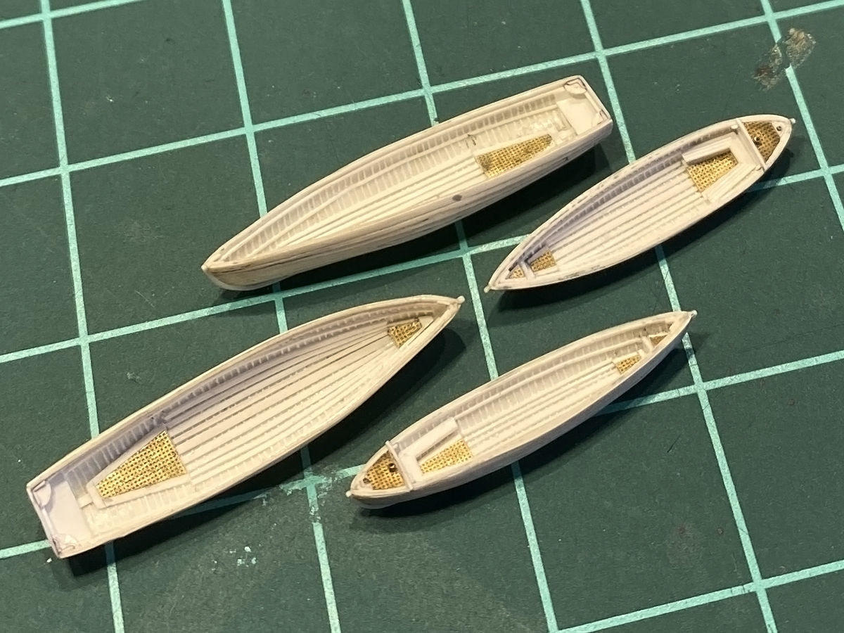
The gratings and bottom boards in place. I cheated a bit because there should be ten bottom boards per boats, but with 0.1mm spacing between the boards there’s simply no room.
After all this scraping , gluing of planks and timbers, and holding the part (I suppose), the hulls lost a bit of their form (beam too narrow): the cutter width was almost a full millimetre less than the plug. I decided to use brass thwarts to push the hulls back into shape; at first this resulting in one hull tearing itself along the length of the rising (probably the chiselling to create the plank overlap effect created a weak spot). After the repair I did some after-boiling of the hulls, reforming them as much as I could but this technique is far from flawless, oh well. The thwarts were milled from the Green Stuff Word’s 0.2mm flat brass profile and inserted into the hull. The hull is still a few tenths too narrow, but good enough. The grapnel reel was added below the aftermost thwart first; the next two thwarts are slight cambered curving over the drop keel.
All thwarts and knees in place, as well as all the rowlocks. One drop of glue escaped and melted the aft seating arrangement away (bottom cutter, top ) so that’s probably the one that is going to hold the gig; the rudder or oars will block this damage.
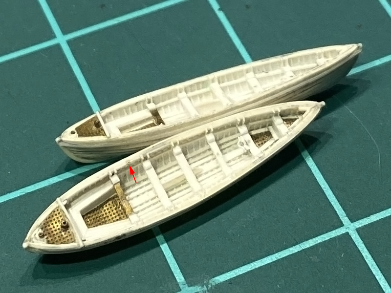
The whalers followed the same recipe, though I skipped the brass thwarts. I had a creative idea to add the sockets for the crutches; drilling in a 0.1mm hole wasn’t particularly easy so I tried adding small 0.2mm tubes by AK Interactiv (arrow). These tubes are so small that most of the pin vices or chucks cannot even hold them, so I bought a Tamiya’s fine pin vise (0.1-1.0mm). The depth probe of a caliper is used to set the right distance and a 0.25mm tube can be parted. These tubes were inserted into small nooks in the gunwhale using while glue allowing for positioning, fixed with CA afterwards, but I gave up after the first one.
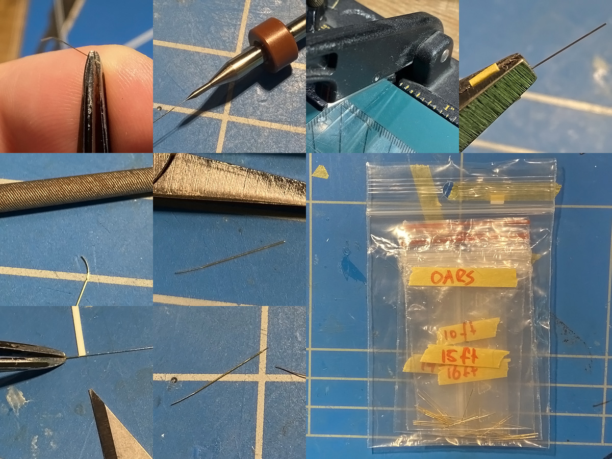
The manual of seamanship lists the number and length of the oars of all boats so this is fun to reproduce
- 16ft dinghy: 2x10ft, 2x14ft
- 27ft whaler: 1×16 ft, 4x17ft
- 30ft gig: 2×16, 4x17ft
- 32ft cutter 4x14ft, 8x15ft
- 42 ft barge: 4×15, 14×17
A range of oars was built using the same AK interactive 0.2mm tube I bought following a great tip by Stefano who builds even finer models than I do, clear one end by careful sanding and opening the tube by 0.1mm drill. Chop to size and flatten one end; I added a bit of tape to the pliers ti avoid flattening the tube too much and to use as a ‘depth gauge’. Add a curve to the end by rolling the paddle with the end of a needle file and flatten back a bit. Insert Albion Alloys 0.1mm wire at the other to simulate the handle and cut to size using a strip as a reference, fix with a droplet of CA. Put on Tal & Groethuysen’s 7-CD Schubert recital and repeat the oar process 75 times.


