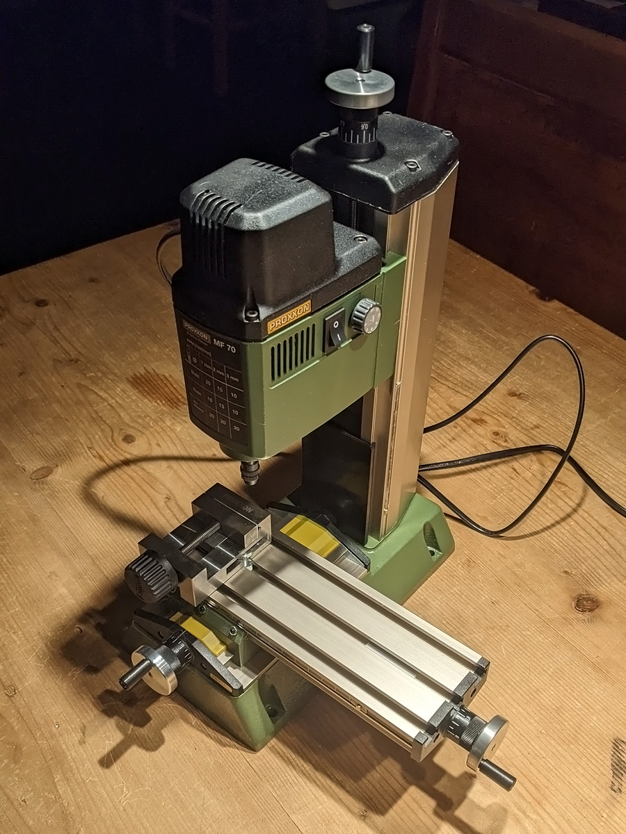
I just bought the Proxxon MF70 Milling Machine (27110), a tiny machine that can be upgraded (or bought) as a CNC machine and offers a much higher rpm than my drill press or lathe: it goes up to 20,000 rpm. I was never able to drill anything below 0.5mm without drills breaking and more or less gave up on that idea without a watchman’s lathe or equivalent, until Marijn van Gils showed his brand-new MF70 could drill almost to 0.1mm in brass (See his HMS Victory Vs Le Redoutable build). As the mill is quite affordable and I no longer have to pump all my savings in my recently completed audio project, I bought one as well.
So I did use the Drill Press with a compound table (27100), a precision machine vice (24260) and a nice dividing head (24264). But, the rate of revolutions is low and the entire setup is quite flexible and as such not precise. More important, it does not have a proper collet system but uses a large three-jaw chuck that is inherently terrible for fine work.
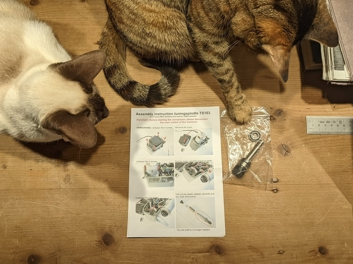
Imagine my surprise that the MF70 does not have a proper collet system either; it uses the Micromot collet system. That’s fine, but these cannot old larger objects such as Proxxon’s own edge finders. For my small lathe, Proxxon failed to deliver a proper collet system for the tail stock too, though that was solved by brutally cutting an MC11 ER11 collet chuck. For the mill this is not an option as the spindle doesn’t use an MC11 system, but after minor search efforts I found a replacement part at USOVO; a new tuning spindle with an ER-11 chuck and it even comes with a small installation manual. Rejoice!
I do wonder why Proxxon seem to be content with their tools not being able to use the entire range of tool mods and expansion sets among them, but at least now I could use the Edge Finder Set (24434) that doesn’t fit the original MF70 to align the vice properly and to help finding, well, edges. I did perform some tests with the Micromot collets and these did hold some of my drills perfectly centred, so I can image some people not needing the ER11 collets. I added an extra collet set in a nice box (24154, but you better buy a set with more collets for less elsewhere as this set contains only 7) plus an additional vice (the vice vice). With these options the mill became roughly twice as expensive and I forgot to buy cutters as these are not included—not even one—but small cutters can be bought as small as 0.2mm at other stores. The mill did come with a cross table (27100) and a set of step clamps (24256).
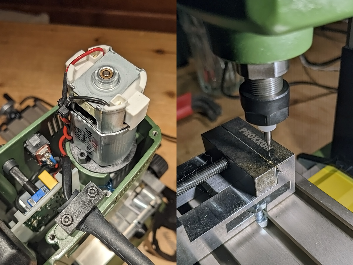
Installing the new spindle took about half an hour. I used my sturdy Gorilla-proof 1.5mm Hex wrench the remove the motor plate screws that have been tightened very well and T10 (I think) Torx driver to remove a screw holding the spindle in place. The Usovo spindle comes with two bearings but I kept the bearing of the existing spindle. The set does not come with a tool to (un) clamp the nut or hold the ER11 spindle; I had one for the ER-11 tailstock of my lathe so don’t forget to order one if you purchase this new spindle. You may also want to order a 3.175mm ER-11 collet separately, the default size of many of my drills.
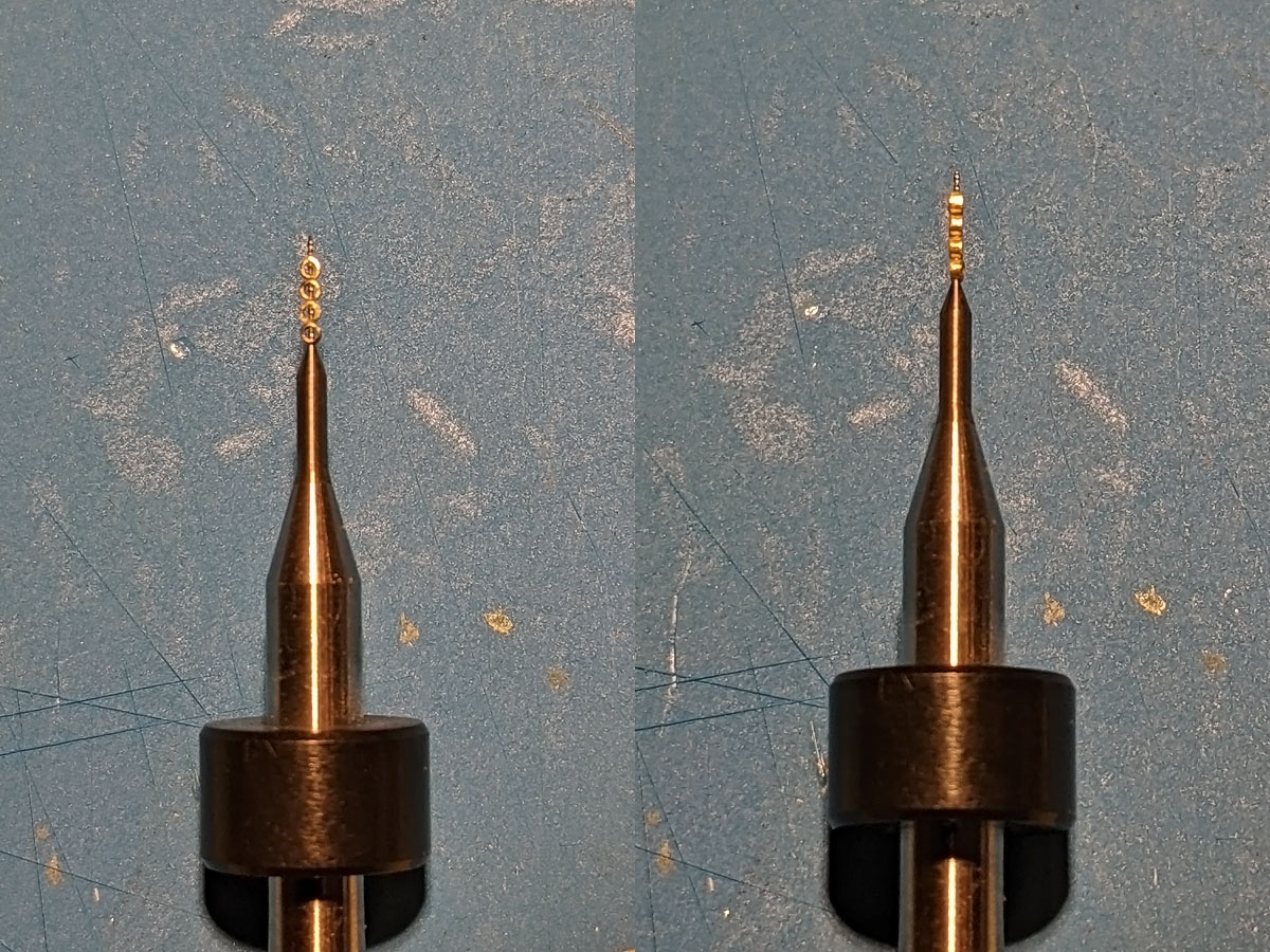
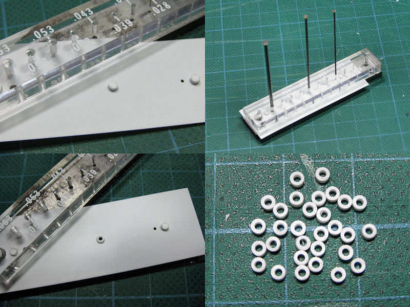
First some experiments starting with something large: a 0.2mm hole through a 0.3mm slice of a 0.7 Albion Alloys tube. Zeroing the drill position is something you’d rather do with the edge finder (that hadn’t arrived at the time of writing) and still on the very first attempt the MF70 left my drill press in the dust. The main causes for inaccuracy went into inconsistently clamping the work piece in the vice and parting the small ring using this method.
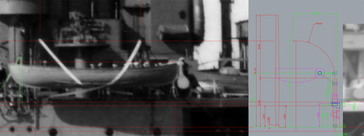
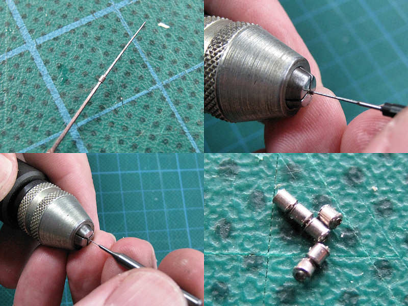
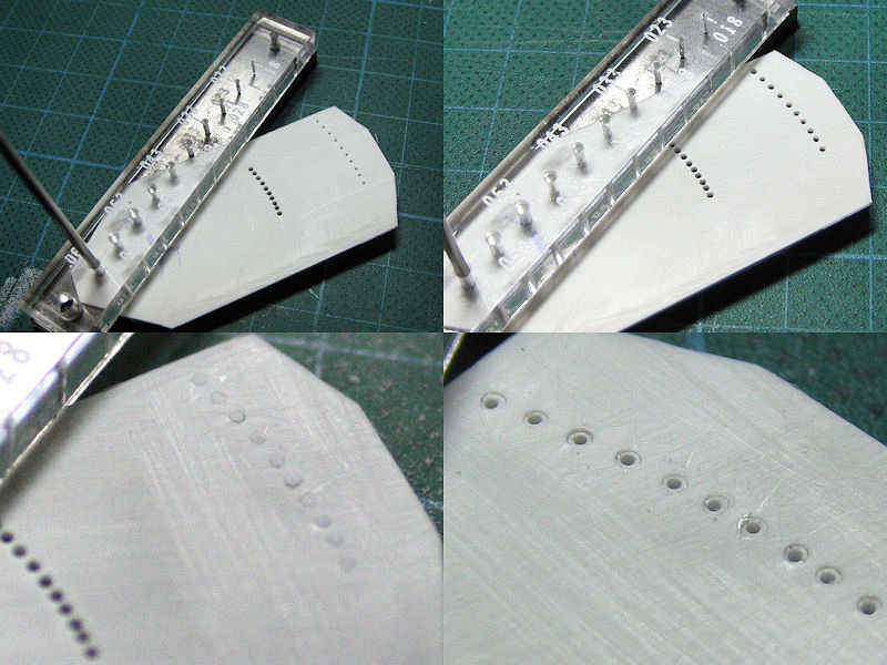
My intended targets were the davits for the 27″ whalers. This is a terribly delicate section of the model and it would be really useful if the entire assembly could be mounted by pins into the side of the superstructure when the model is more or less done. These davits are not only very thin (0.5mm rod at the centre, filed down to 0.3mm at either end plus a series of 0.7mm rings) but are also angled in slightly inward by 12 degrees. Here drilling in and soldering mounting pins and etched parts to the davit would be very useful; soldering the gripping spar to the davits would be even better as then the whaler could be glued to this spar; rope work can be added last minute. So each 12mm davit needs to be drilled in four times, two pairs of holes at perpendicular angles so the work piece needs to be rotated at least once.
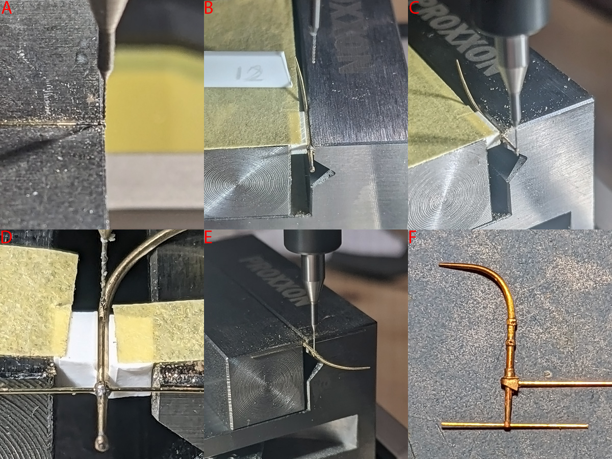
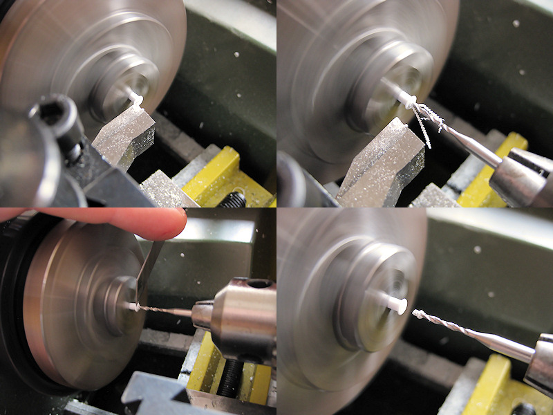
With the ER11 chuck still in the mail I started with several different techniques that are all bad. I bent the davit before drilling it, worried that when bending after drilling it may break at a hole as some parts did. The drill was centred by eye (A). Bending first makes it difficult to clamp the davit so I used a block of plastic and a small 12-degree alignment plate (B). Soldering the rings before drilling is easiest, but when traversing in steps of 0.1mm you really need to solder all these rings perfectly if you want to hit them dead centre (C). This went well but not really something to recommend as the part will flex. When the part needed to be rotated 90 degrees I tried two plastic blocks and re-centring the drill (D); this is awful as the part may slip (slide or rotate breaking the drill) and your reference is all over the place. Reversing the part—using a bit of rod to eyeball the angle—went better (E); not really good either with the part poorly supported. The prototype did work out nice though (the one that survived that is), after the rings from the first exercise and some etched parts where added (F). With the part flexing and overall experimentation I lost quite a few drills but it was a great introductory exercise.