
The main crane derrick is operated from a platform at the base of the main mast. Two large winches are below the boat deck in the boat hoist compartment. Two cables run through pipes in the deck to a series of pulleys at the top of the tripod. One cable goes through the lower pulley and a pulley in the end of the main crane derrick, hoisting the boats on and off board, the other cable goes back and forth five times from the middle single pulley and two double pulleys—one at the top position on the main mast and one at the crane derrick’s end—setting the main derrick elevation.
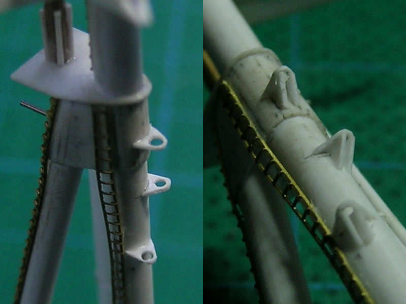
The drawing in the Anatomy of the Ship series isn’t very accurately depicting the construction of the pulleys or the correct alignment along the main mast. The new position was determined using a series of pictures from this particular area. I started by adding the lower part of the frame of each pully, with a few difficult-to-cut parts. A series of supports are added to the frames, but as the wiring runs through these supports to the boat hoist compartment, and a double set of these supports is seen on the photographs.
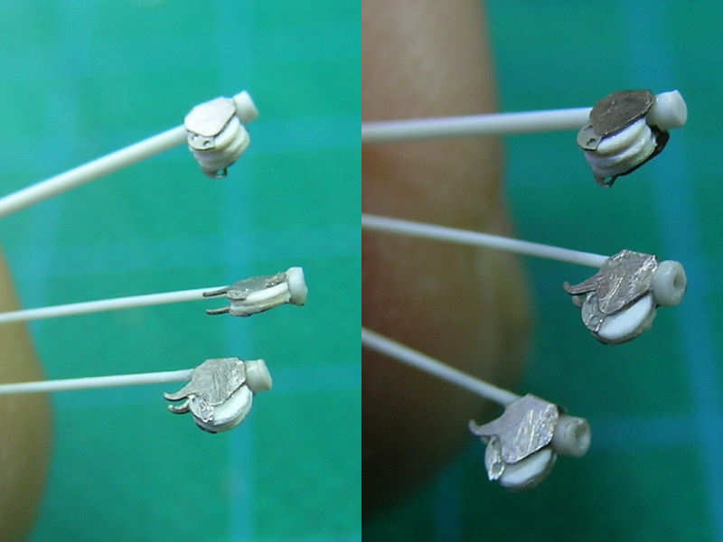
The pulleys are an etched part plus the pulley themselves, made from 0.13mm Evergreen styrene. The pulleys rotate along an axis, but the wire as to be able to run downward with the derrick swayed to the side of the ship. I don’t know if the wiring runs through the pulley support, but it seems a logical approach. These supports were later replaced by steel tubing.
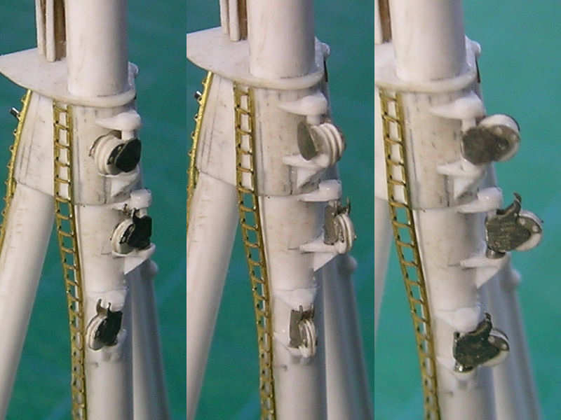
All pulleys in place. Note that the pulleys can swivel, following the position of the main derrick. The wiring, when the model is rigged, can still go around the pulley and through the supports. Not that I plan to have a fully operational 1/350 main crane, but it does allow for the use of only two wires to rig the entire crane (as in the real thing) and for alinging the lower pulleys toward the end of the main crane. In the outboard position, the pulleys are at an odd angle but that won’t be visible with the derrick in the stowed position.
