The pom pom director Mk I is an elusive director. The Mk 1* was fitted to Rodney & Nelson, Hood, Furious (2), Royal Sovereign (2), Barham, and locations at Fort Cumberland, Devonport, and to Vickers-Armstrongs. The Mk I** was also fitted to Hood, as well as Barham, Ramillies (2), Repulse (2), Nelson, and locations at Porthmouth, Crayford, Chatman, and to Vickers-Armstrong. The differences between the versions consists of a cross wire foresight and some additional knobs although the older units were updated. The differences with the MkI** are unknown to me.
Knowing where these directors were fitted doesn’t really help in finding images. The location aboard HMS Hood is known but there are no photographs. Fortunately, Admiralty record Adm 186-316 in the UK’s National archives, entitled “Pamphlet on the director for the 2-PDR “M” Mark V Pom Pom” from 1932 contains a few pictures and diagrams. I ordered a copy for 30 pounds, just hoping the information would be there. Fortunately, it was! This pamphlet will be sent to the official HMS Hood site later.
From the material I gathered, it was clear that the directors Mk II to IV were smaller updates to the existing design while keeping a general family resemblance. The Mk I didn’t fit this pattern as the space located aboard HMS Hood for these directors was too small for the Mk IIs: the Mk I had to be smaller.
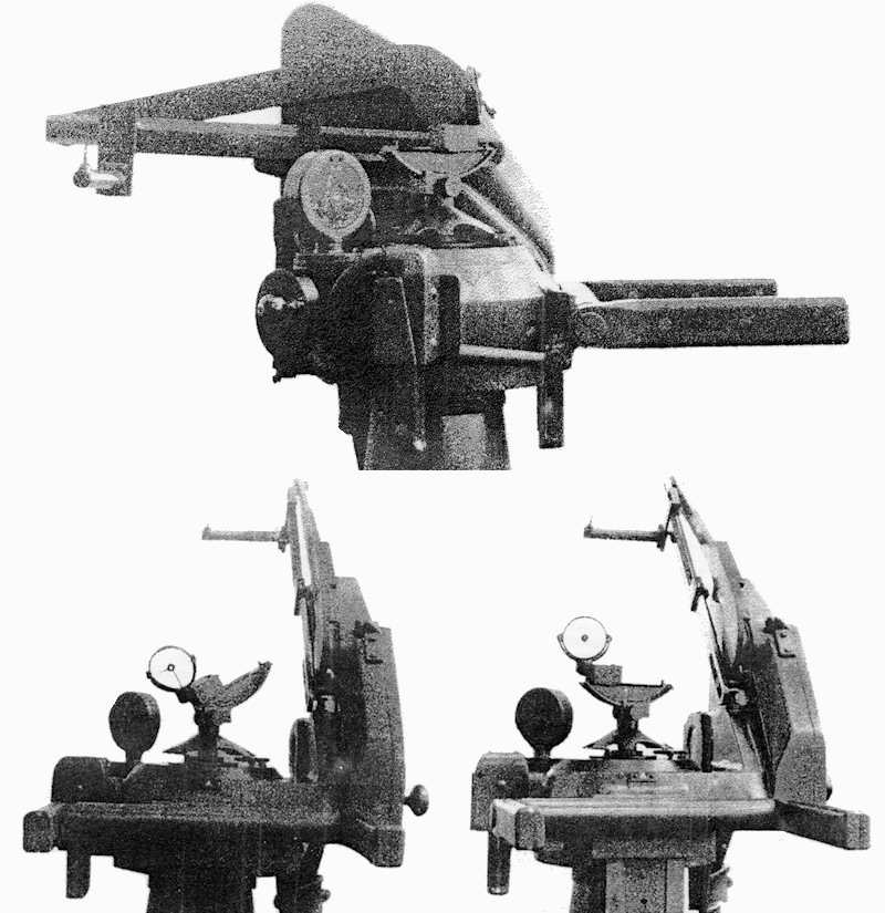
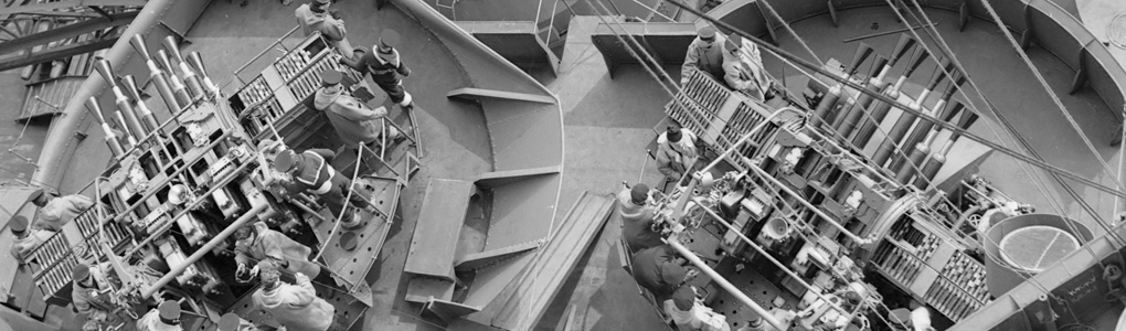
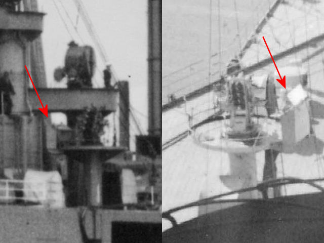
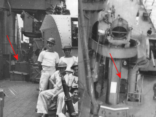
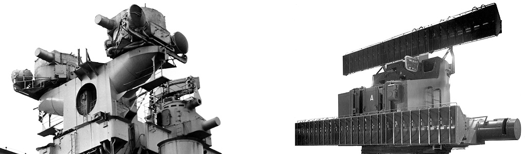
Here’s all the photographic material of the Mk I I could find. No measurements or general dimensions and no details of the lower part of the director.
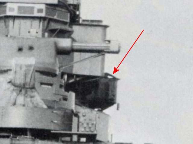
The picture above shows something that does resemble the director greatly and is so far the only picture I have of the Mk I director “in the wild”. It also allows me to estimate the general dimensions, even though the dimensions of its emplacement are estimates as well.
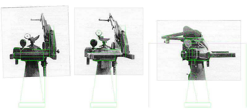
Here’s the reconstruction in Autocad. The image at right is with the estimated tub dimensions of the spotting top emplacements.
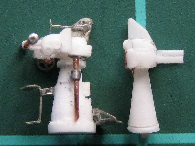
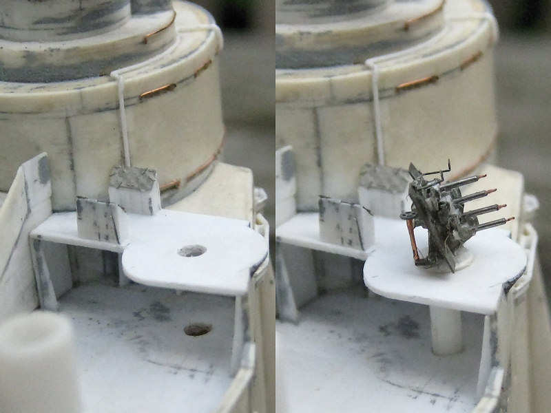
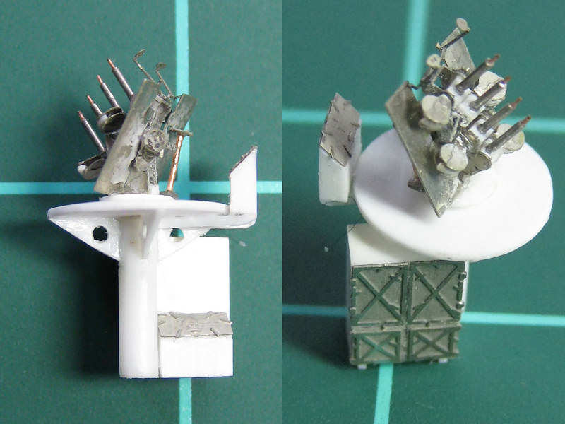
This is the model of the Mk I together with the better-documented Mk II director. It’s not really much lower, but it does have a smaller footprint. I do not know if there are chairs and platforms fitted to the pedestal, as I do not have any more information. I do know there were more chairs fitted to the Mk II so that model will be updated later when my new etch set is completed. Of course, several etched parts for the foresight bars of this Mk I director will be included.
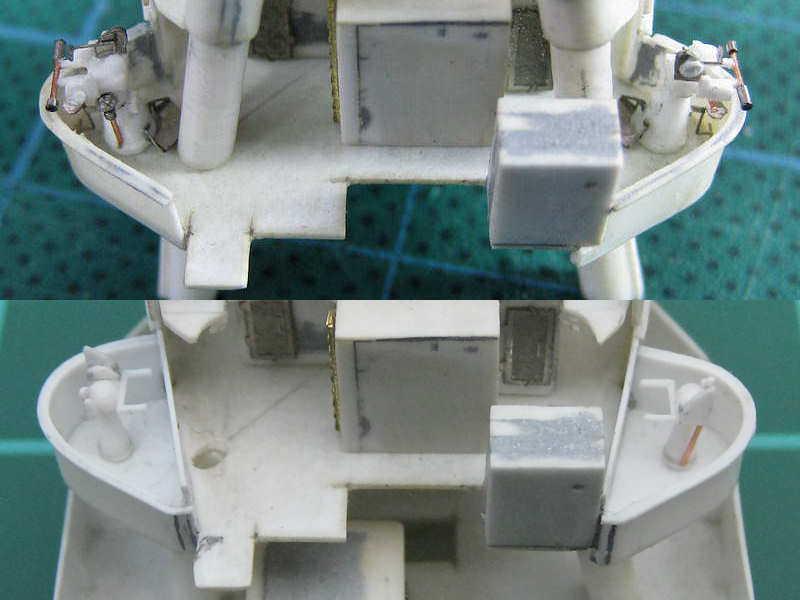
Here you can see the Mk I directors at their correct location. I copied an earlier picture with the Mk IIs. Note that the splinter shield now runs behind the directors, as is evident on photographs printed in Chesneau’s book. I changed the sponsons too: the radius of curvature is now equal to the radius of the circular emplacements on the spotting top when the directors where fitted aloft (AOTS Hood). The final locations were also fitted a bit lower than deck level to match the photographs better.
So, a lot of work and money spent on two puny directors that nobody knows what they look like… but one step closer to getting this model more correct than any other. I guess that matters.