
The models for HMS Hood’s funnels were already completed a few years ago and were of the few remaining parts of the first generation. The walkway at the center of the funnel was solid styrene, not a nice new etched walkway and the railings weren’t done so nice. So, I decided to have new parts for the funnel in the etch set for the walkway and the one-bar railing and start all over. Little did I know that these were the parts with the highest failure rate of any sub project I did so far.
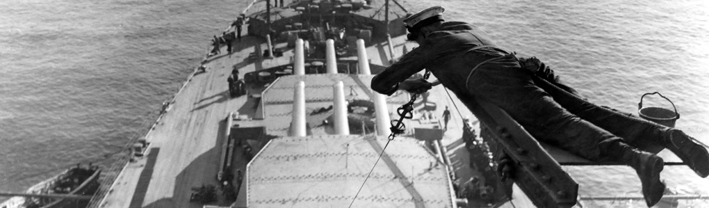
This is the only one good shot (known to me) of the funnel interior, taking from high up in the bridge structure. It would have been wonderful if the sailor who took the image would have taken one of the funnel closer to the bridge so that the interior would be fully visible, because almost no other information is to be found. You have to interpret the image careful to distinguish between the railing of the walkway and the vertical and horizontal supporting bars and stays. The first thing to note is that there a walkway going around at the edge (so that the crew can deploy and fix a canvas cover) and a walkway in the ships length direction, but there is no walkway across the funnel in beam direction. Second, note that the (only) walkway across the funnel ends a bit higher at the far than the walkway around the funnel. As the funnel cage is curved, it would make sense for the across walkway to correct for this curvature and be a bit higher so the crew can pull the canvas cover over the grid. These covers are rarely used and are seen mainly when ships are being built or when mothballed
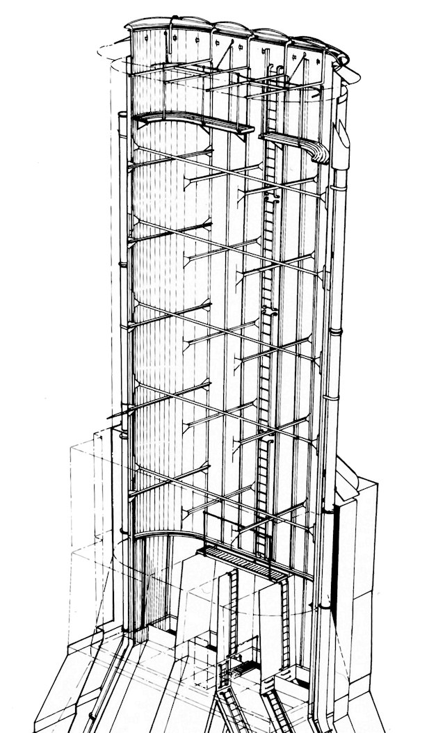
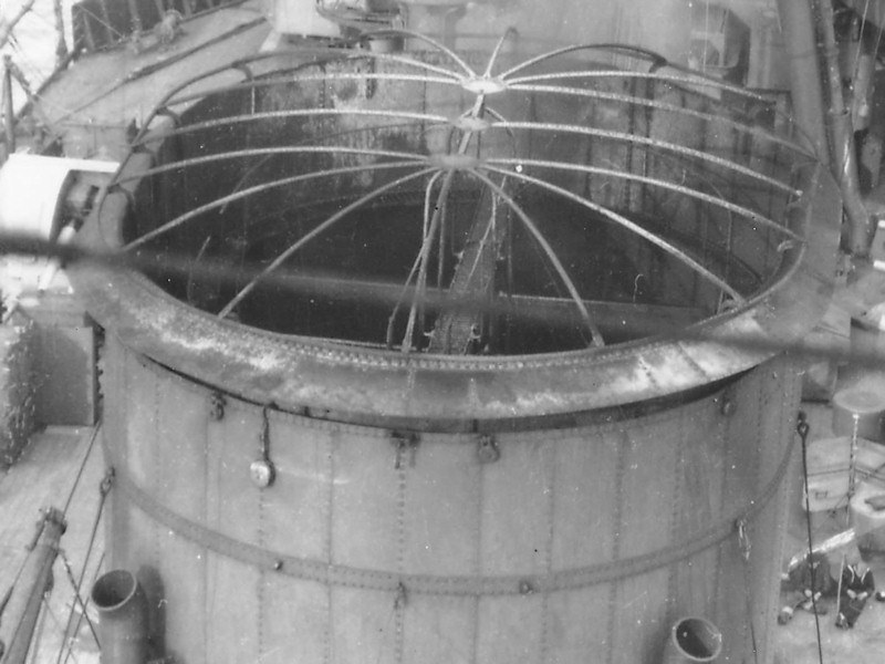
Few drawings of the funnel interiors exist at all but I managed to find two in Anatomy of the Ship (AOTS) Dreadnought and Belfast. This image is from the former source, by John Roberts. Even here it is mentioned that the exact layout is not known and is based on contemporary design. I decided to “create” HMS Hood’s funnels based on this information. You can notice a few things in this wonderful drawing. First, a ladder is seen from deep within the funnel going toward the walkway. The crew had to access the funnel from the upper deck. Now, if you look at the top image, you’ll notice that there’s an opening in the railing of the walkway. Hence, an opening for a ladder must be present for HMS Hood’s funnel as well. So, the shape of the walkway is distinctly different for the walkway as sketched by Roberts in AOTS HMS Hood.
Second, a large number of internal funnel stays are visible. The position of the stays remains unknown, except the two in the top image. Two vertical supports from the funnel cage down to the walkway seem to be at the same position. However, only two supports sound a bit low so I added two additional rows. I cheated a bit, as you cannot see them in the top image, so I decided to let those additional two stays start a row lower down. The stays end above the division plates at the bottom of the funnel. I didn’t add an etched walkway for this funnel interior, as I forgot about it and the previous version of the funnel ended one deck higher on the model so it couldn’t be placed. So, I’ve hacked that part away to show the division plates. Anyway, the design for the educated-guess funnel interior is now done.
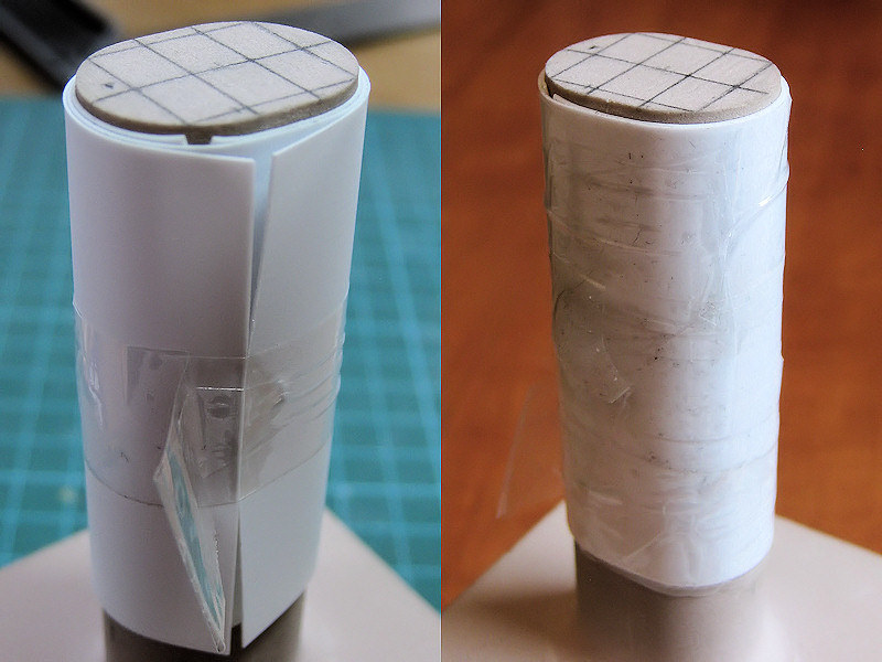
A hollow funnel is one thing, but snugly fitting the etched part is something else, so I experimented a bit. I had a mould made from the dimensions of the etched walkway and wrapped it with plastic plate and put it in the oven. I spent a lot of time playing around with the plate thickness, the dimensions to get a good part, the temperature and the heating time. I ended up at 150 degrees (C) for two and a half minutes. The result is a thin 0.25mm plate with the correct shape. A second plate was wrapped around the first one and they were glued together. I had to add a few markers so that the plates were glued in the same position when they were heated, of they might deform the funnel a bit.
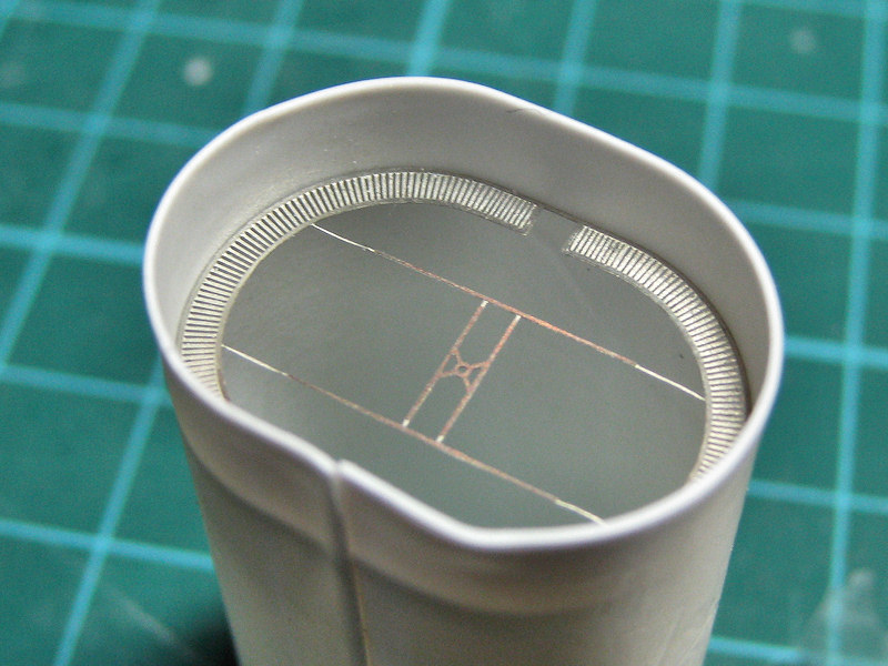
The result is a heat-treated funnel that fits the etched part like a glove! (the part in the middle is the antenna for the Type 273 radar and is not part of the funnel).

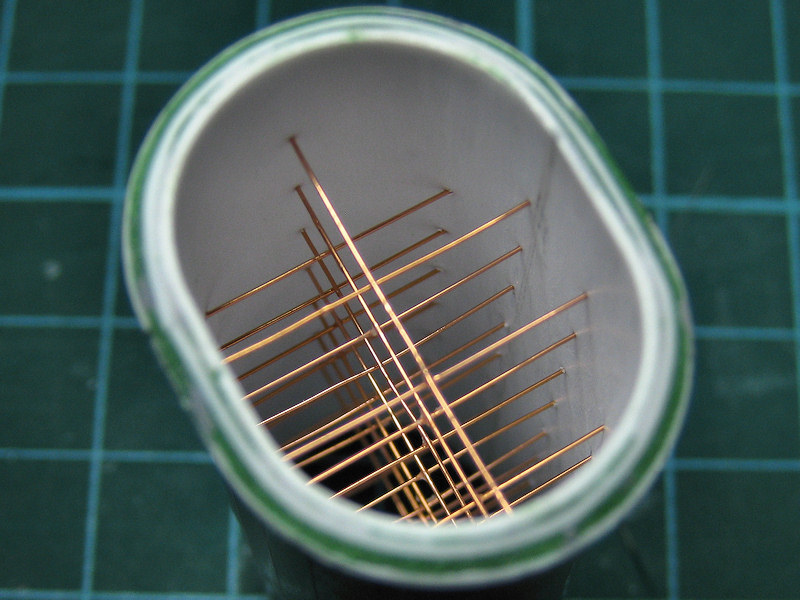
Adding the stays was the next experiment. I make a small ring from two additional layers of heat-treated plates and drilled in the funnel with a 0.2mm drill. Brass rod was inserted, glued with CA and later trimmed to size. I made several attempts, as a small misalignment of a row of holes showed up only too easily. The rod was added with the funnel on the mould to have something to hold the funnel with, lowering the mould with each successive row.
The result looks quite good, though I had to be careful not to exert too much force bending the brass rod which doesn’t bend back. Corrections can be made, but the results were not always too precise for my taste. So, for my second series (reason for doing so stated below), I tried using fishing wire. A series of channels was carved in the outer plate and the wire was weaved around the funnel. This did solve the problem of a brass wire not being able to stand tension, replaced by a wire that couldn’t take compression. So, I had to use some force pulling the wire taut, and I tore a hole through one of the funnels at the last pass (of course). Not so useful either. Still, all the channels and adding some pretension did work out quite well, so I went back to brass wire.
So I kept the idea for the channels and added some tension by pulling the wire and bending it downwards before trimming it to size. A third layer of styrene was added to bring the funnel to its required thickness before adding the exterior detail: next in line were the rivets on the outside of the funnel.
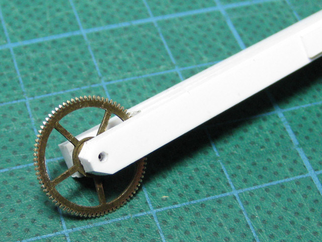
I already added some rivets to the tops of the main gun turret and decided to continue that technique here. I visited a repair shop for antique clocks and they gave me a collection of very fine gears. I made the tool you see in the picture above.
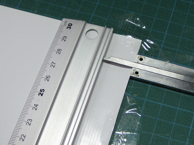
The plate width required for the funnel was first measured carefully using test plates and divided in strips. Using a table, the caliper, and a ruler, I rolled in line after line of rivet detail.

The result is a nice plate, a bit over-scale, but the effect should be worth it.
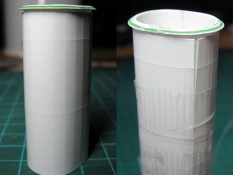
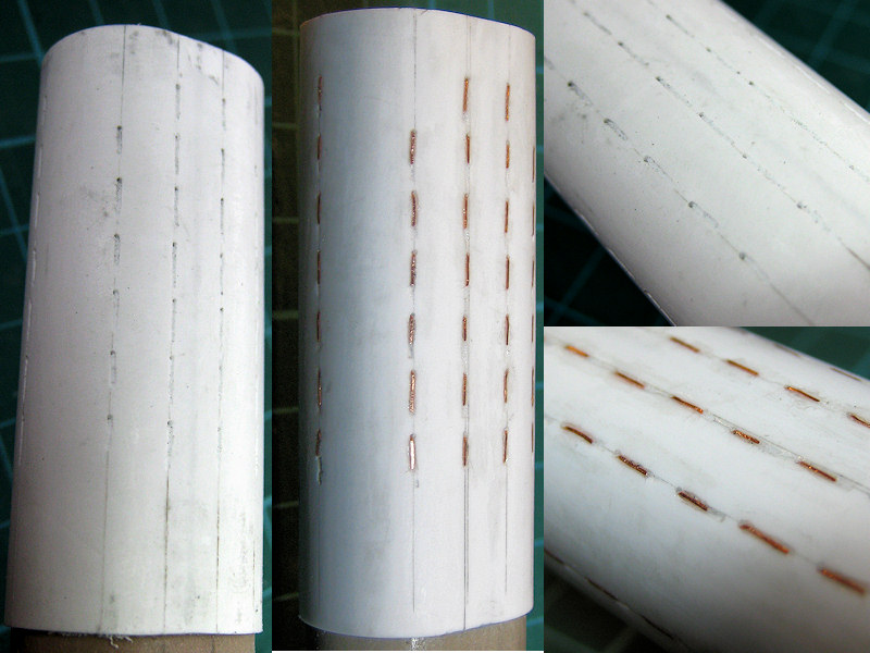
Adding the plate proved to be quite troublesome, as you cannot use normal glue as that will melt the thin plate and using superglue leaves very little room for error. Here can see the test fits of the plates (I had only half the rivets on the left funnel, so it was replaced).
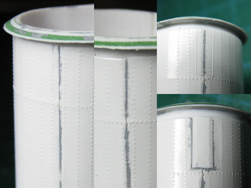
The problem with the first set of funnels was that I accidentally removed a bit of rivet detail. The split between the plate ends is cleverly hidden behind steam pipes, but still, people may want to go searching for errors for the funnels just to see if there’s a plate line and spot the ugly area. I tried to repair this part by cutting out a part of the riveted sheet and add some replacement sheet, making matters much worse! These funnels were trashed, something I learned to regret later on, as these funnels were really a lot of work.

So here are the last versions of the funnels. I didn’t manage to have the horizontal bolt lines align properly for both funnels. Gluing was quite tricky, as the plate needs to be aligned properly and the smallest deviation will show up. Work to fast and you can make an error. Work to slow and the glue may form lumps that will show up immediately and you need to carve off the plating and clean the funnel (another hour or two). The split is filled and looks reasonably fine on a close-up and it’s tricky not to damage the lines of bolts on either side of the gap. Do note that the spacing between rivet lines along the split matches the distance between other lines quite well (hurray for planning ahead). Fortunately the double steam pipes, one set per funnel both over the split, will run over the horizontal lines.
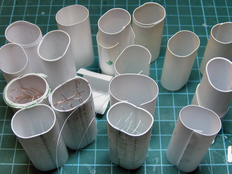
Here you can see a collection of the failures.