Category: Armament

Vickers Quad Machine Guns

HMS Hood carries four quad 0.5 inch machine guns. Rather ineffective and antiquated weapons I’d guess. I designed the etched parts a year or two back, and I forgot how I got carried away drawing these parts on a large computer screen using John Lambert’s excellent drawing. When I saw the final etching, I wondered if I hadn’t perhaps gone little too far. A test assembly didn’t really work out, some etched parts were just too small to handle. The final assembly worked out far better, although I spent as much time folding and gluing the parts as I did scraping away excess glue. Not an easy task, as this part is very weak and doesn’t tolerate much, if anything.

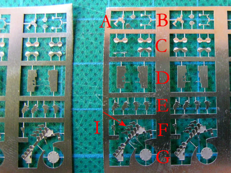
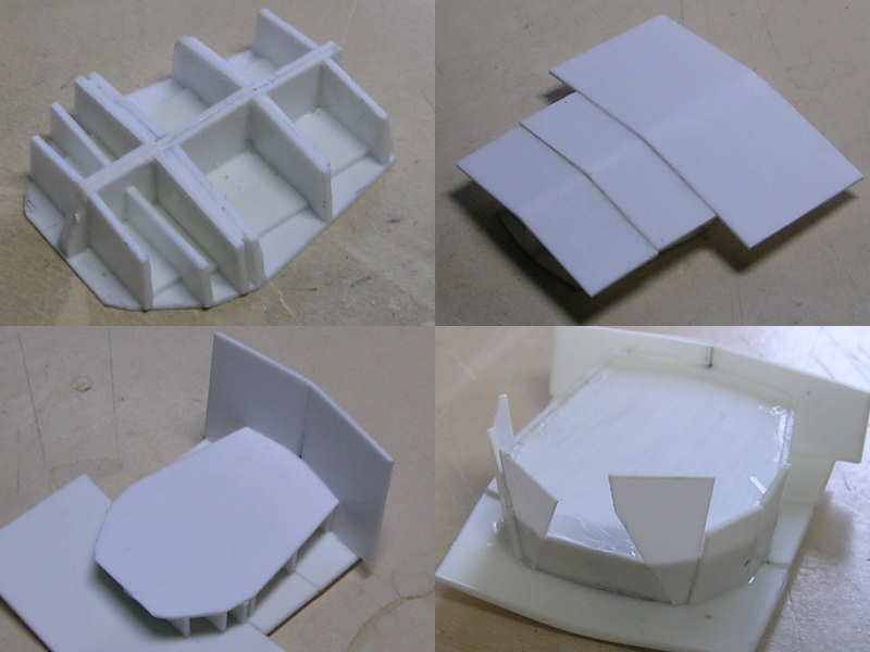
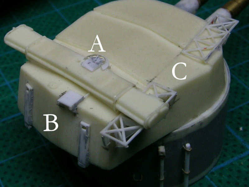
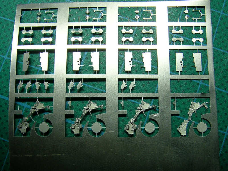
This is the original set of etched parts. Visible are the elevation gear (A), the elevation and traversing hand wheels and open sights (B), the ammunition drums (C), the bullet proof shields (D), some construction to collect or eject spent casings (E), the main part (F), the base plate (G), and some part which I forgot goes where (I). The indicated detail of F was supposed to be folded onto F, but most parts suffered some wear and broke off during folding. I added them by hand, but it was really difficult to spot the difference. In the end, I cut them all off. Unfortunately, part E was counting on the added 0.2mm thickness, as it partially overlaps parts A, so parts A were trimmed.

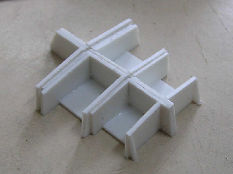
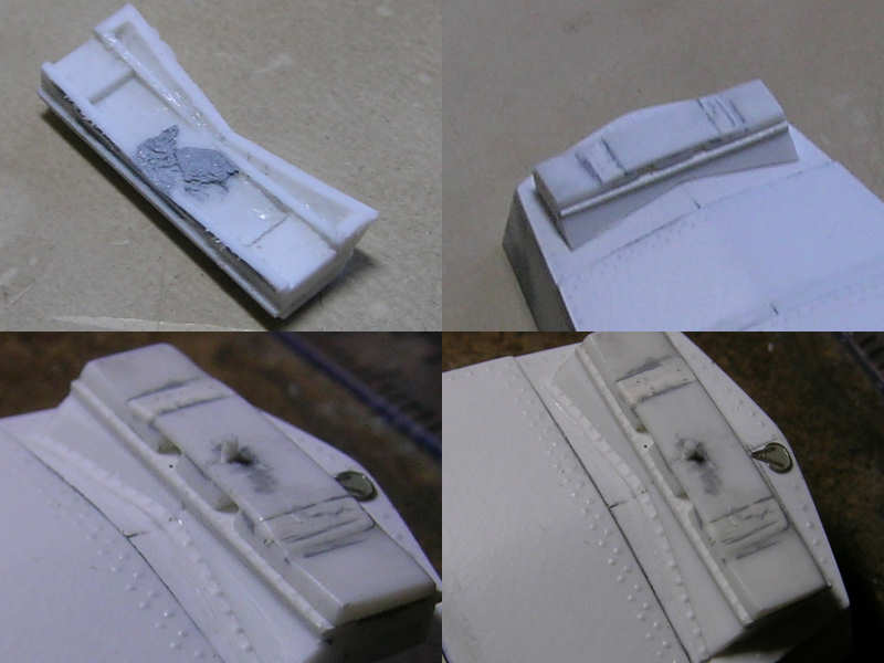
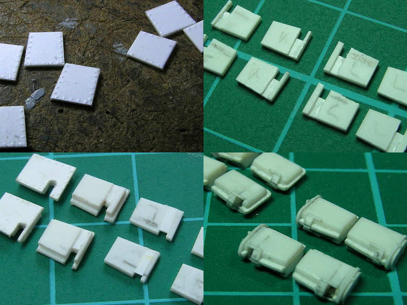
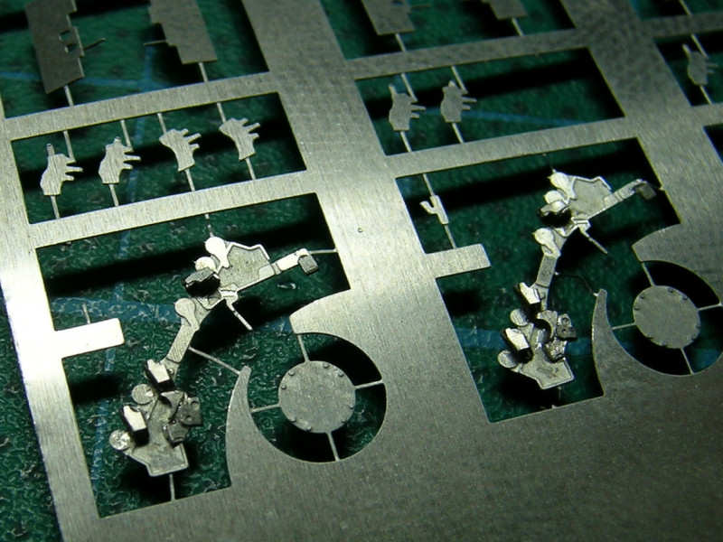
Parts E are very small, and it was impossible to keep them apart during the trial fittings. But, dry fitting went quite well, so I decided to keep the parts. Here you can see them glued onto the main body. With such small parts, you really need something to hold on to, so keeping the parts in the fret isn’t such a bad idea.

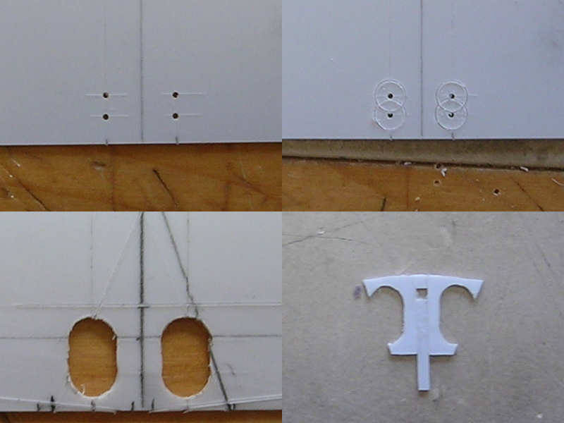
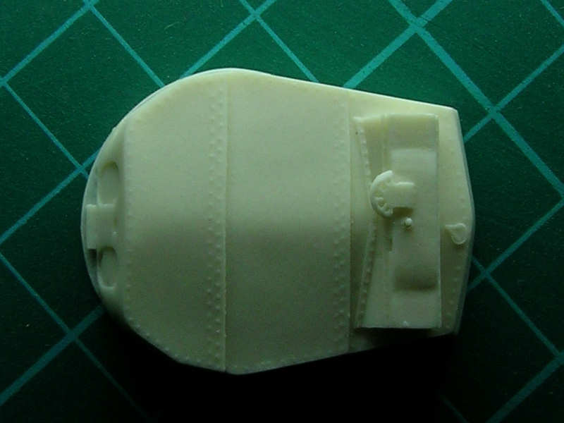
A close up with the elevation gear and spent casings ejectors (?) added. Note the detail in the main body, which will later be swamped by detail and superglue. The smallest lines are only 0.1mm thick, the thinnest allowed by etching 0.1mm thick plates.

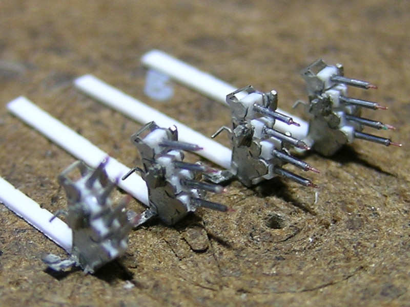
Here you can see the guns under construction. The barrels are made from Scale Caliber tubing, purchased from www.cammett.co.uk . It’s the finest tubing they sell. A small brass wire is added to be the barrel. A small styrene block with a tiny hole keeps the barrels together. The final assembly shows some sloppy gluing from gun to gun, I’m not too happy about it. But, I doubt it will be visible on the final model. I decided to have one gun at a high elevation, so people can notice it’s scratchbuilt and not some standard part.

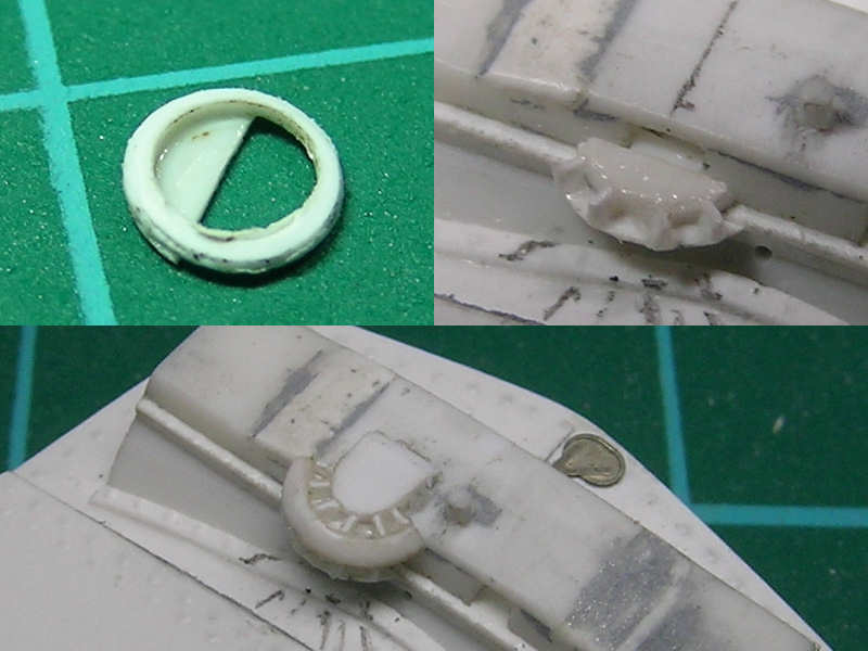
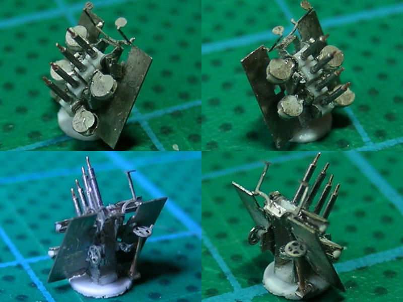
Two close-ups of the finished part. Here you can see that the ammunition drums where made with a small arc, not half a disk. The hand wheels and sights are added as well. Argh! Notice that wheel being misaligned! Hmm, the ammo druks aren’t glued properly either. Also notice that the gun is mounted on a styrene disk, aligning the part on the etched base didn’t work out at all.

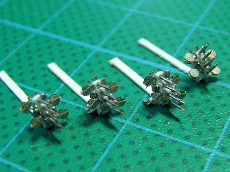
Now with the ammo cases fitted. That is really some interesting fitting and aligning… Note that the ammo cases are all aligned with the barrels, particularly well noticeable with the high-elevation variant (which was the point in the first place).

All guns on a small 1 Euro coin. It’s easy to spot small inconsistencies on the photographs, but these guns are really very small as you can see. They are about 5mm/0.2″ tall.

This was a very interesting exercise and taught me a thing or two about designing my own etched parts. The ammo drums where supposed to be glued exactly into place, but I forgot to add some markers to align them. Some parts just broke off during folding and handling (and keep on doing that). Anyway, the results look satisfying and I think this is the most detailed Vickers quad 0.5 inch in 1/350 scale. I feel comfortable tackling 30 triple 25mm guns in the future…

Main Guns

The turrets of HMS Hood are the second generation of 15″ turrets and only fitted to HMS Hood (The only ship with 15″ turrets after HMS Hood is HMS Vanguard, fitted with leftover material). The tricky part is that the bolts of the roof armor plating are very well visible while the older Mk I turrets are smooth. As I built these turrets a few years ago, I had some experience already with this difficult detail. So, when White Ensign Models asked me to build a set of replacement turrets for Trumpeter’s kit, I thought it would be a great idea.

The turret doesn’t have a 90-degree angle anywhere, only a nice flat bottom to work from. I started by drawing it out.

First, when you draw out a part and it has a few odd angles, it is worthwhile to draw a few additional lines as a framework. I drew a centerline and two parallel lines. Note that I draw the angled outlines of the turret much longer than necessary. You can use the intersection with the centerline and the parallel lines. I mirror these points on the opposite side for the other line and use these points for the other angled line. This makes cut (symmetric) lines at an angle much more accurate. It does depend a bit on how well you draw the first line, but on a large scale drawing you can repeat the exercise for measuring as well: extend an angled line and determine a few intersection points. Draw these on the styrene.

The backbone of the turret was added next. The roof of the turret consists on three large overlapping armor plates. The two forward plates are at a slight angle. As I intend to use 0.75mm plating, all dimensions are minus the plate thickness. Next to the backbones are the transverse supports cut to a 7-degree angle. Some of these plates double as a support for the side walls, but several additional side plating supports were added as well.

With all the supports in place, the roof plates can be added. These can all be trimmed to size later, after the sides are placed. The roof plates and turret rear plate are way oversize.

The front of the turret is a bit more tricky, as there are three viewing ports and I also wanted the outline of the barrel opening present. I’m not sure if Trumpeters parts will fit exactly, but I rather use the correct curvature of the turret than adapting the turret to a poor part. The shape was slightly lost with sanding…. I do hope it fits… Here you can see how I constructed the front of the turret.

The roof itself is a bit of a nightmare. I need to have the bolts well visible, but gluing them one by one didn’t really appeal to me. I used a 0.13mm Evergeen plate, the thinnest I could find, and built a few templates with the exact shape of the turret roof. With some trial and error, I managed to draw a suitable bolt line. Next, -here comes the part you’ll really like- I drilled in each individual bolt. The drill damages the 0.13mm sheet, but in a way it looks really nice from the other side. I tried this technique a few years ago and couldn’t do it, but now I seem to have a steadier hand. I filled the holes with CA to avoid damage during handling later.

Now you “only” need to glue the plate to the roof top. You can use normal glue, but that will melt the 0.13mm plate. I thought I could avoid melting this time and used plastic glue anyway. After half an hour, a small spot was plainly visible on the roof plating! I had to do the plate again! And that plate wasn’t the first version I tried either… The latest bolted rooftop was held in place with tape and I carefully added glue under the roof plate with a strip dipped in CA. This finally worked! Unfortunately I made an error when adding the second roof plate and smashed the turret to pieces when I lost my temper. This normally doesn’t happen but I wanted to have the part finished in time. Well, these things happen! Back to square one…

The rangefinder is a large cast metal object bolted in place. My previous turrets did not have these bolts but I really wanted them for the WEM set. This time I used a different technique that works quite well for straight lines of bolts. I used the gear from an antique clock, filed down the teeth and just let it roll along a ruler. Instant bolt heads! This is really a very easy thing to do and results in great subtle detail at zero cost.

The rangefinder has two openings on its front, one commanders view ports and the gun layers telescope. As this opening wasn’t documented very well and due to a lack of pics, I “forgot” to add it to my original turrets. The top of the rangefinder as a slight height increase at the center, sloping gradually at the sides. This slope was very tricky to do, as my filing skills aren’t on par with the average carpenter, so took a bit more time and effort.

A tricky part is the front of the rangefinder attaching the turret roof. It has a 45-degree slope, but connects to the roof plate that also 7-degree slope in the other direction. How to cut the V-notch out of the plate that will result in a perfect fit? Mathematics to the rescue! This angle can be easily shown to be equal to:

That just fits perfectly as you can see in the pic above. A strip with bolts was placed where it connects with the roof. I added a hatch from my own photo etch set to the rear of the turret.

The commander’s position has a wind screen. This part should be hollow, but that would be a bit tricky to cast. I started with a styrene ring filed to shape and added the supports later.

The rangefinder itself has two distinct styles, as a change was implemented somewhere in 1939. I also thought it would be neat if you could choose between open and closed viewport, so eventually I ended up making eight parts.

The top left image shows the center plate of the range finder arms with bolts in place. I made both top and bottom parts to shape and cut out the location of the viewport. I glued the bottom part first, so I could use it to file away some material from the bolted plate. A small strip is placed in the slot, giving a nice open appearance.

Here you can see the final part, fresh from the casters. Bolt detail is nicey retained and fortunately no marks or dents are present on the turret plate.

The first part to go from the resin copies is the wind shield, which is replaced (A). Now it’s actuall a wind shield kept in place by four supports. It was made by gluing 36 degree arcs and 2mm strip angled 45 degrees at the end to a strip. The shield itself is a ring cut to size. Vents are added to the rear of the turret, including a small platform (B). A small walkway is present to gain access from the aftermost twin 4″ gun position to the turret roof. At (C) the abandoned attempts of mounting an aircraft launching installation on ‘X’-turret. This frame initially consisted of 8 squares with a cross bond, but the two center squares were later removed. The remnants of the frame were present the rest of HMS Hood’s carreer. I haven’t seen this particular detail correct on any model.

Copyright © 2024 On The Slipway

Theme by Anders NorenUp ↑