
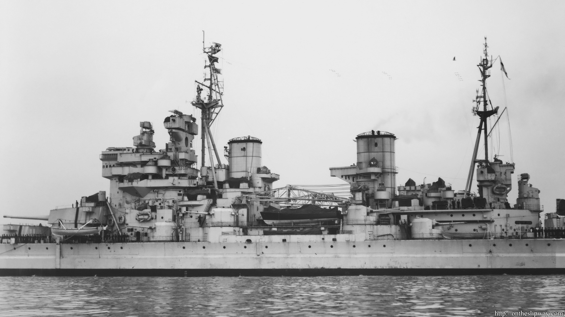
HMS Duke of York was scrapped in 1958; there are many more photographs in Ian Buxton & Ian Johnston’s Battleship Duke of York; An anatomy from building to breaking, Seaforth Publishing, 2021.
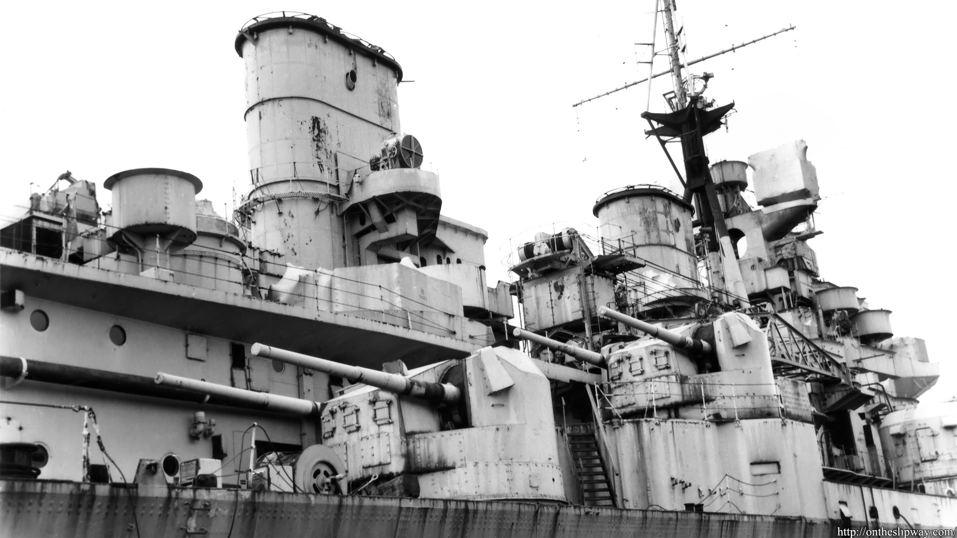
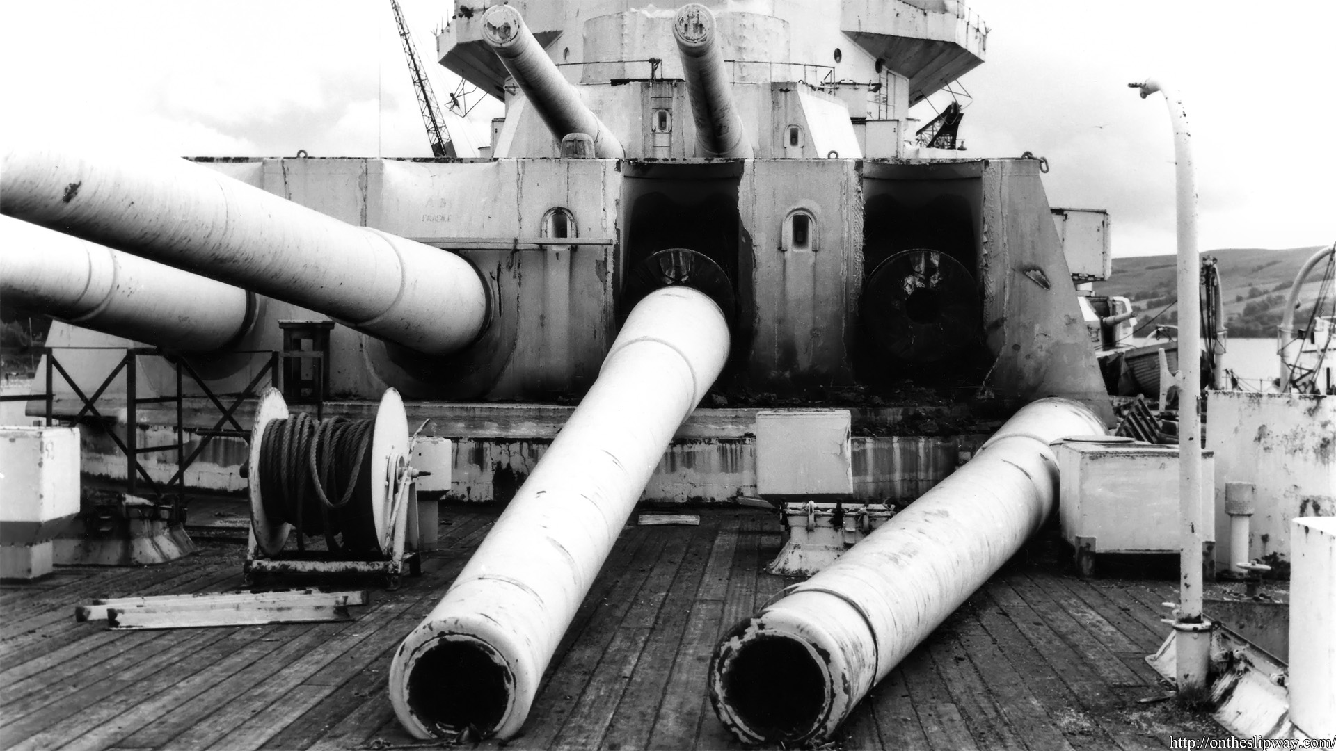
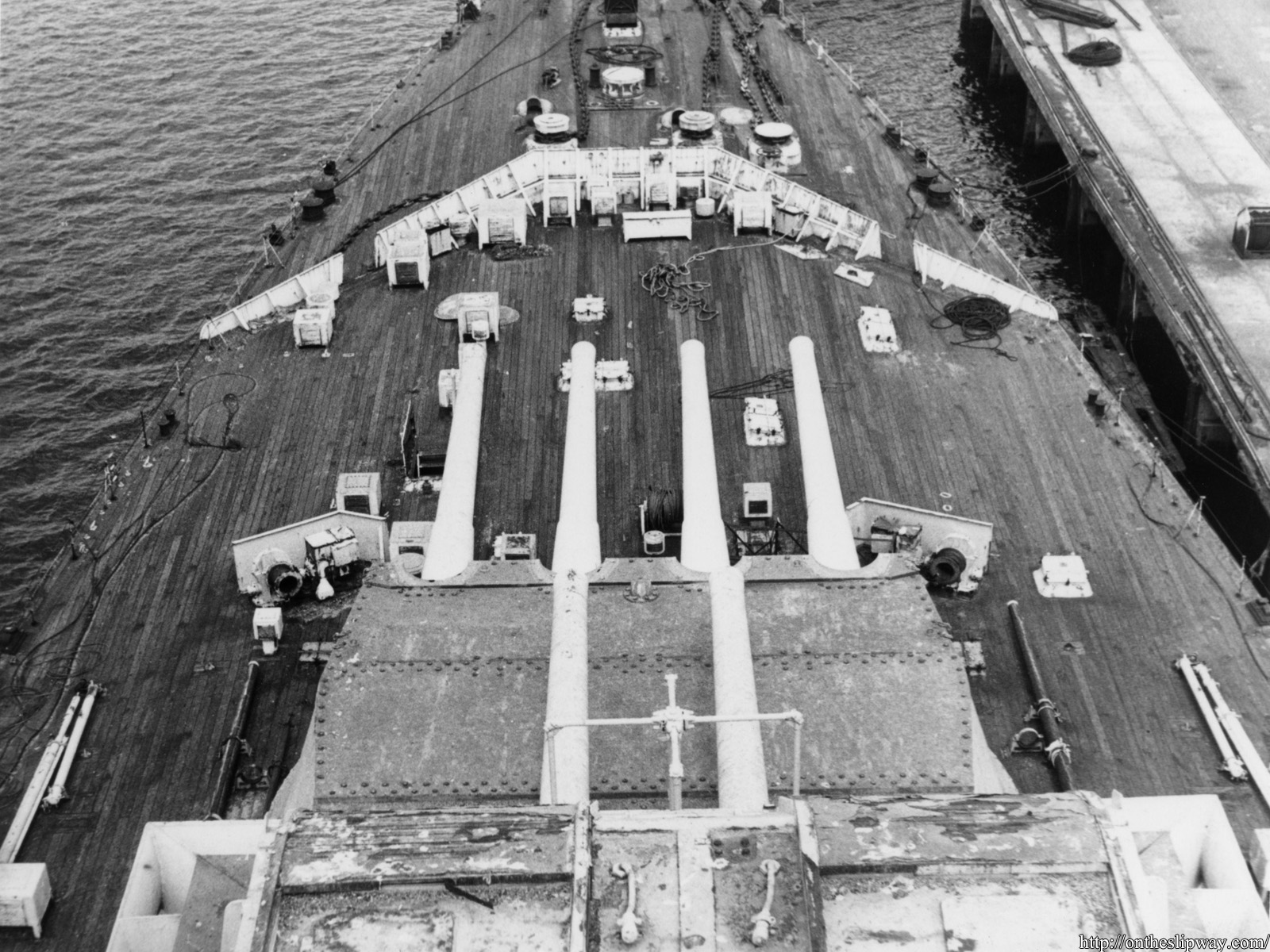
HMS Duke of York was scrapped in 1958; there are many more photographs in Ian Buxton & Ian Johnston’s Battleship Duke of York; An anatomy from building to breaking, Seaforth Publishing, 2021.
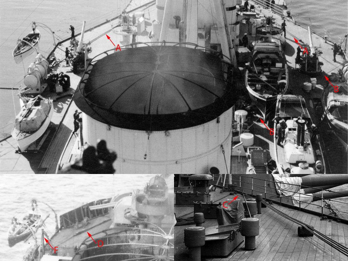
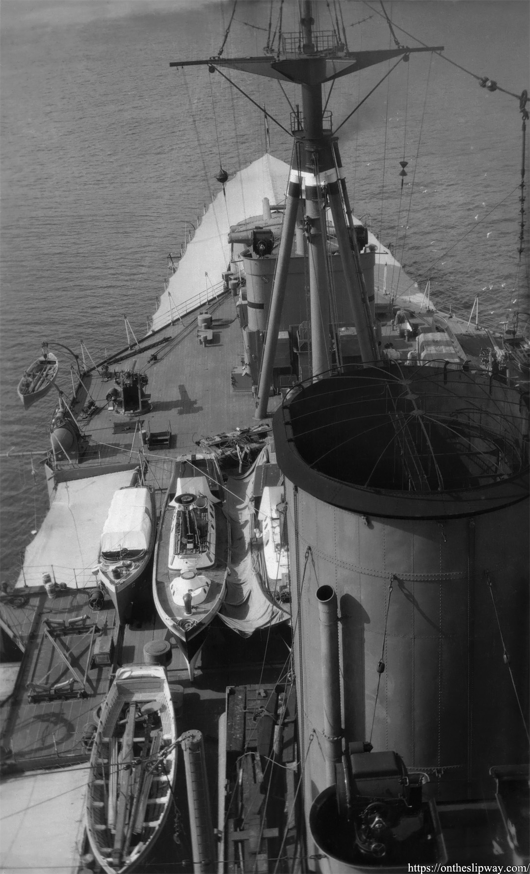
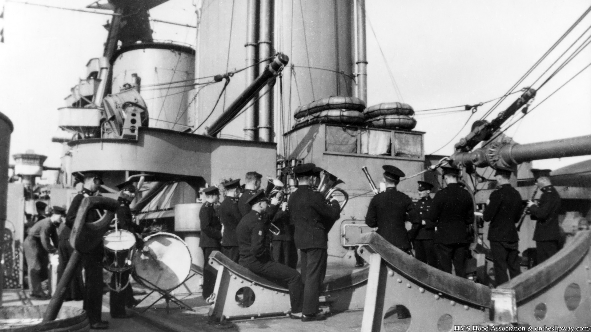
In Hood’s 1939 refit two 27ft whaler positions were added to the aft of the boat deck, replacing the cutters. I noticed there are a few ropes running from the end of the boat deck towards the davits (A); these ropes remained visible until the end of Hood’s career (D) when a small stump mast appeared as well (F). Looking closely at images of the boat deck I also found that a rope was running from the whaler position back to the derrick of the main mast (B); I could not find a good picture showing if it was the same rope as at (A). A system of two blocks was placed on the aft of the boat deck and the system was tied up somewhere out of sight between the skylights (C).
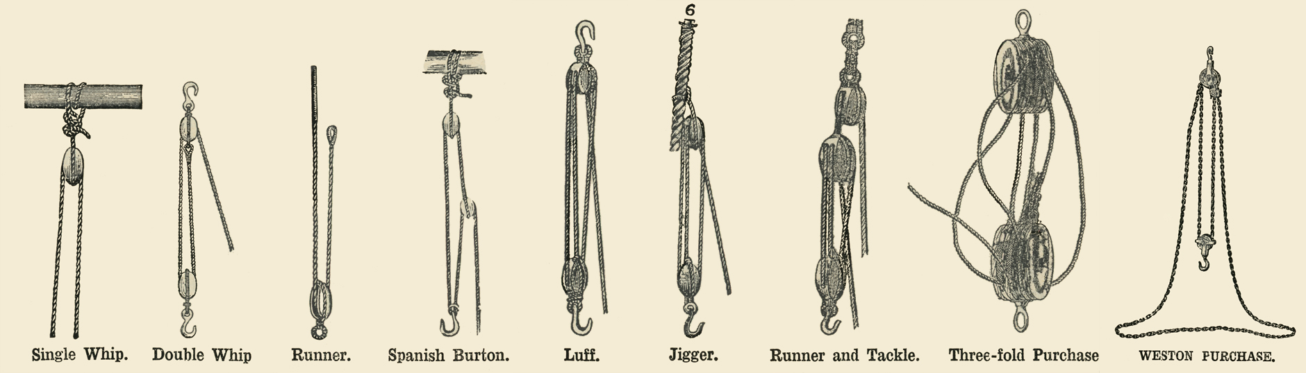
While scanning my trusty McDermaid & Manual of Seamanship I found the above images in the latter with a few examples of block variations (there are others, see https://www.hnsa.org/manuals-documents/age-of-sail/textbook-of-seamanship/tackles/). It appears when a rope goes back and forth between two blocks it’s called a purchase when that number is even and a luff when that number is odd. So that would mean in the image above our mystery cable is a luff plus a separate block running the rope towards the skylights (I wonder how long it will take a modeller of a man-o-war to master instantly naming a hoisting system correctly).
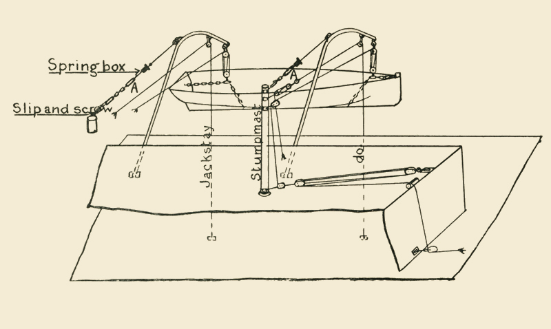
Stump masts, ropes, blocks and pulleys are not uncommon near davits as this sketch shows, throwing me further off track of the purpose of the boat deck luff. But, if you want to lower a boat then one might think that the block should be much farther away from the davits or you don’t have enough rope left; the luff aboard HMS Hood is meant to hoist something in.
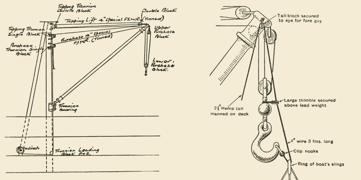
The drawings of the main mast do not show any other lines other than the lift & purchase lines plus a thrice line—an additional line when hoisting a boat in that is used to pull the ring of the boat’s sling over the hook—- but that is not a line that would require a system of blocks. Note that the cabling layout for the hook is called a (single?) purchase and not a(n inverted) double whip.
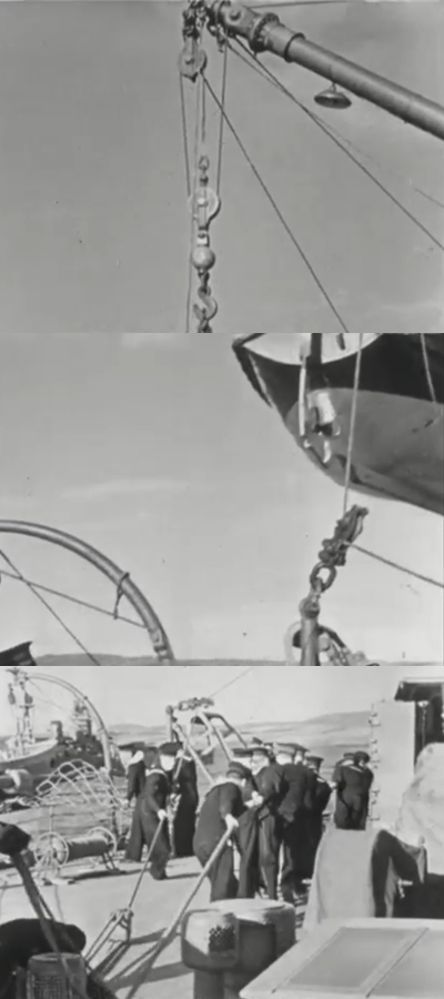
I later found the rope in action in this clip where the crew is lowering a boat; this rope is not meant to do any hoisting itself and appears to be merely a side guy to control the lateral movement of the main derrick. I’m now fairly certain that in the top images ropes A and B are the same.
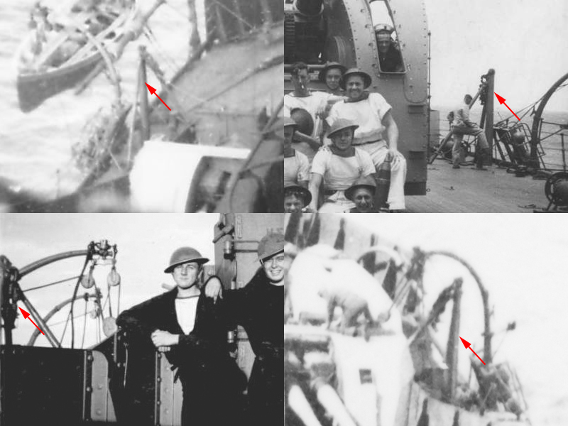
That leaves the stump mast; I think it was added to clear the 4″ turret when working the derrick and is not related to the davits at all. I estimated its height at 8 feet based on railing height and a side view showing the top of the mast.
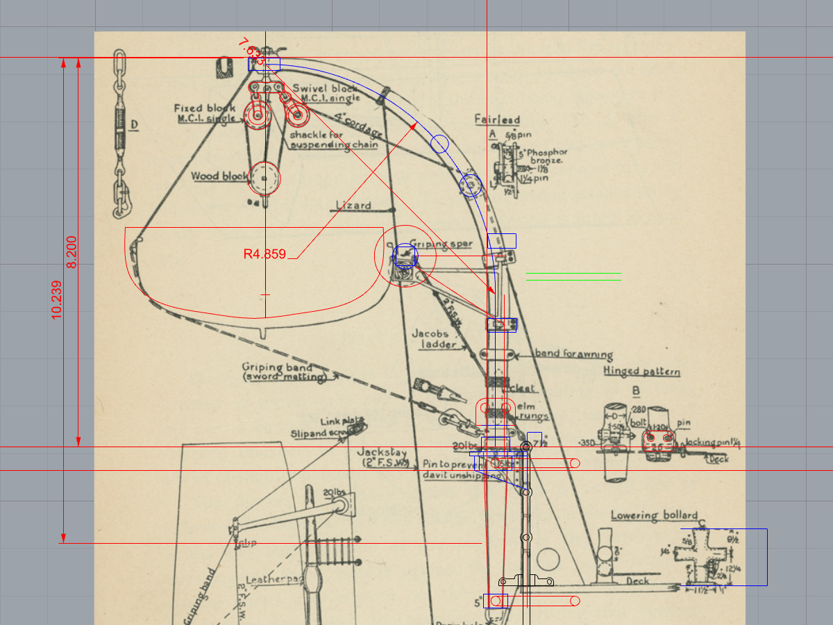
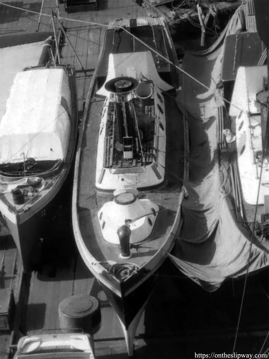
This is a small image from McDermaid showing the davits for a cutter; it has a staghorn bollard including measurements for scale. This drawing does not match the dimensions of the davits aboard HMS Hood but with a few pics I made an estimate.
The davits were made from 0.5mm brass rod with both ends tapered to 0.3mm. The pairs of holes were drilled in as explained in this post. Two davits were pairwise bent into the right position and then angled inward by about 12 degrees. Small 0.3mm rings from a 0.7mm tube with 0.2mm holes were soldered to the davits (bottom left); next two small etched parts and the rest of the tubes were added. After a few hours the davits were complete.
The griping spar was next; I didn’t file the ends square but flattened them in the vice. Two small 0.2mm holes were drilled in where the spar will be supported. I also made two “construction sites” from MDF with four small 0.4mm tubes that were added to the model as well. The davits and spars fit really well on this temporary position. The spar isn’t soldered into place yet, two cushions need to be added that I’ll make from magic sculpt pressed gently into a whaler model for a good fit, but these small models needed to be made first.
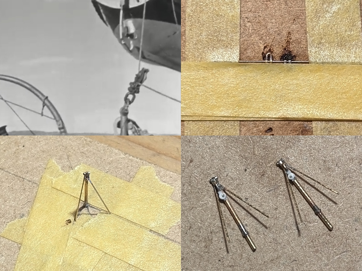
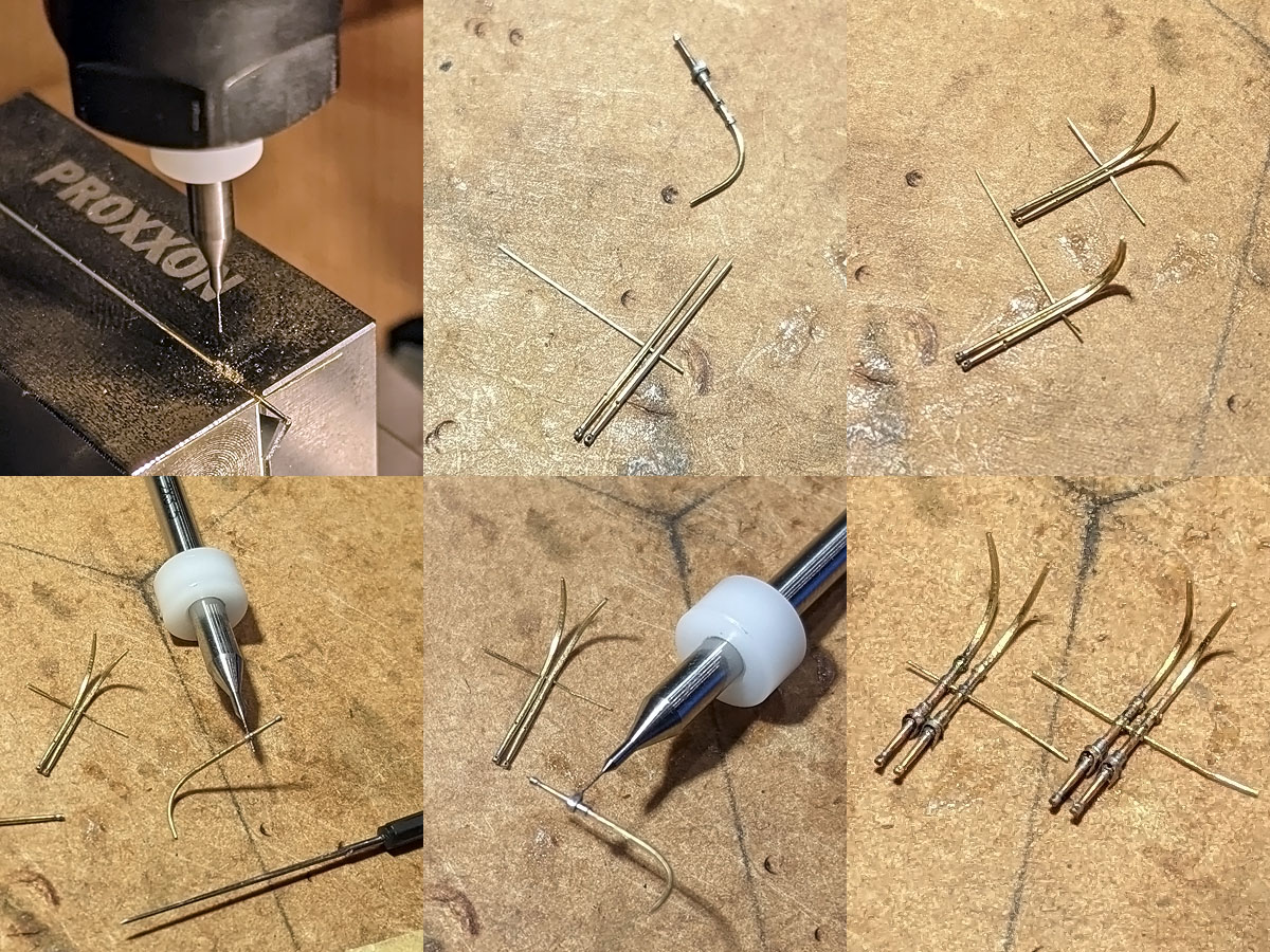
The stump mast image top left shows a single lug, a studless shackle and a pulley. The lugs % shackles were made using the same methods as detailed in the post /Ground Tackle part I, top-right showing two small lugs and four rings held in position using take and a 0.2mm drill (on which the solder doesn’t hold which is very convenient). The small tripod was soldered into place using a small jig made from MDF and tape. A tiny bit of reheating was enough to fix the small angled supports with a tiny bit of CA to prevent the lug and the shackle falling to pieces. The pulley was made from 0.5 and 0.7mm discs punched from 0.13mm styrene.
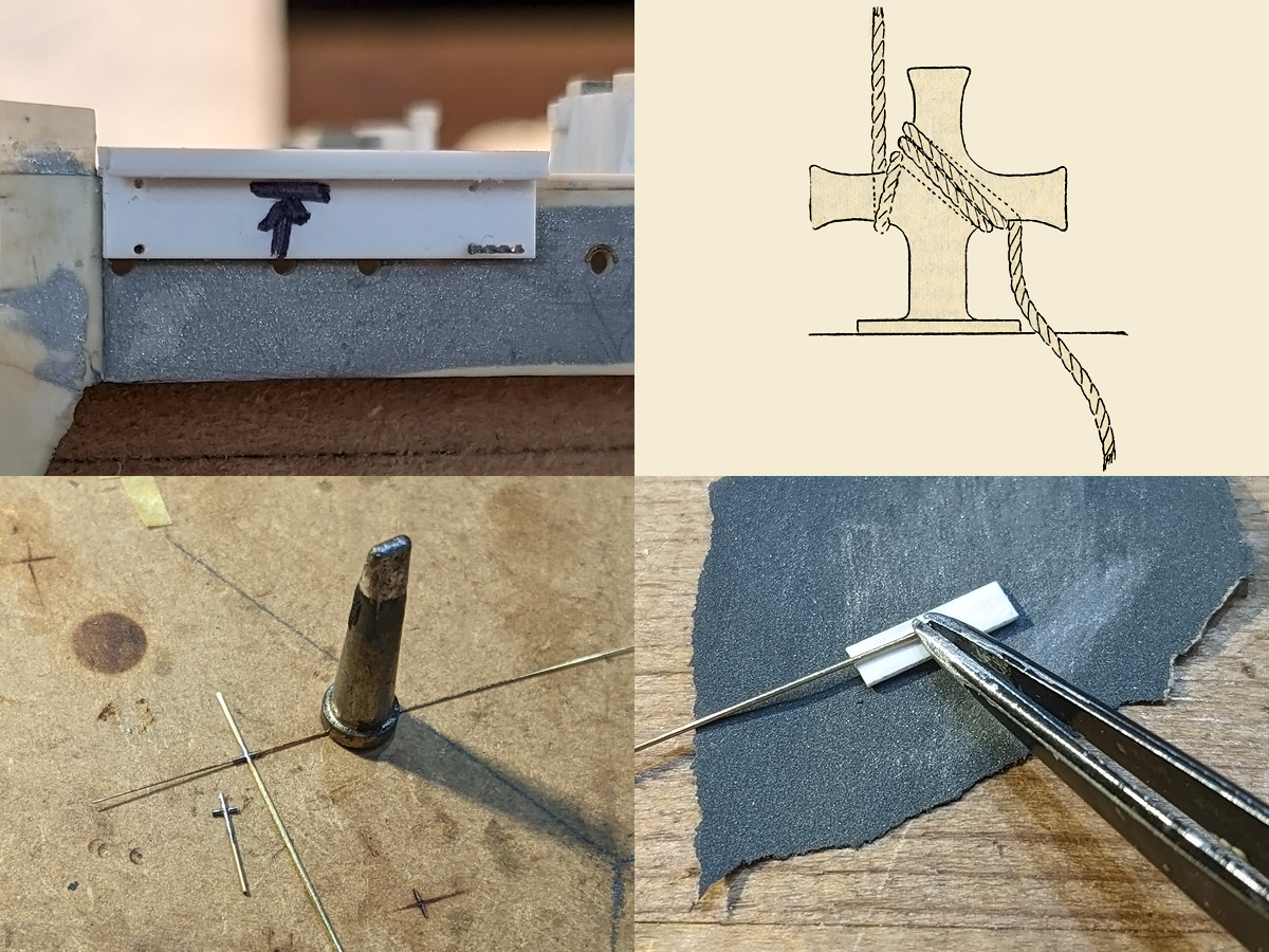
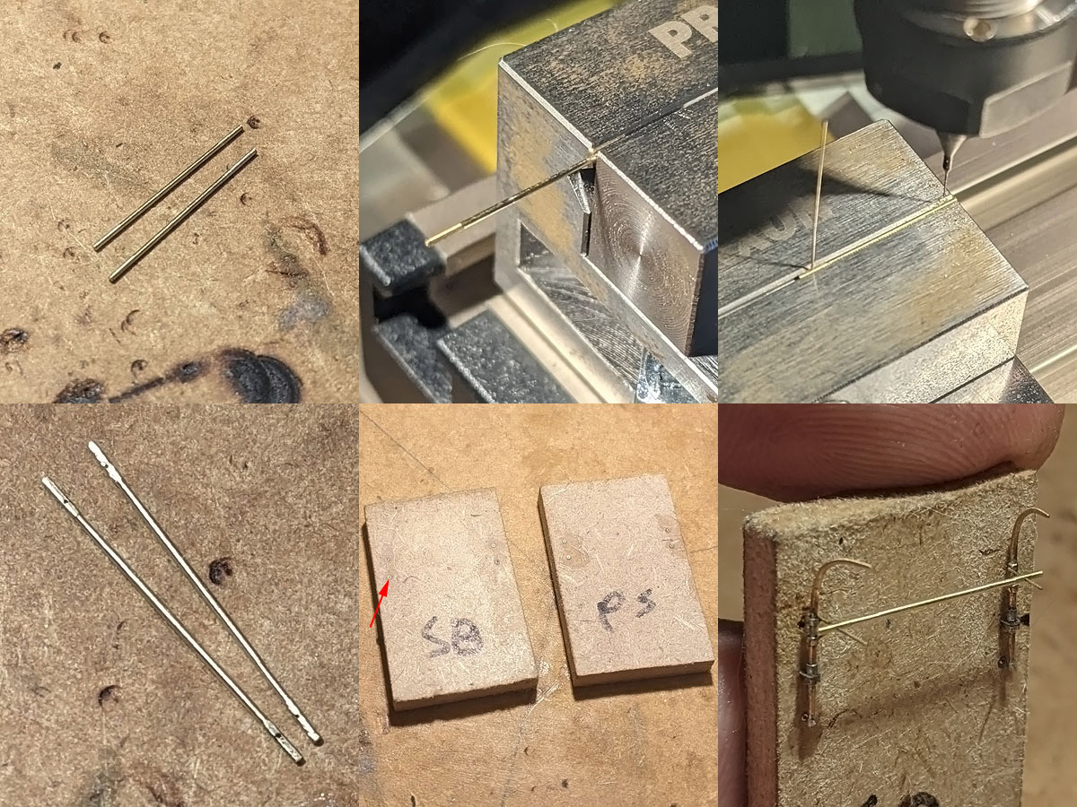
The small milling machine was used to make a jig to transfer the location of the mounting pins to the side, showing the jig pinned in place by a drill after the first hole. A few more tubes were added to the deck to receive the stump mast and four staghorn bollards. I tried making these bollards by simply soldering three rods together and then sanding them to size, but this proved to be very hard at first. Pinning down the arms with tape doesn’t work as the flux prevents the tape from sticking; using the hold & fold solves the pinning problem but that device acts as a heat sink preventing the solder from flowing (even with the largest soldering tip and at maximum burn). Drilling in the 0.4mm vertical rods and then adding a few 0.4mm tubes over a 0.2mm wire was—counter-intuitively—very easy and fast to do. These were sanded to size by sticking each end in a styrene strip of the right thickness and were then added to the boat deck model.
I had only two regrets of building HMS Hood in her April/May 1941 configuration; a bit too early for her to have one of the Admiralty first disruptive camouflage schemes and a bit too late to have a steam pinnace aboard, in my opinion the most handsome type of the ship’s boats. As described in Boats & Launches of HMS Hood, 1941, the last picket boat was not landed but still aboard when Hood was lost. I might have let useful research material slip believing it less to be relevant; I even forgot I already bought Stapleton’s book and now have two copies… (in my defence, my first copy slid behind a bookshelf out of sight).
“The term steam launch is not included. Naval Officers and ratings referred to each type of team boat, or craft, by its correct description and never used, even affectionately, the general term picket boat for every steam craft. Picket boats were either 56 feet or 50 feet in length whilst the 45 foot steam pinnaces during their existence were always referred to as pinnaces”
Stapleton, 1980
While Stapleton is quite clear in the term picket, official drawings and documents refer to a 50ft Steam Pinnace; all steam pickets are pinnaces but not all pinnaces are pickets.
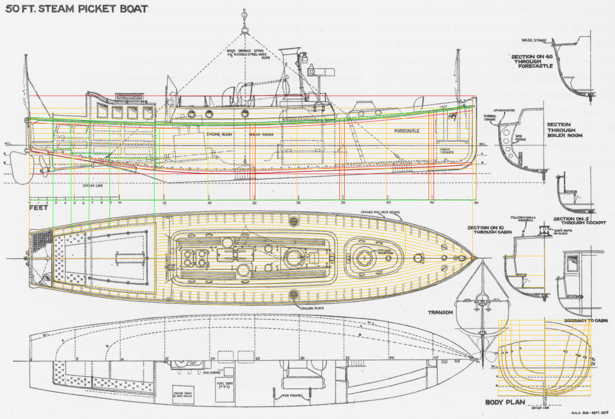
Fortunately, there is a good copy of a plan of the picket in the book on Norman Ough here loaded as a background to Rhino with various notes and lines to make the model. While going over the drawing and photographs I started to notice minor differences between the various pickets.
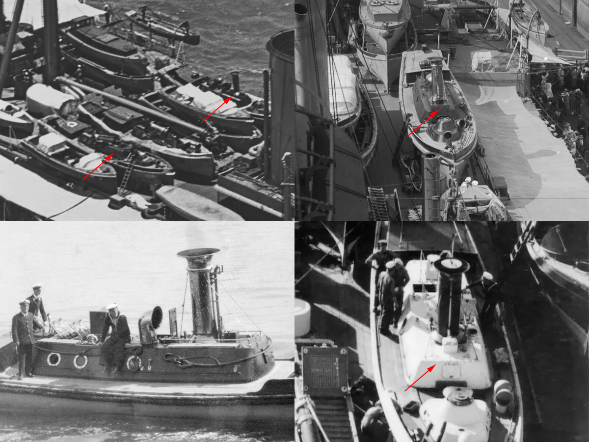
The cover over the engine room is either a low version with small ‘plateau’ below the funnel, or, a higher flat-roofed version If you look closely to the top-left image you’ll notice that Hood appears to carry one version of each. The top-right image clearly shows the ‘stepped’ cover, while the bottom images clearly show the flat-roofed version that remained present until 1941. The layout for hatches and cowlings and so on of the Ough drawing cannot be used, including the coaling chutes on deck as Hood’s pinnaces were oil-fired.
The cabin of Steam Pinnace 199 does not show characteristic S-shape; this cabin was taken from pinnace 224 from HMS Inflexible that carried 2 50ft pickets. Images of Inflexible do not show the typical 50ft pickets (with one craft not a 50ft picket at all); while her sister ship New Zealand (bottom right) does. The cabin of pinnace 199 is filed under “mysterious” and will be ignored.

Meanwhile, variations of the default cabin are found as well with HMS Rodney’s picket (top left) showing a rectangular seating area aft while nearly all other pickets show this area following the lines tapering aft (as does Hood’s picket).
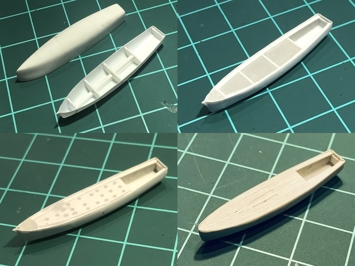
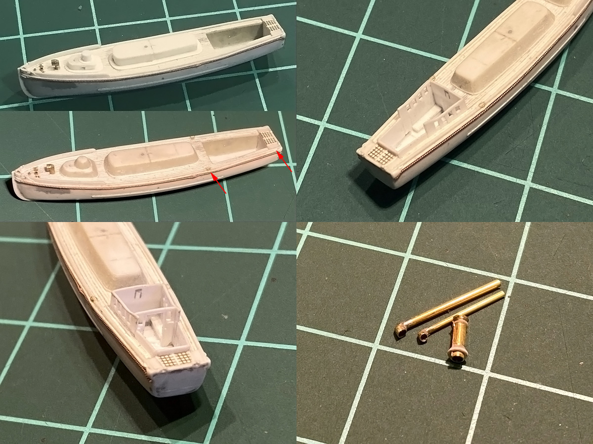
A small hull was vacuum formed from flimsy 0.25mm plate using a small plug made from Evergreen strip based on the lines from Ough. The hull was not immediately cut to size but first fitted with a few ‘bulkheads’ and filled with magic sculpt. Two layers followed, the last one the individual planks as laid on pinnace 199 with a small centreline king plank and the rest of the planks following the margin plank (except at the bow where the planks are cut off). No nibbing is visible at either the margin or king plank. The strips were made from Wave 0.2mm styrene cut to 0.25mm strips. It would be really useful if you could just buy strips and rods at smaller dimensions as I need these so often. The trick is to glue the strips almost together without fusing the gap between them.
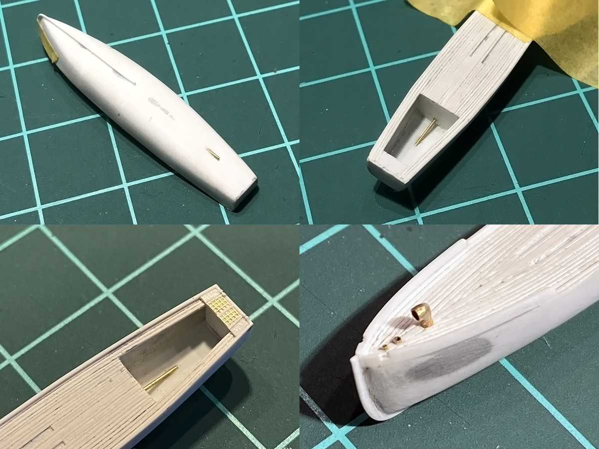
The stem strip running over the bow was first bent, taped on a small plate and boiled a bit to maintain the curve; the keel is a separate strip sanded to size. A small stern tube was added from from Albion Alloy’s 0.4mm tube; I let it run into the cabin to help alignment. The wooden grating on the aft deck is the finest mesh I could find but this mesh not fine enough and does not match the lattice outline well. On the foredeck three tubes were added for the flag post, a pipe to the chain locker and a small vent. I was worried a bit about making this complex shape. I started with a 1.0mm tube, added a 0.7mm hole/tube and soldered them together. After filing them to size with a bit of magic sculpt to round off the top the part turned out really well.
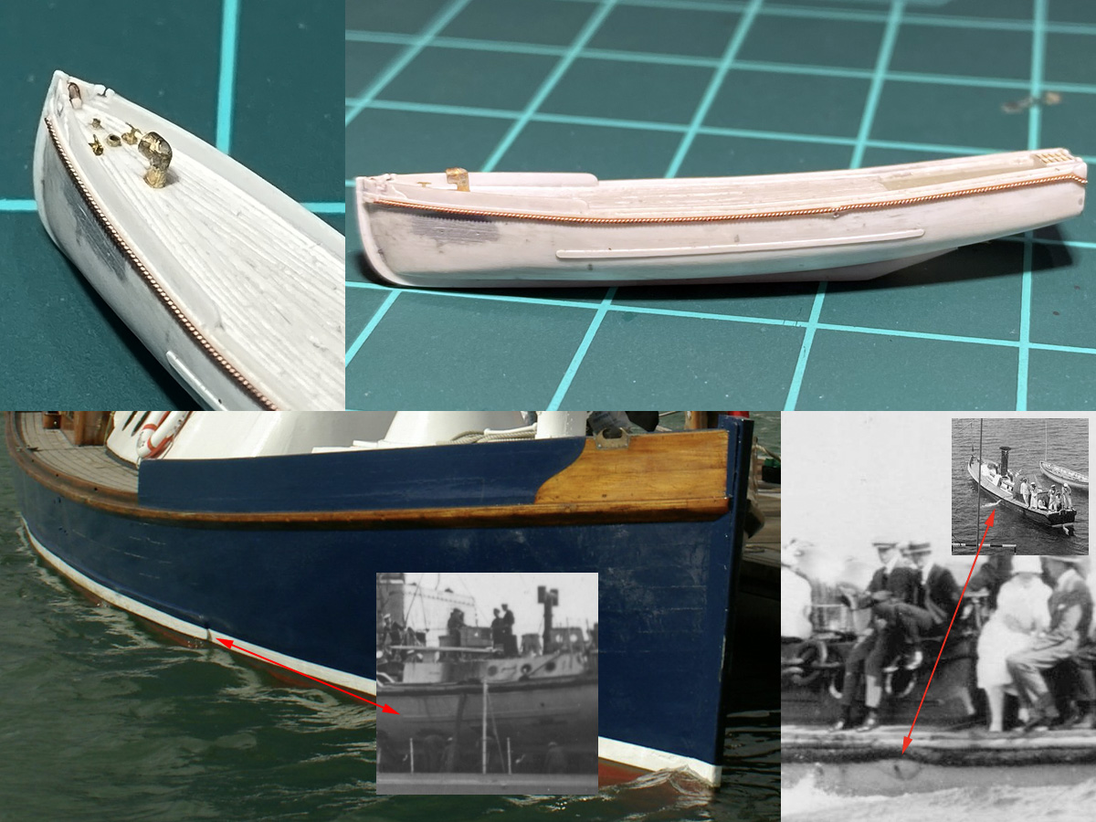
The bow received a bit more detail above the rubbing strake (or rubber) near the stem against the wash strake; this small area was often left unpainted and polished. The fairleads were another experiment using a small 0.2mm milling bit; I started by milling a small ‘T’ in a wide strip and then milled away the sides. Each fairlead has a small asymmetry that is larger than the slack in the milling machine, but it’s so small I don’t mind. The milling was easy, I had to spend more time cleaning the part and scraping away excess styrene. The cleats are leftover PE from Hood herself for details scattered around the deck edge. A small strip is present on Pinnace 199 at the waterline; not sure if Hood’s pinnace had one but Renown’s picket did and it should come in as a very handy guide when masking the hull. A bit rope was added—made from a pair 0.15 mm brass wires twisted using the drill—running over a small bump on the post side hull, I assume some cooling water discharge.
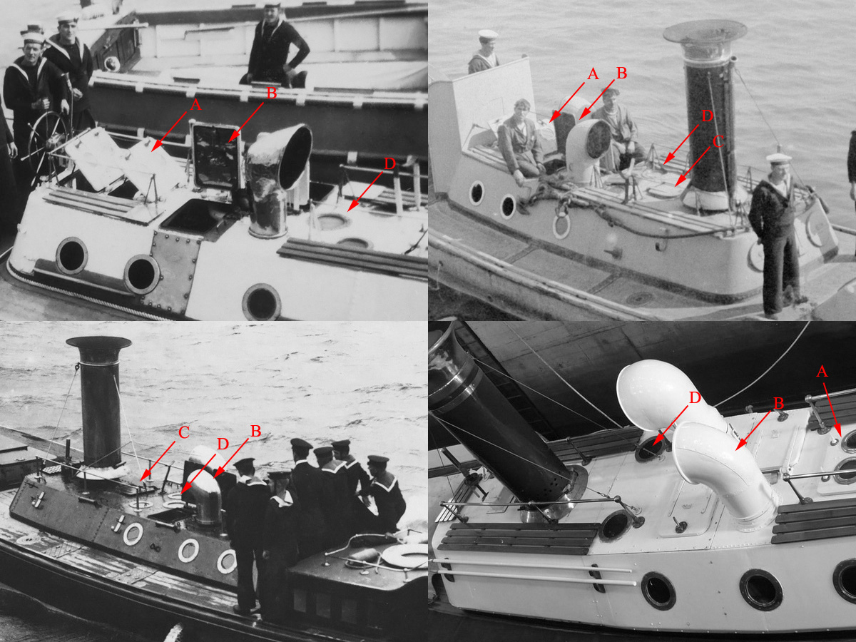
The layout of the cover over the engine room seems to be different for each picket. Ramillies’ picket (top left) has two hatches aft, opening forward. (A) Two air intakes are grouped around two hatches opening inboard (B) three scuttles are fitted in the roof between the intakes and the funnel (D). Royal Sovereign’s picket (top right) shows only two scuttles in the roof and has an additional hatch just behind the funnel (C). An unidentified picket (bottom left) also shows three scuttles in the roof and a small hatch behind the funnel; pinnace 199 (bottom right) has only two scuttles in the roof and no hatch behind the funnel.
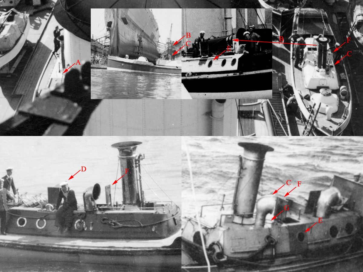
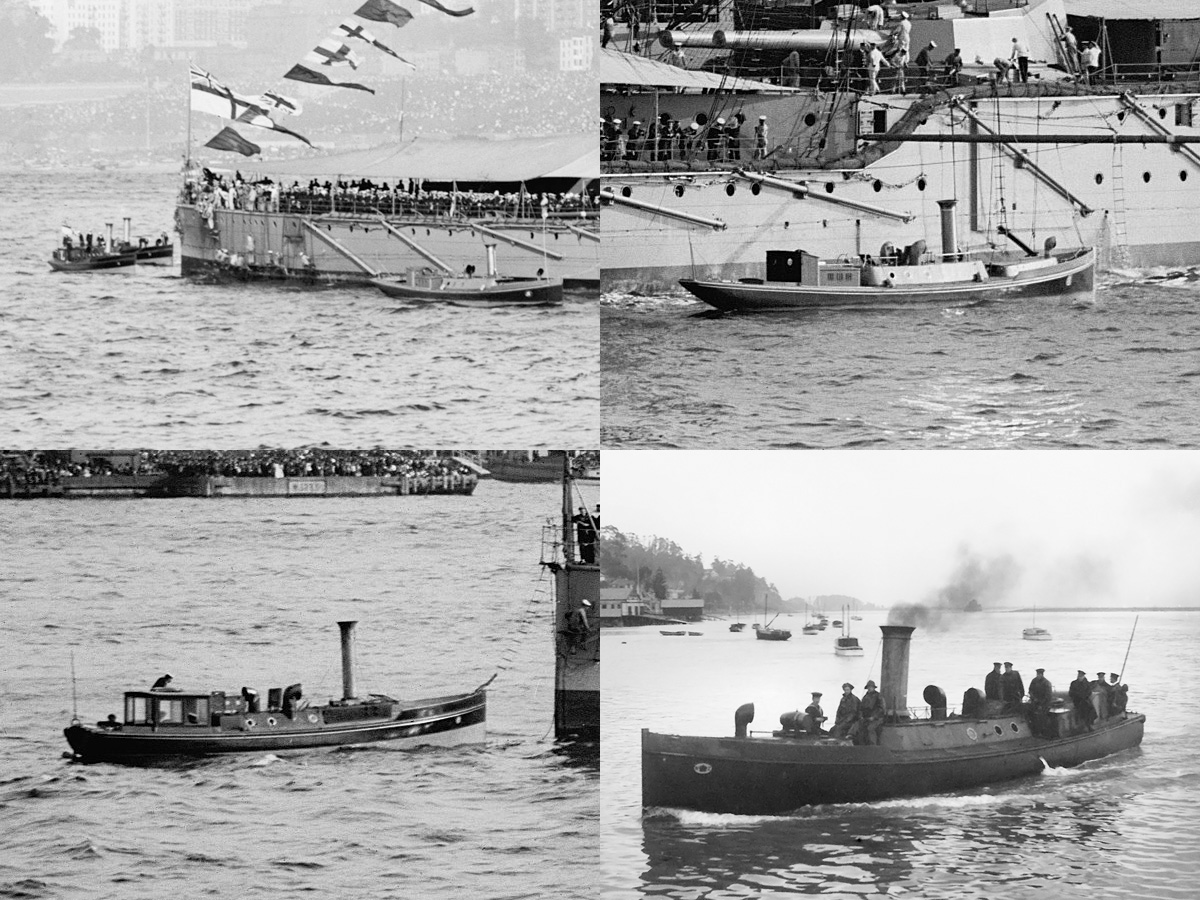
These are all pickets of Hood. A previous image showed that Hood’s pickets had a stepped and a flat-roofed cover (shown here); but on closer inspection of the top image (beneath the inserts) it seems that Hood started carrying two flat-roofed pickets (A). A few decent shots were found of the port side picket; this is picket #2 as indicated by the two brass rings around the funnel (B). This picket has the forward vent on the same side as the aft vent (C); an earlier shot (bottom left) shows the vents in other positions (plus other arrangement of steam pipes around the funnel), so definitely not the same picket #2. I noticed that the scuttles in the side of the engine room cover is not the same for the small insert and bottom right image (E) suggesting these are not the same picket either, but both have the vents on port side. So, both pickets were replaced or modified? The hatches in the roof open forward on all versions (F), in contrast to the pickets in the previous image. The bottom right also shows a pair of scuttles in the roof. I will use this layout for my model and not the one shown bottom left (edit: this image shows the same pinnace from another direction).

I found a good image on the website on the National Maritime Museum matching Hood’s picket better than the other drawings; slightly pixelated but useful enough to drawing the cover for the engine room and the base for the 3in Hotchkiss gun. Various etched parts are already drawn in. The steering wheel is connected to the rudder till via a wire runs around the outside of the hull over a number of pulleys (top view: small circles at the stern and either side of the steering position). Two small pulleys are mounted at the base of the steering assembly as well as visible-ish in the drawing; I only found a good view of that position of in a clip showing Pinnace 199 being disassembled for an overhaul (here at 4:14)
The Hotchkiss 3-pdr base and engine room cover were made from styrene sheet and then filled with Magic Sculpt. This was really tricky because of the small size of the parts glued to the model and I needed four sessions to apply these otherwise simple shapes. The arrows indicate the location of four pulleys for the steering arrangement. Top right shows the cabin under construction made from strips. The inner benches were added first as a convenient spacer at the end of the cabin. I tried spotting a door on photographs bit didn’t manage to find one, except on pinnace 199 where the doors open inwards. However, this is not possible with the S-shaped cabin shape here so I decided to keep the cabin open. The end of the cabin is again strip and both the front and aft section have a slight arc to capture the curvature of the roof. I used many ‘spacing strips’ to find the width and depth of the cabin to make all the parts fit.
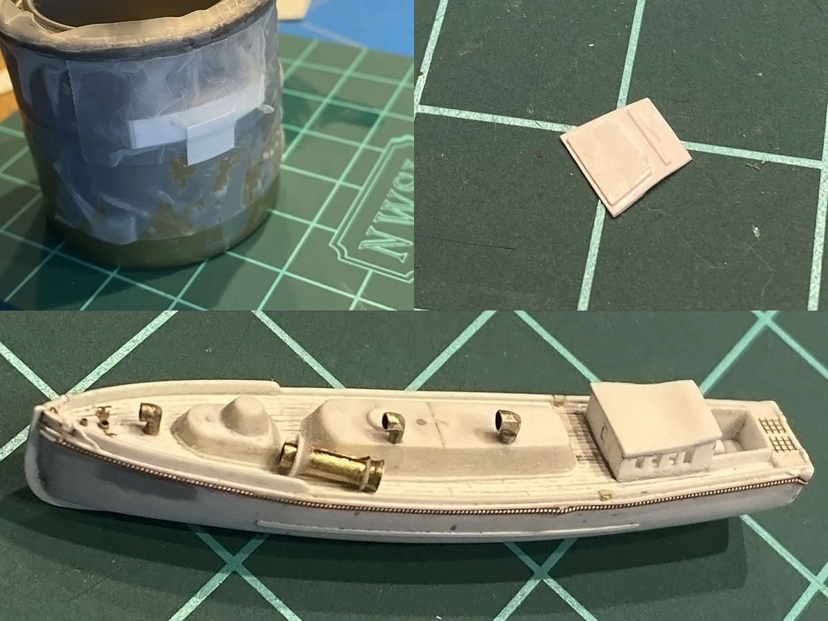
The roof has both the S-shape and a slightly curve, so I used a cheap vacuum former shown top left; simply add boiling water. A few spacer strips were added to the inside to ‘lock’ the roof into position—need to paint inside before I’ll glue the roof—and the plate could then be cut to size. Below is the model with all parts in place with ready to receive the etched parts. Two more vent cowlings were made using the same recipe as the one on the foredeck; I really like my small milling machine! The funnel was a very tricky part with the trumpet made by squeezing one end onto a dead centre on the lathe; I actually tried using a butane burner to heat the tube end, but that didn’t help one bit. In the end it was just repetition until the trumpet didn’t show any tears. The base is a bit of styrene trimmed to size on the lathe and filled with Magic Sculpt; the top ring is a bit of stretched sprue.
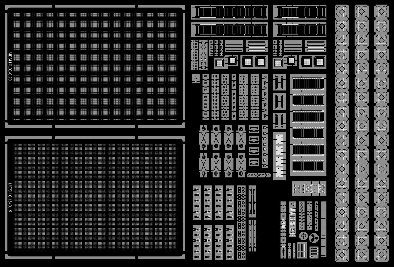
I finished a small etch set with a denser lattice and the parts for the picket bottom right. A few other parts were added as well, mainly more Denton floats (far right), missing admiralty ladders top, and re-etched stairs from the aft superstructure down going down as the previous versions didn’t fit.
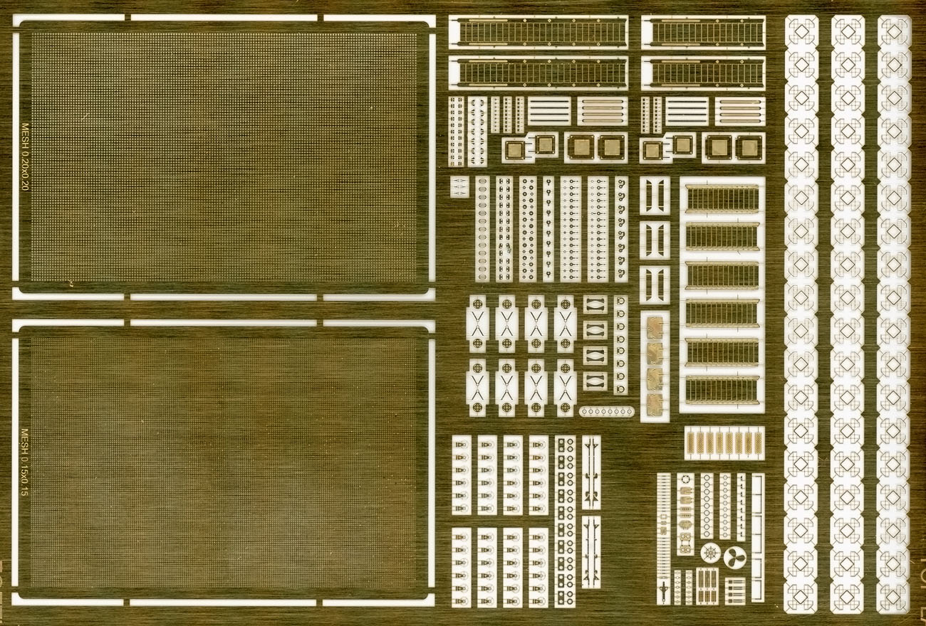
The artwork was sent to etchworks.eu and arrived three weeks later. This is only half the etch as a copy was added on the opposite side of the A5 sheet; I always add a few experiments and parts that are a bit finer than recommended by the etcher; some thin lines are over-etched and some grids and holes a bit under etched but generally a scan of set looks great.
All etched parts in place; most of it went fine except for the steering pulleys near the steering wheel that were too small; I gave up and added a tube. The grid on the stern was replaced by the newly etched mesh, a decision that came with some regret as I first had to repair the damage from removing the previous mesh. For the two small small ‘steps’ in the aft seating area I found out I did not have any folding lines on the rear of the etch (put some parts in the wrong layer when creating the PDF for the etcher); except for these only two other parts are affected, fortunately. The handrails are drilled in a bit to make sure they don’t fall off at the slightest touch (now they fall off at the merest touch).
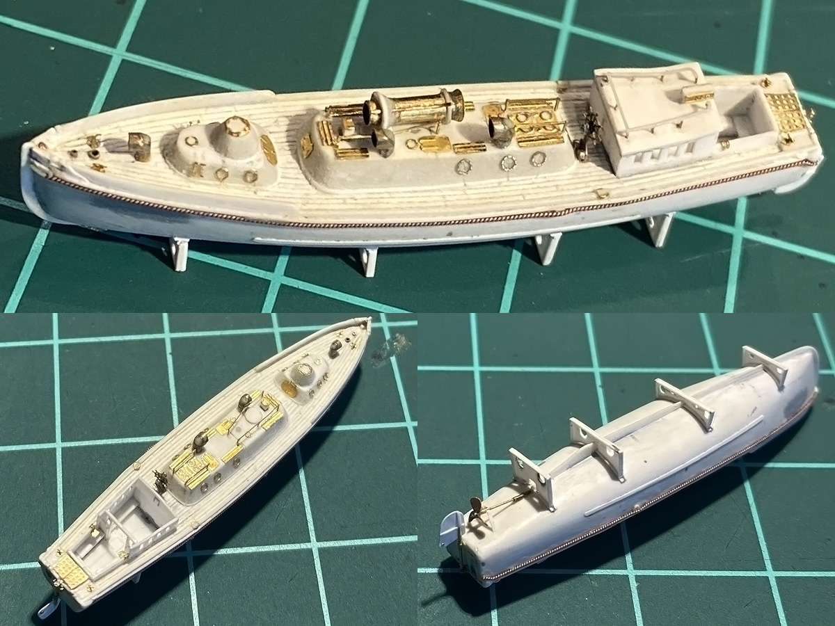
The crutches follow the hull lines of the barge, but their spacing follows the 4ft frame spacing of the boat deck; the crutches are spaced at 3 frames, except for the last crutch at 2 frames, positioned just below the stern tube. I started with the 2nd crutch working in either direction, choosing the keel to run level so that the propeller doesn’t foul the deck. Each crutch starts as a strip made to fit the pinnace; weight-saving holes are then drilled in and the strip is trimmed to size. The real boat rested on a teak planks but rather than putting a strip between the hull and the crutch, there are a few strips on either side of the crutch so that the crutch doesn’t need to follow the hull lines perfectly. There’s a bit of damage near the bow as I put the forward crutch initially at 2 frames; I also had to make 4 versions of the rear crutch before it looked fine; only one very tricky part and 13 strips to redo. Propulsion arrangement was last with the rudder being particularly tricky and very fragile.
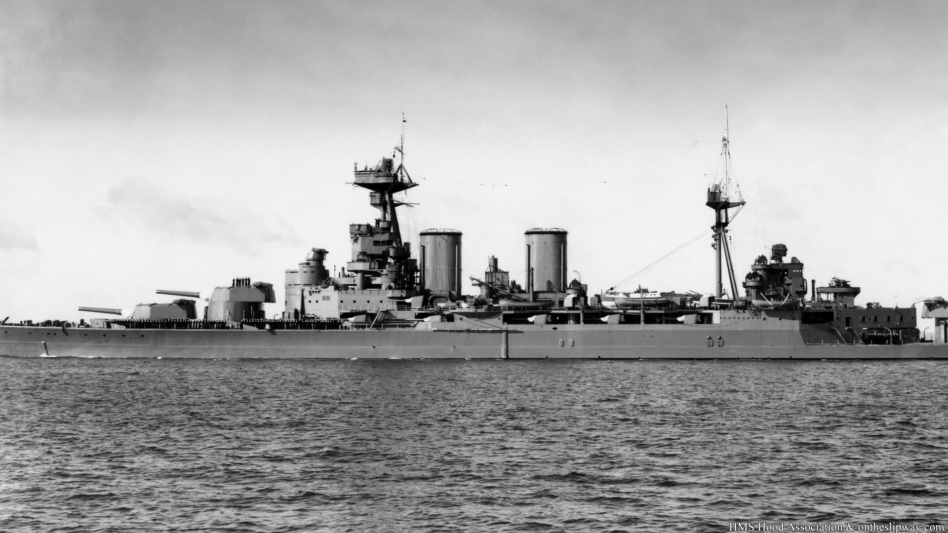
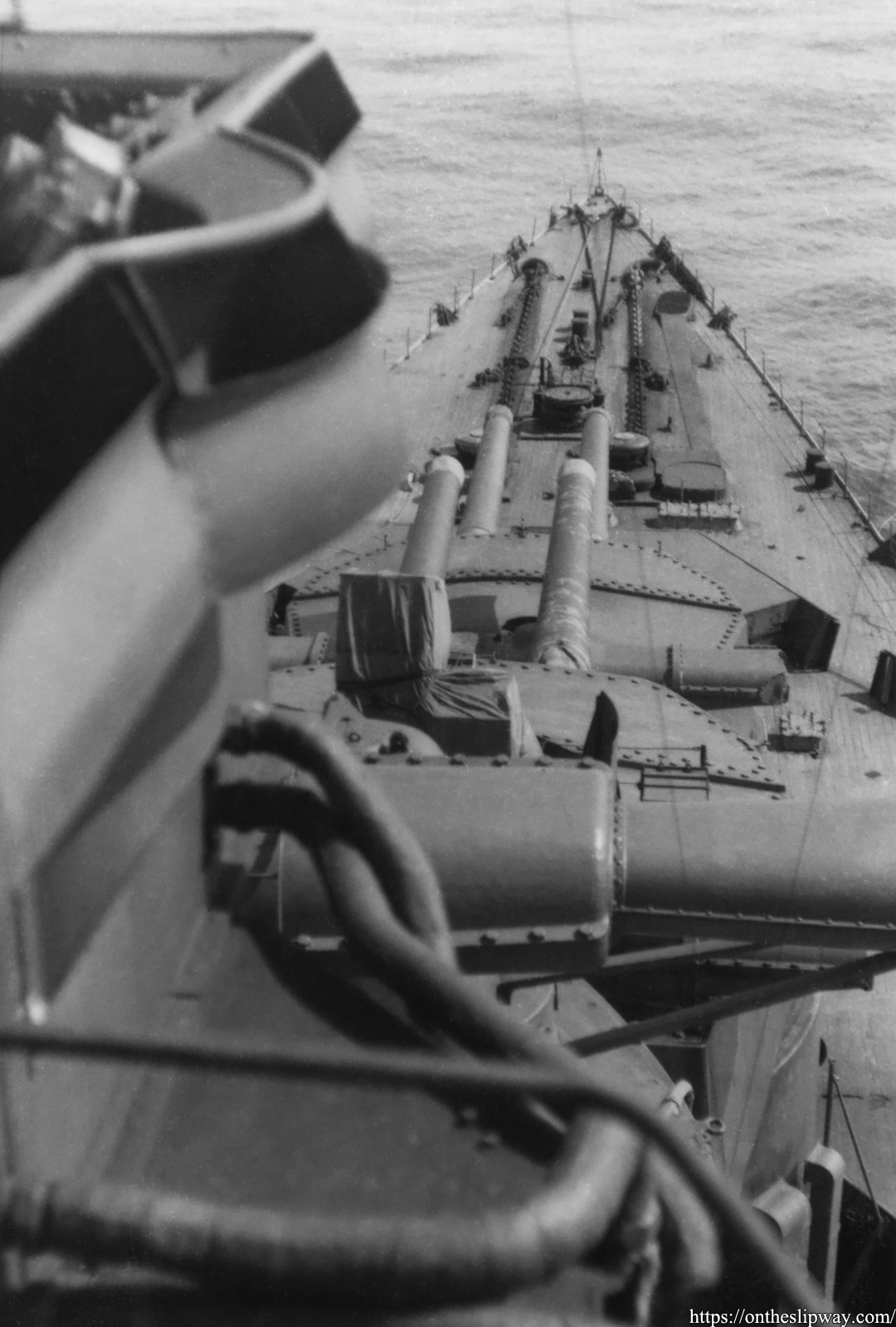
Random collection of images bought over the years; copy of a previous post with all images now at high resolution plus a few new ones.
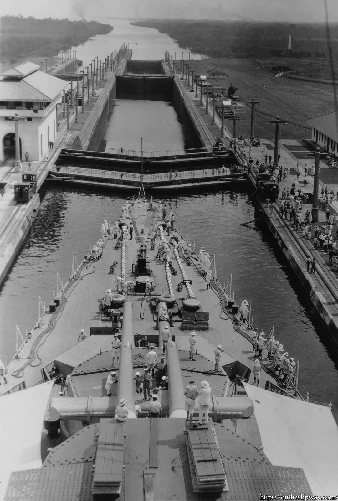
HMS Hood transiting the Panama canal, 7th of July 2925
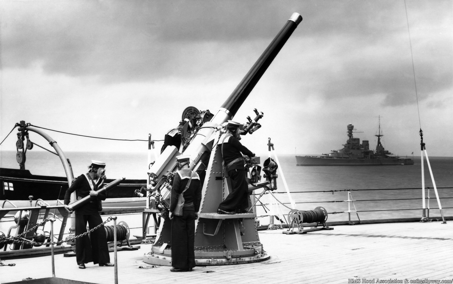
1932 (HMS Renown in the background)
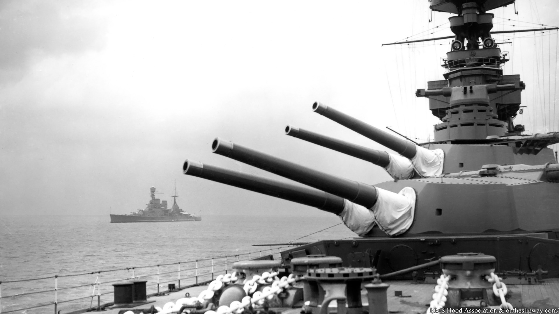
1932 (HMS Renown in the background)
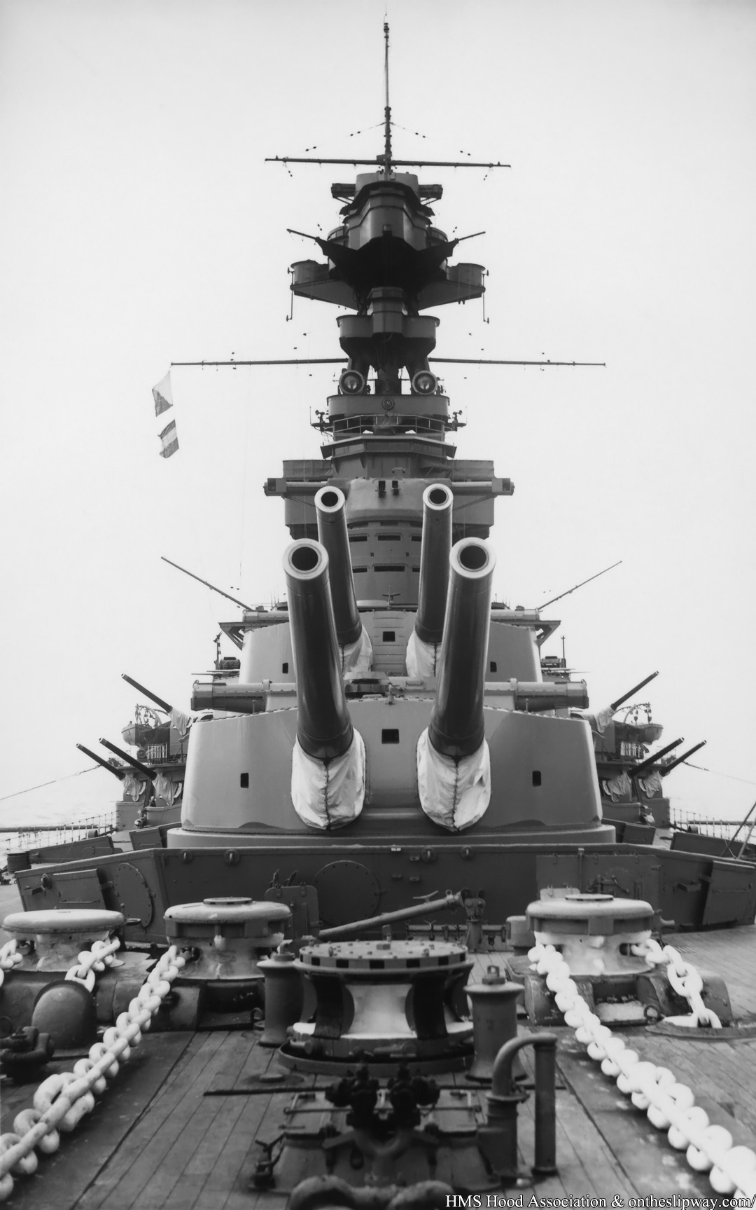
1932
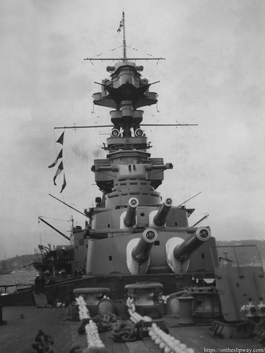
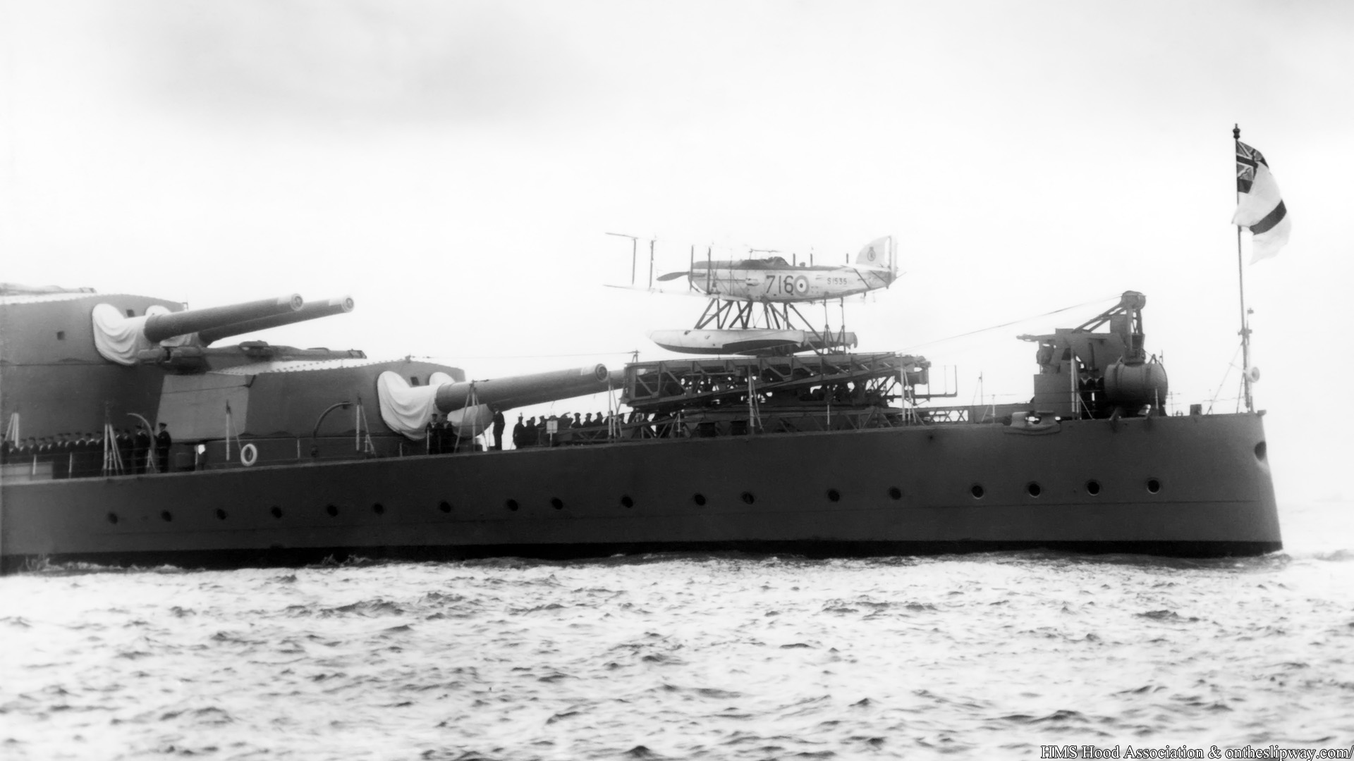
Not dated, but the aircraft equipment was only present from 1929 to 1933.
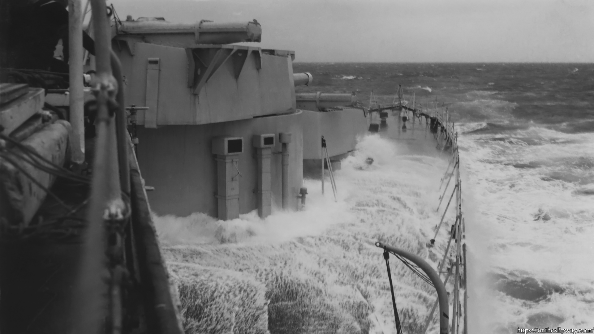
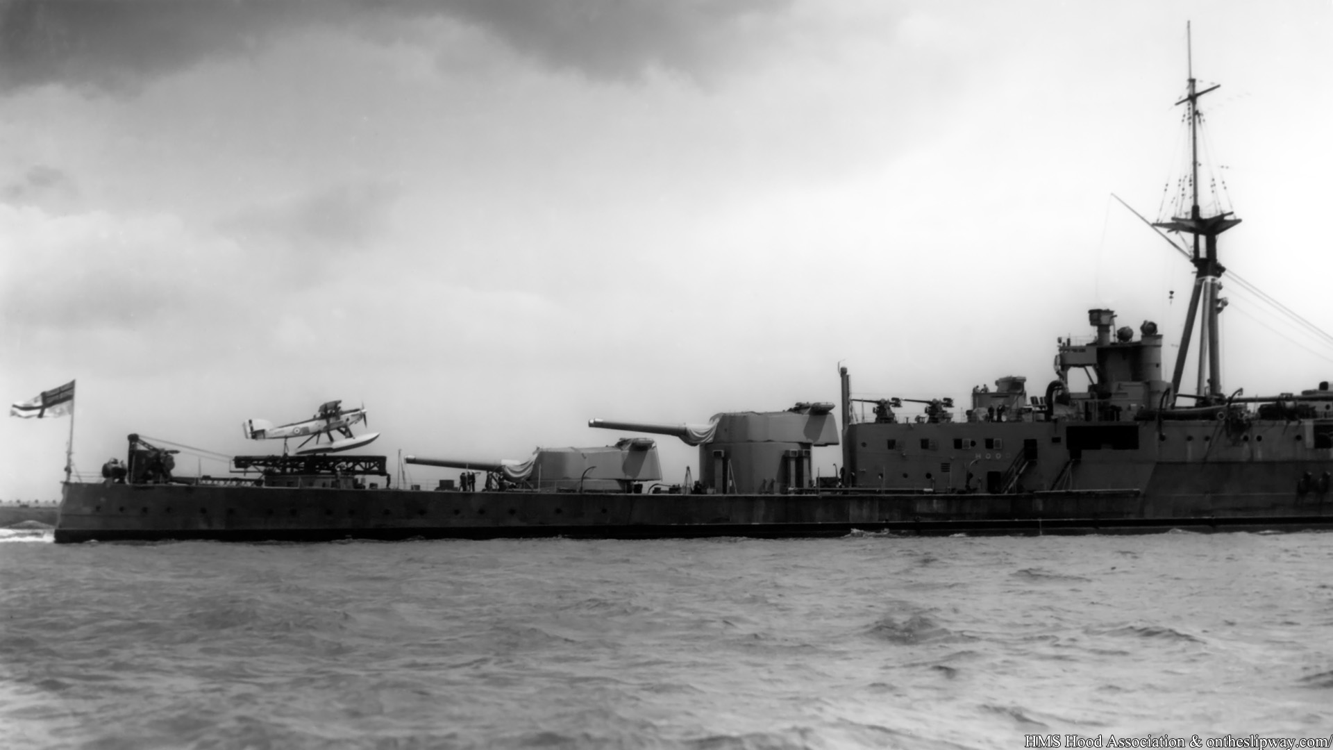
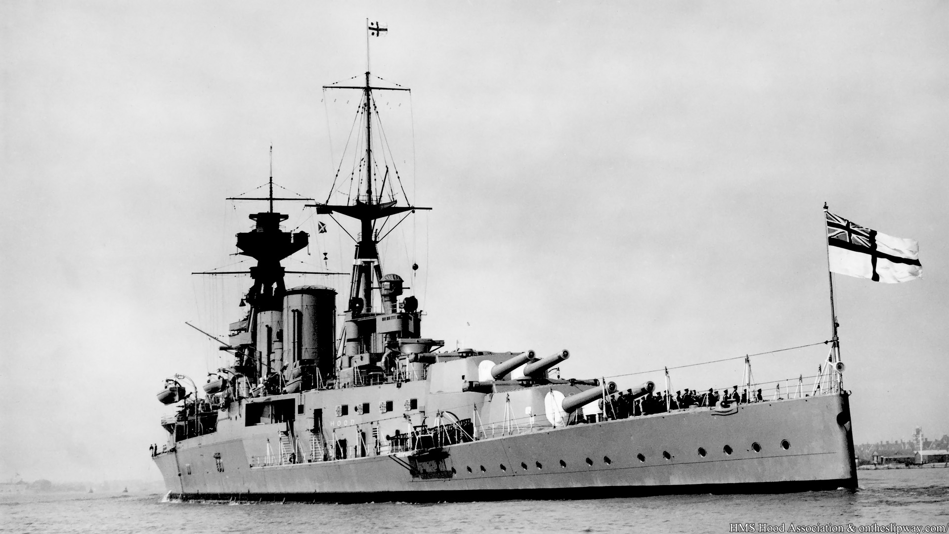
HMS Hood at sea with her quarterdeck awash, one of the reasons here quarter deck aircraft equipment was removed in 1933 (gun blast succeptibility being another). Hood’s freeboard was initially called for to be high and uninterrupted with her secondary armament placed high above the waterline. In the final design the stepped freeboard did not meet this demands but was not lower than her contemporaries. However, with her increase in armor following lessons learned at Jutland her stern draft was 2ft more than designed, without any major modifications on her outer hull (rebulging) her draft increasing over years and with Hood sinking in about a foot at high speed too meant her final freeboard was too low and the quarterdeck was frequently flooded, earning her the nickname of being the largest submarine in the fleet. One wonders how much the stability requirements and heavy weights of the superfiring aft turrets pushed the quardeck down and how much design freedom a single tripple turret would offer (a 3×3 15” was considered).
Remnants can be seen on top of X-turret on a platform removed in 193 1 (temporary mockup), kept until her loss (last part of this platform was later truncated).
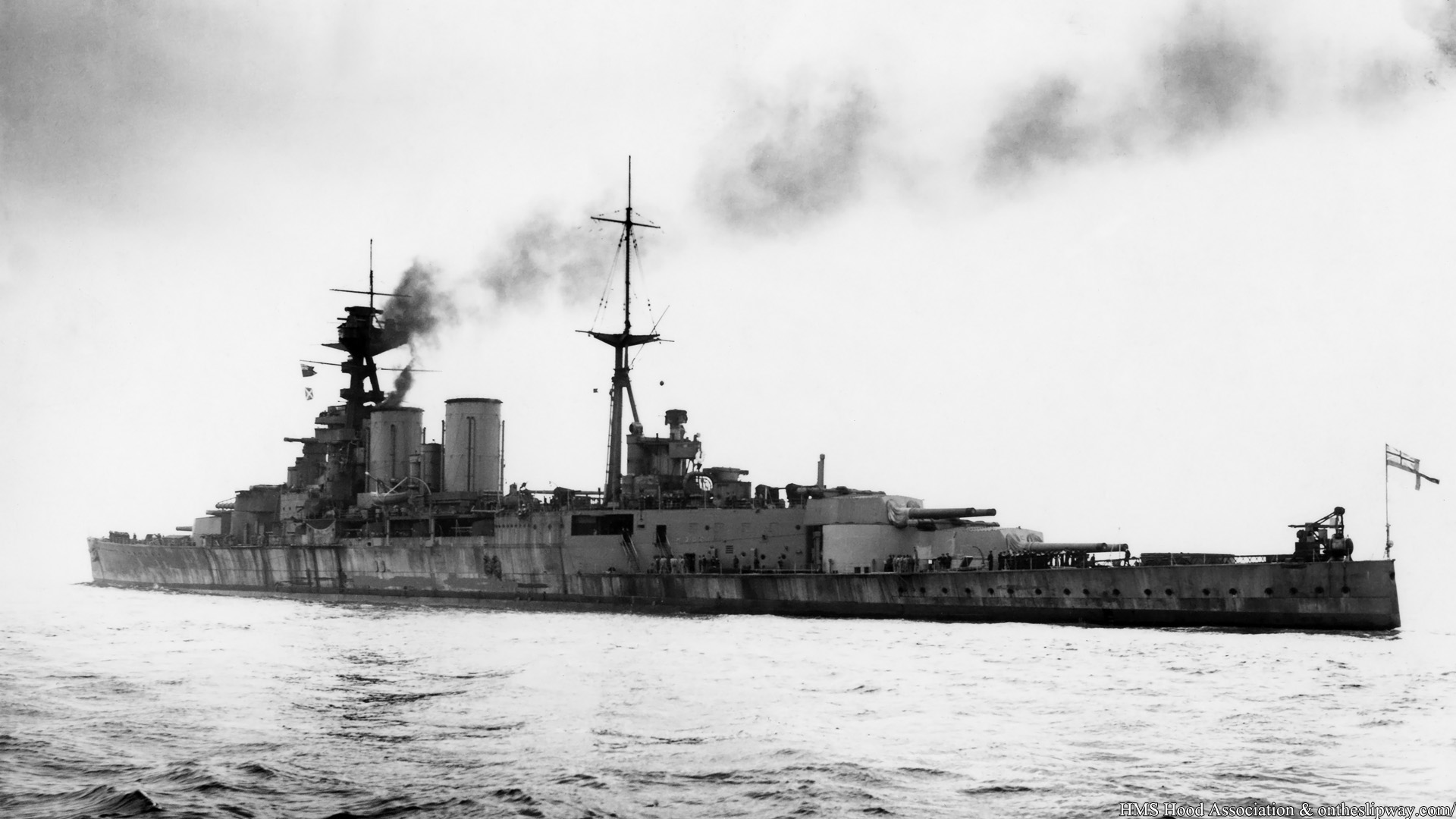
October 1936
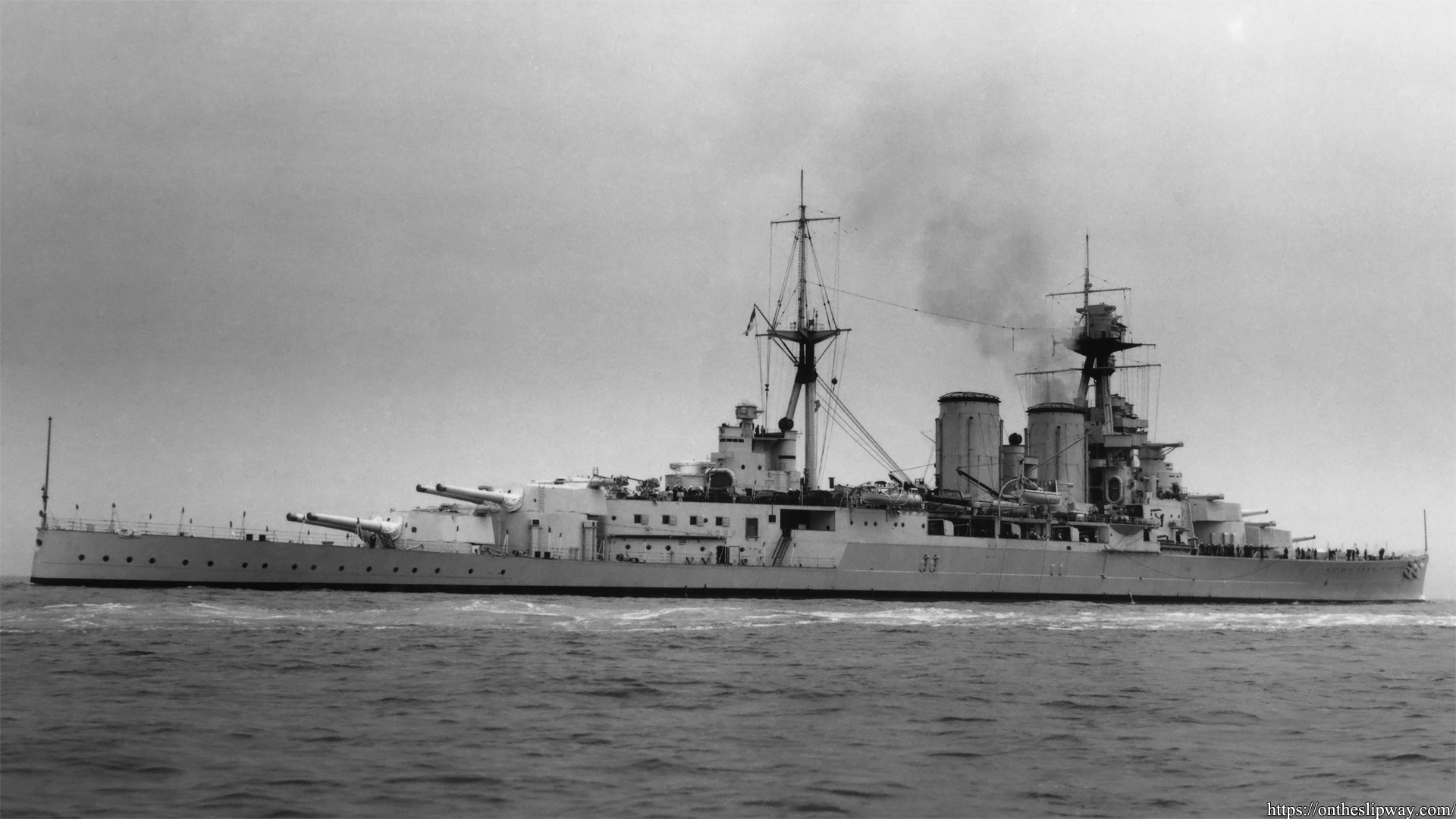
Gibraltar, 4th of October 1938. Note the neutrality markers on B-turret used during the Spanish civil war patrols (Red/White/Blue forward to aft). See wiki: International_response_to_the_Spanish_Civil_War.
1939. I think this is the nicest photo postcard I ever bought.
1939
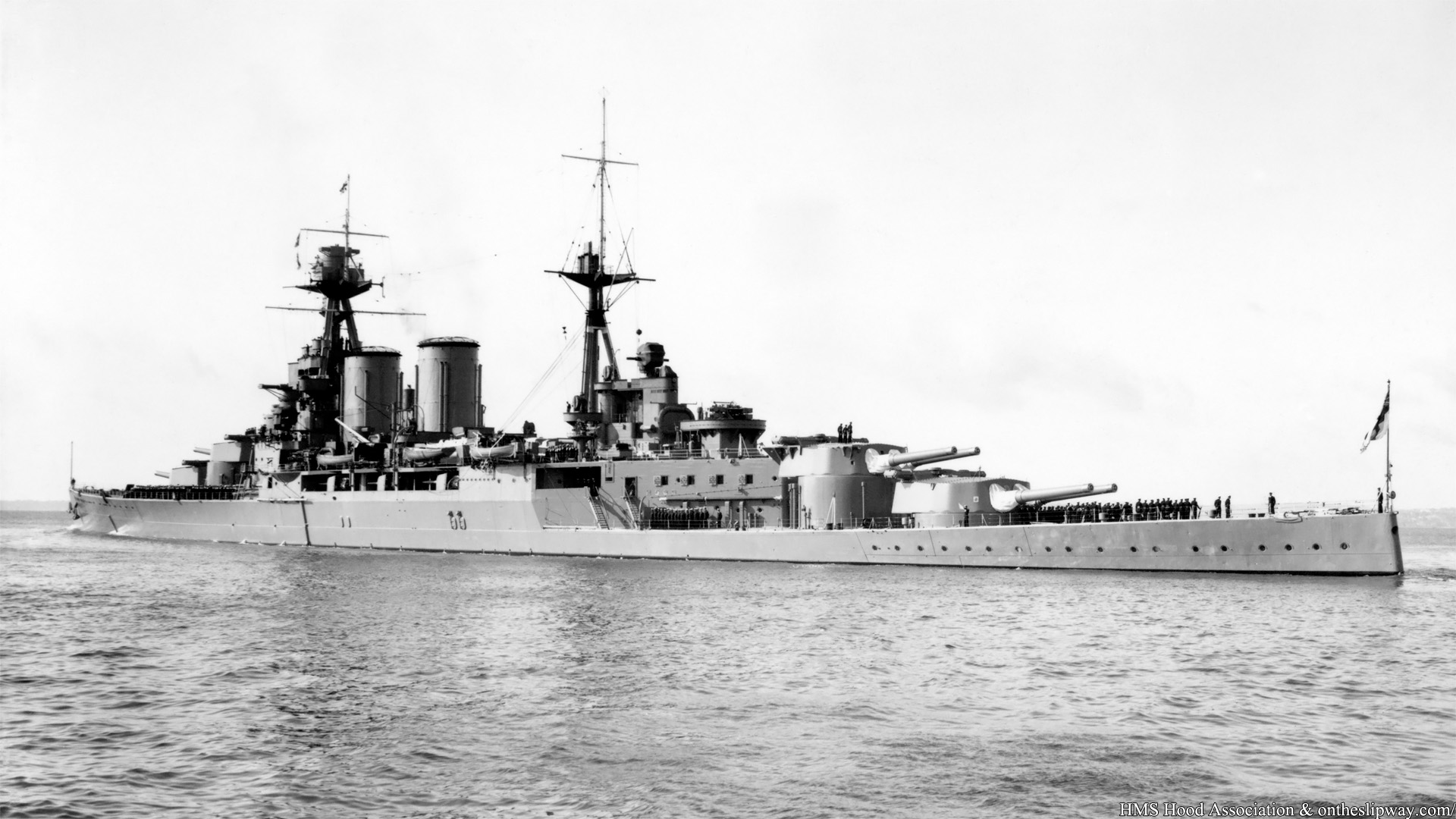
Image appears to be taken moments after the previous shot (Note crew on B-turret,near X-turret and near the whalers).
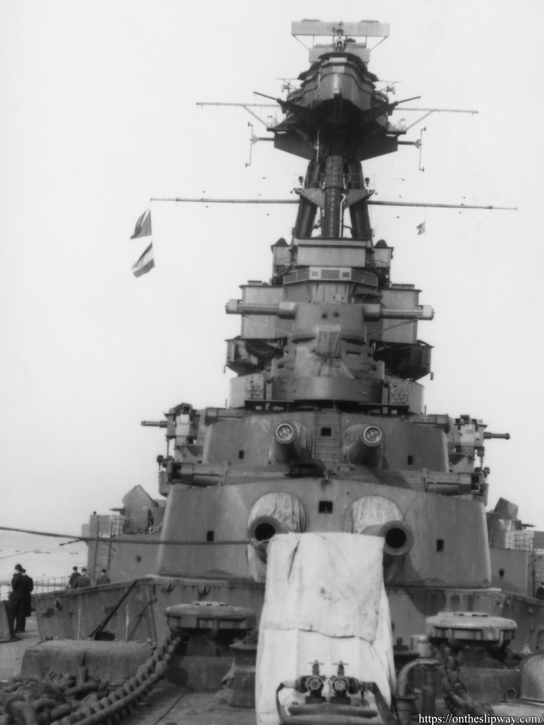
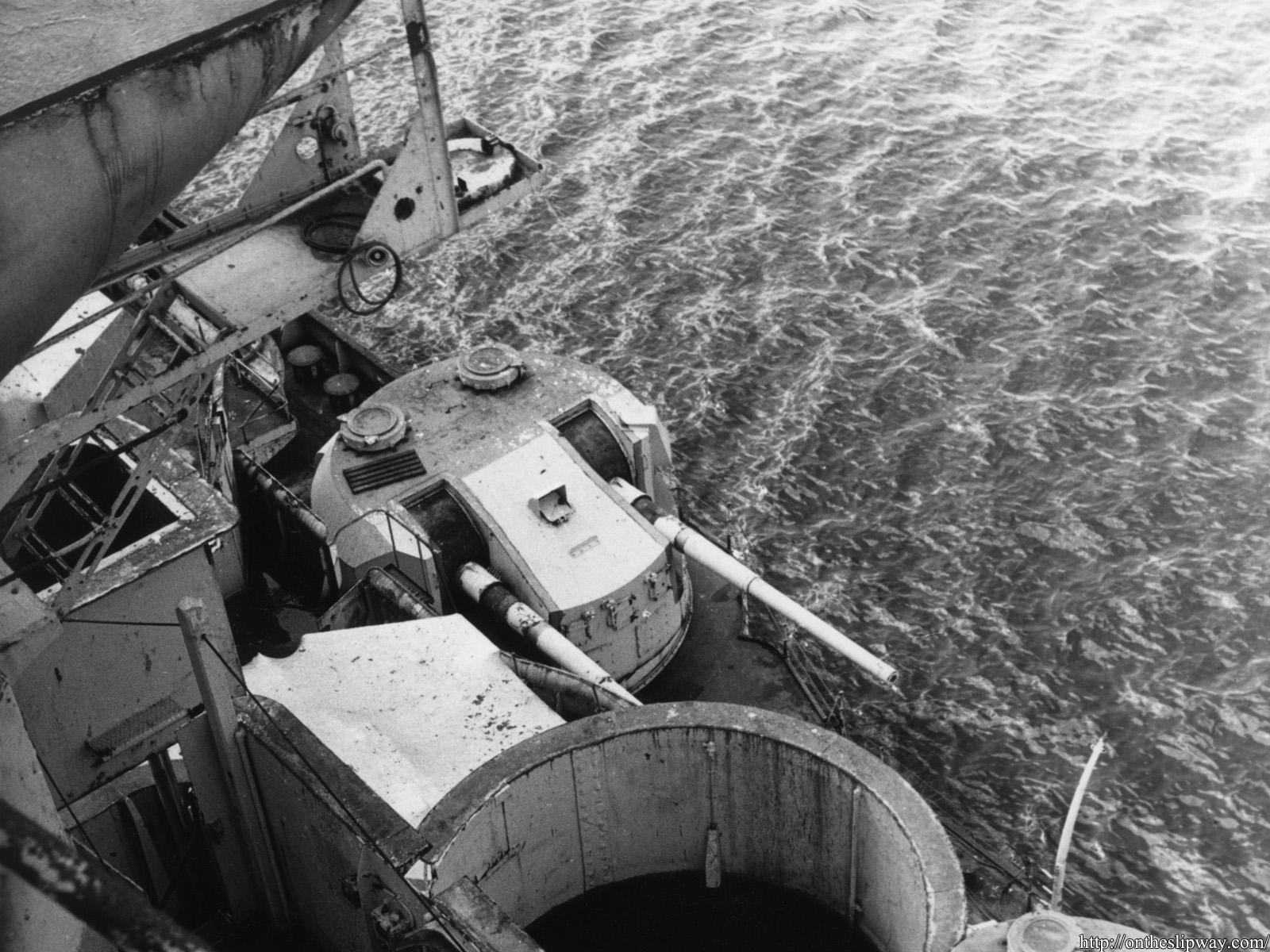
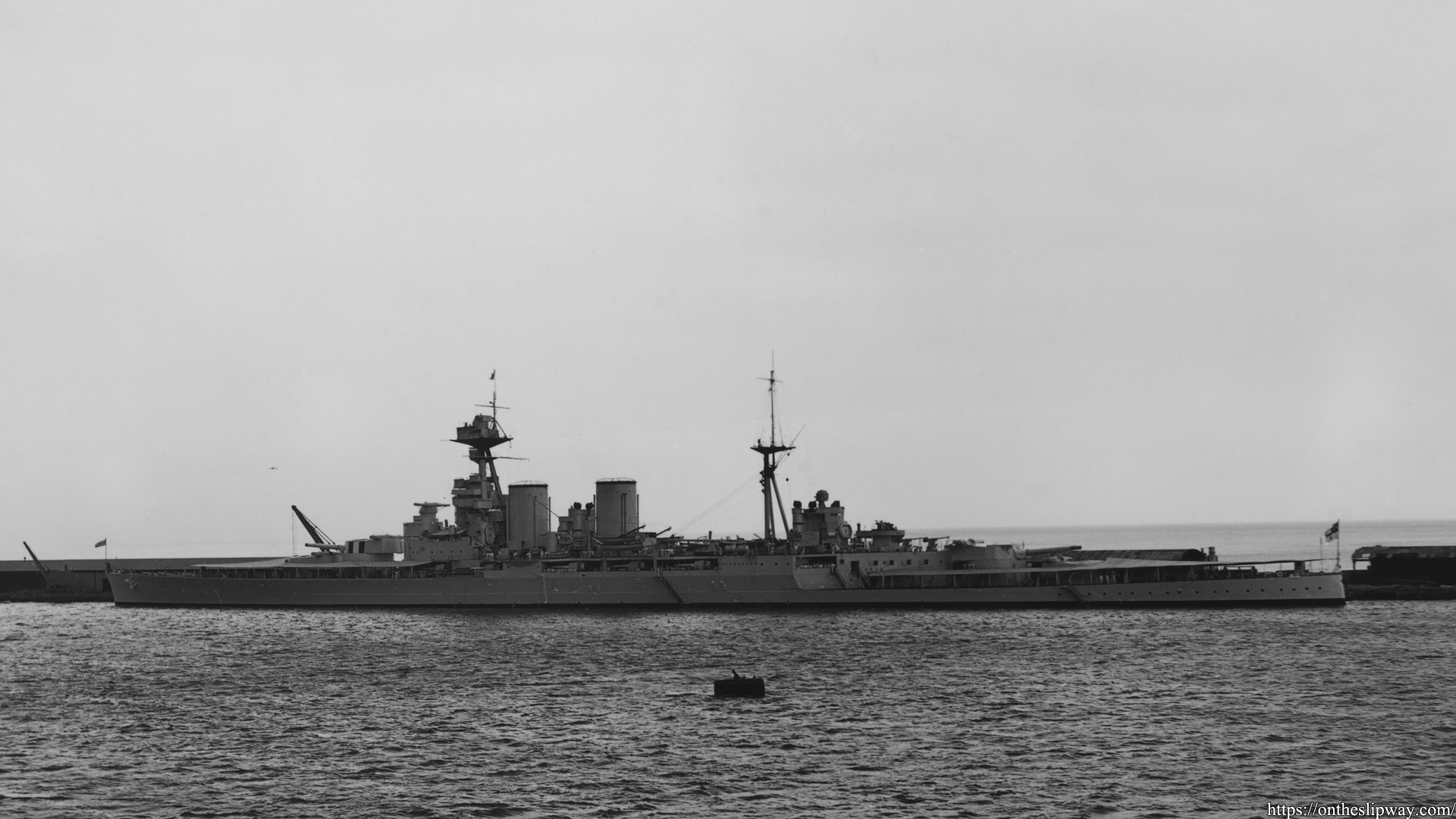
HMS Hood in her final appearance with the (covered) UP launchers visible on B-turret (and in the rear visible on the shelter deck), as well as the type 284 gunnery radar on top of the director control tower.

25th of March 1941. Note the roundel painted on top of A-turret; first appearance as a neutrality marker during the Spanish civil war (1937-1938), but not removed after. Colour unknown.
1940. Footage from 1940-1941 showing anything in detail is really rare. This one show the aft disinfector house between the forward searchlights and is a typical example of the crew paradox: the shot was taken to capture people living and working aboard HMS Hood, but they are also blocking the view to the ship.
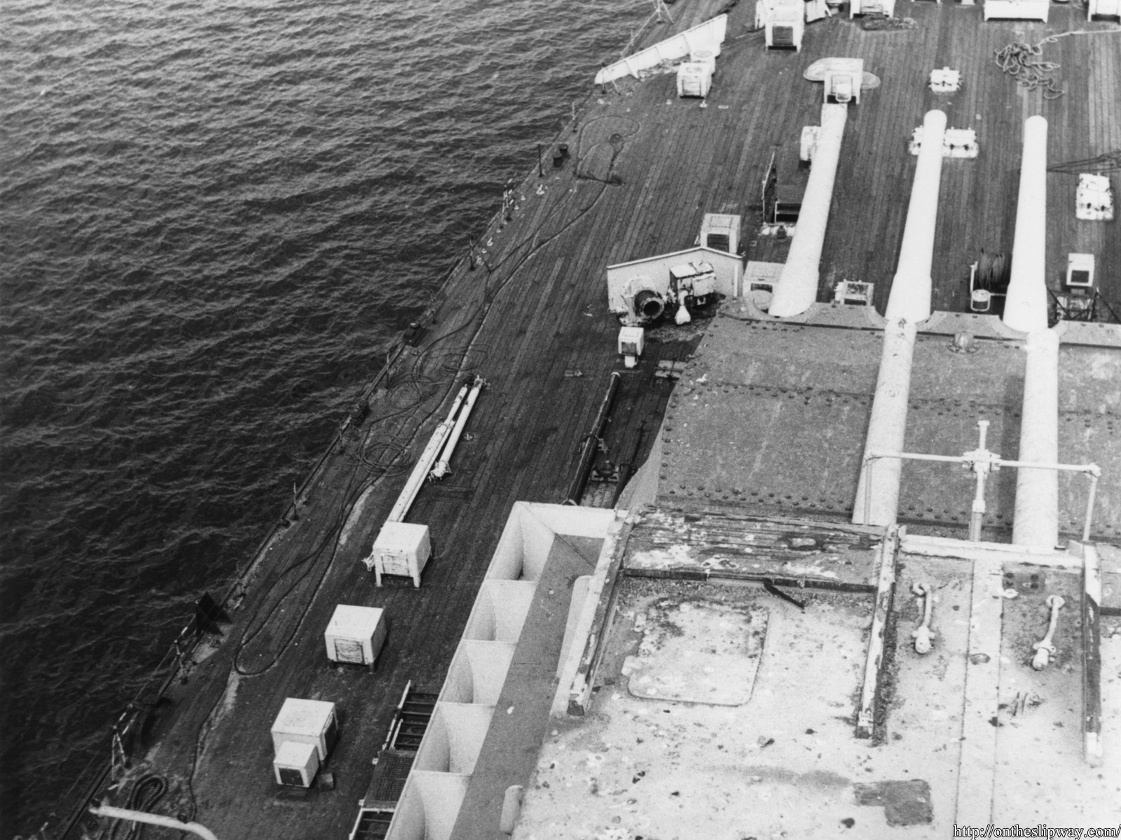
1940. A well-known shot of the main deck; we now know Semtex was applied on the ‘wings’ of the boat deck explaining its light one.
1941.
1940, Forth bridge in the background
Copyright © 2026 On The Slipway
Theme by Anders Noren — Up ↑