Category: Main mast

Radar Type 279M

As I explaining in my previous post of the main mast, the main topmast was removed from the main mast and replaced by the aerial for the Type 279M air warning radar. An aerial is an antenna in military terms. This system normally operated with a transmitter and a receiver array for the Type 279 radar (and later the Type 281). HMS Hood was the first ship fitted with the experimental Type 279M aerial, whereby the aerial was a transceiver array capable of both transmitting and receiving requiring only a single aerial. This is clearly sited on the radar page and this transcript on the official Hood site. If you want to know more, or even everything, about the Type 279 radar aerial, please go to the Royal Navy’s museum of radar and communications website, a source of information the likes of which I not seen before. I cannot find any more information of the Type 279M in particular, nor is it mentioned in the article “The development of Radar in the Royal Navy (1935-45)” by Alastair Mitchel in Warship, vol IV, pp 2-14, pp 117-134. The M designates the first major modification although the Type 279 was in itself an update of the Type 79, and other transceiver arrays are usually  marked with a B (single mast version) and no other instances of an M variant were found.

Pictures of HMS Hood taken weeks before her loss do not show the aerial clearly. But, at least there is ‘something’ visible. Unfortunately, the Type 279M radar is usual a ‘something’ on a picture, showing itself barely visible high up in the masts of battleships and cruisers. One must also be careful, as the radar aerial Type 281 (fitted with a Type 240 IFF antenna) looks a lot like the Type 279 (fitted with a Type 243 IFF antenna).

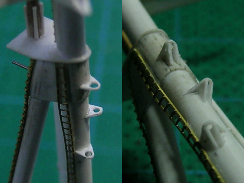
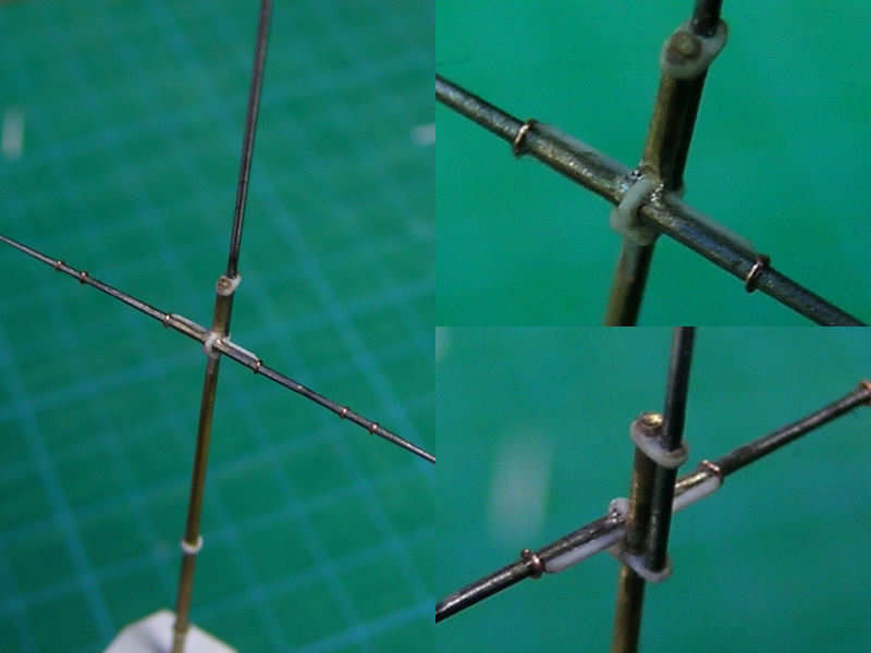
All these antenna do show to have a small service platform that seems to be standard on all vessels and Raven & Roberts “Battleships of WWII” & “Cruisers of WWII” show the same platform drawn on the masts. I assume that platform is of the same dimensions for both the Type 279 and the Type 281. The measurements of the aerial themselves are known, as the span of the dipole array is half the wave length of the system, and dipoles are a quarter wave length apart. The wave length was 7.5 m for the Type 279 radar

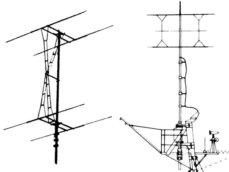
The left image is a drawing from Roger Hayward’s “Cruisers in camera” of the Type 279. At right, a picture is shown from Ross Watton’s “Anatomy of the ship: the cruiser HMS Belfast”, showing the Type 281. This was my best starting point for the Type 279M dimensions.

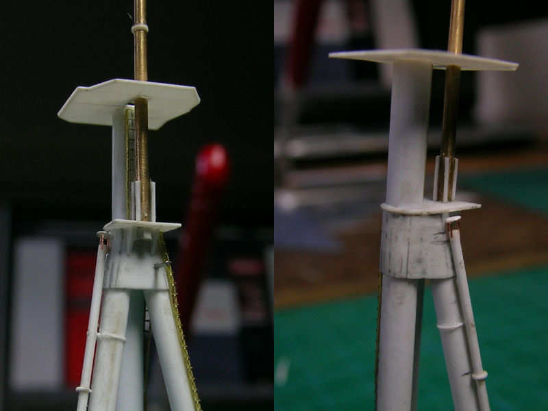
The best picture is from Roberts & Raven “BB’s of WWII”, page 387, showing the topmast of HMS Queen Elizabeth in 1941 and is the only good (if not excellent) photograph of the aerial. It also shows the gaff from the aft of the service platform that was present on HMS Hood as well. In order to access the platform, the ladder had to be on the front of the mast and this is visible on some pictures. The right half of the pictures shows the Type 279 (top row) and Type 281 (bottom row). Except for the differences in the aerials themselves, it appears that the Type 279 has one less masthead insulator and the platform support bracket near the mast is angled for the Type 279 and straight for the Type 281.

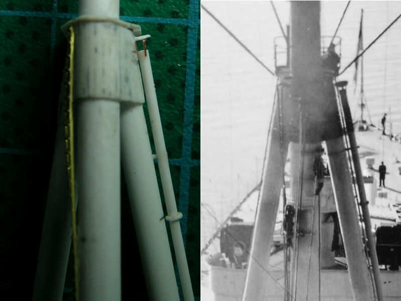
The mast of HMS Hood is seen “clearly” at left . Some cabinet is still present on the aft star fish. The right picture is reproduced from the Canadian Forces Base Esquimalt Naval & Military Museum with permission, showing HMS Hood in May or April 1941. The gaff is a clear indicator the radar platform was fitted and the platform and radar mast are visible, although just barely.

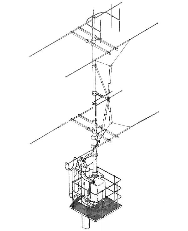
This image I found at the Royal Navy’s Museum of Radar and Communication. This picture (reproduced with permission) is absolutely fabulous, showing the Type 279 radar with the 243 IFF antenna in great detail, found here on the site of the museum (page 81/82).

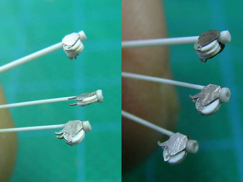
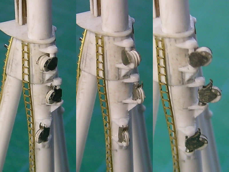
Having now spent a few days flipping through my books and seriously searching the net, I think I can now make a cute mini 279 aerial.

Main Mast, part II

The main crane derrick is operated from a platform at the base of the main mast. Two large winches are below the boat deck in the boat hoist compartment. Two cables run through pipes in the deck to a series of pulleys at the top of the tripod. One cable goes through the lower pulley and a pulley in the end of the main crane derrick, hoisting the boats on and off board, the other cable goes back and forth five times from the middle single pulley and two double pulleys—one at the top position on the main mast and one at the crane derrick’s end—setting the main derrick elevation.

The drawing in the Anatomy of the Ship series isn’t very accurately depicting the construction of the pulleys or the correct alignment along the main mast. The new position was determined using a series of pictures from this particular area. I started by adding the lower part of the frame of each pully, with a few difficult-to-cut parts. A series of supports are added to the frames, but as the wiring runs through these supports to the boat hoist compartment, and a double set of these supports is seen on the photographs.

The pulleys are an etched part plus the pulley themselves, made from 0.13mm Evergreen styrene. The pulleys rotate along an axis, but the wire as to be able to run downward with the derrick swayed to the side of the ship. I don’t know if the wiring runs through the pulley support, but it seems a logical approach. These supports were later replaced by steel tubing.

All pulleys in place. Note that the pulleys can swivel, following the position of the main derrick. The wiring, when the model is rigged, can still go around the pulley and through the supports. Not that I plan to have a fully operational 1/350 main crane, but it does allow for the use of only two wires to rig the entire crane (as in the real thing) and for alinging the lower pulleys toward the end of the main crane. In the outboard position, the pulleys are at an odd angle but that won’t be visible with the derrick in the stowed position.

mainmast_081

Main Mast, part I

HMS Hood carried a typical tripod main mast, with the topmast fastened with stays from the star fish. Several modifications were performed on the mast, including the addition of a radar set of which no drawing exist how this was actually done. The main mast is constructed from styrene and the top mast is a brass mast from modellmarine, made by Burkhardt Masch. I choose a mast with the correct lower diameter and taper, cut to length later.

Here you can see the tripod under construction. I choose to do this ‘in situ’, in order to have the tripod legs fit in their emplacements in the deck part and simultaneously have the mast completely up right. A small mould (tube) was used to keep the mast up. The small platform was cut at least 15 times before I had one with the right shape, with the small strip around the main mast of a constant thickness. That strip broke often all the time during drilling.

is a diesel exhaust pipe connected to the port side tripod leg. This exhaust is fitted to the tripod at three points. I first drilled in the exhaust pipe at the correct locations, taken from the best photograph I have to the mast taken f om the bridge, and then drilled-in in the tripod through the exhaust pipe. Next, I made several rings simulating the flanges keeping the individual exhaust pipes together. Of course, you can use rods and disks, but a single rod and rings is structurally more sound, especially with a few drilled-in holes. After the pipe was glued to the tripod mast, the rings were glued into place. A protective cover is fitted to the base of the exhaust pipe. My guess is that this cover is fitted in order to avoid damage when handling the admirals barge that is stowed very close to this location.

Each tripod leg is fitted with a ladder. I choose to use ladders by Aber, which I considered the best ladders available. They need to be folded, which is very tricky for longs lengths of ladder, but they can be directly glued to a bulkhead without additional supports and drilling in that usually spoils the fine feel of the etched part. Note the odd curve in the ladder as it approached the lower platfrom below the main starfish. I also added a cover to the diesel exhaust pipe, estimated dimensions from the photograph at right.

A nice detail shot of the main mast below the yet-to-be-fitted star fish. A small ladder runs from the upper platform the star fish. The main topmast housing is fitted to the bottom of the topmast. There are several nice drawings, but none to scale. This part will require more detail. A small metal tube is seen sticking out of the rear of the mast where the tripod legs meet. I have no idea what it is and it isn’t on any of the drawings, except vaguely on a few photographs.

A nice close-up of the topmast and wireless yard. Drawings of this yard are much better in Anatomy of the Ship: Warspite, by Ross Watton, including how the yard was fastened to the topmast. I like this detail, I haven’t seen it before on 1:350 models. The yard arm was hard-soldered to the topmast. Normal soldering resulted in a very weak bond and I didn’t like the prospect of gluing. With these scratchbuilding projects, the chances of handling damage are must greater than with kits, so I wanted a strong bond. I bought a Proxxon torch and started practicing hard-soldering. This is really tricky to do and more often than not I completely vaporized the brass parts. This is why the topmast and flagpole are made from steel. But even then, the solder wouldn’t flow between the two parts no matter how careful I was with adding flux and aiming the torch. I spent hours soldering wire together and in the end I just decided to stop playing around. Fortunately, the parts were soldered correctly in one attempt, with only some minor deformation in the topmast which was easy to remove. I added very small brass rings to the yard to simulate some much-needed detail. The flagpole is connected some distance from the topmast. To my surprise, the strength of the model is sufficient. Even more to my surprise, that flagpole was later removed to add the Type 279M radar antenna, which is a standard Royal Navy part. So, I snapped it off!

Copyright © 2024 On The Slipway

Theme by Anders NorenUp ↑