The degaussing cable proved to be a rather labour-intensive piece of detail. As you need over 2 meters for such a large model, you need a quick way to produce a lot of it fast. The cable was added to the etch set, but I wasn’t happy about the result at all. Also, from photographs of the ship, it is apparent that the cable was added sloppily, not at all as a straight and neat cable. So, scratchbuilding then!
I needed strip, a lot of strip, and with a consistent thickness. So, a short exercise in cutting lots of strip.
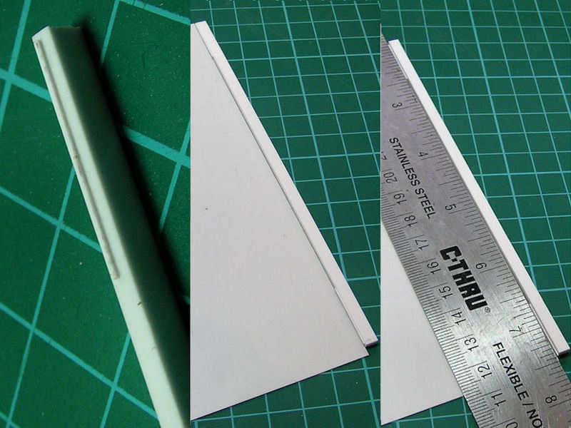
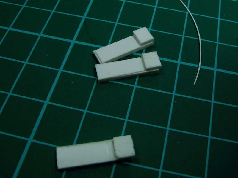
I start with some Evergreen strips with a smaller strip glued on to it (left). This smaller strip has the correct thickness for the to-be-cut strips. I put it to the plastic sheet (center) and then align the ruler (right). This gives you a pretty consistent strip thickness. I could have bought readily-available pre-cut strip, that is, if it were readily available and it isn’t.
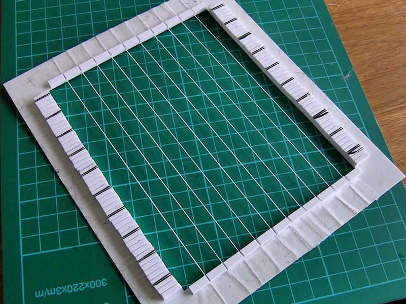
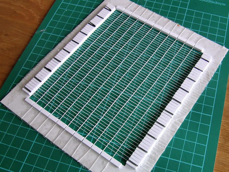
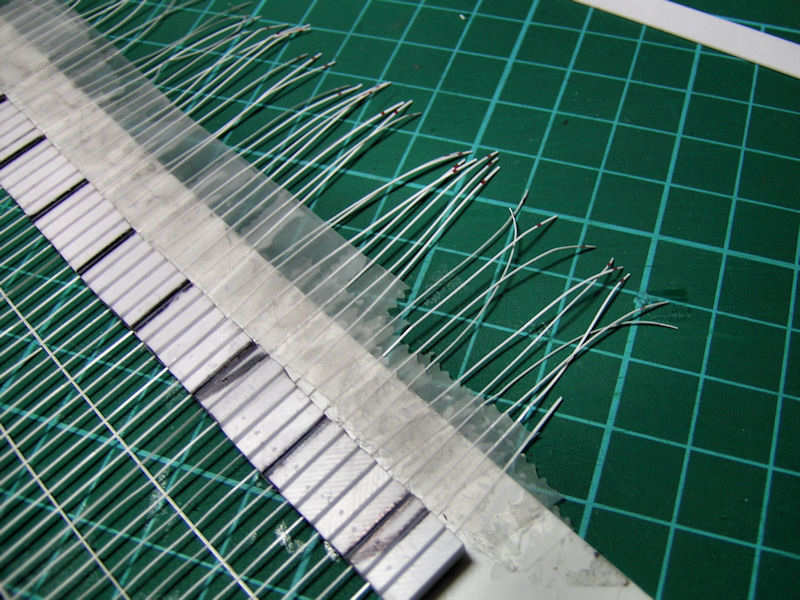
This is the gluing jig. Lots of plastic strip to help me with aligning all the parts for the cable.
Here ten new strips of degaussing cable are taped to the jig.
And here are, err, lots of smaller strips taped to the mould as well. They have already been glued. I tried a few types of glue, some gave a very brittle bond.
The smaller strips were made from 0.13mm Evergreen sheet, that is, very very thin. I marked the sheet with a red marker before cutting, so I knew which side should have been up. I also added the line to the other side, so that you can avoid glueing the strip without it being rotated along its longitudinal axis. Pretty difficult to see if lt goes well with all these strips so a bit of color helps.
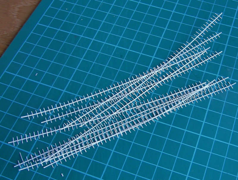
Once all the strips are glued in place, I cut the main parts loose.
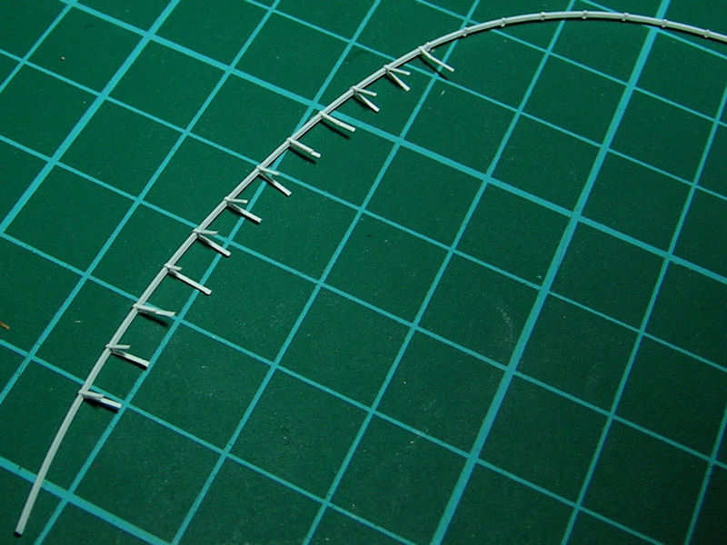
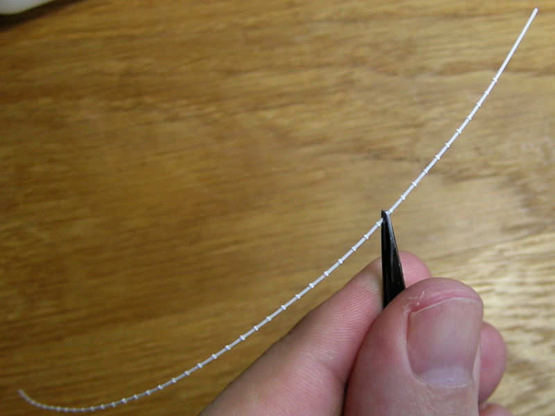
I used two tweezers to fold all the small strips: one for holding it at the junction, the other for folding. At this point, I started to loose a lot of strips (breaking or coming loose). Next, the excess strip was trimmed by pressing it down with a ruler just at the junction and then giving it a quick cut with a new and sharp blade.
Then it was sanded down and repaired when necessary. If the reparation was too much work, I just cut out a section.
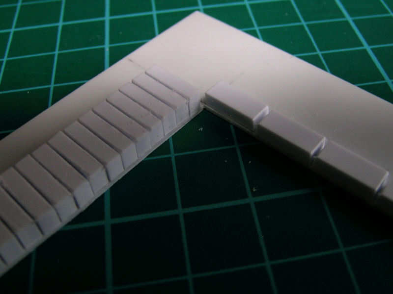
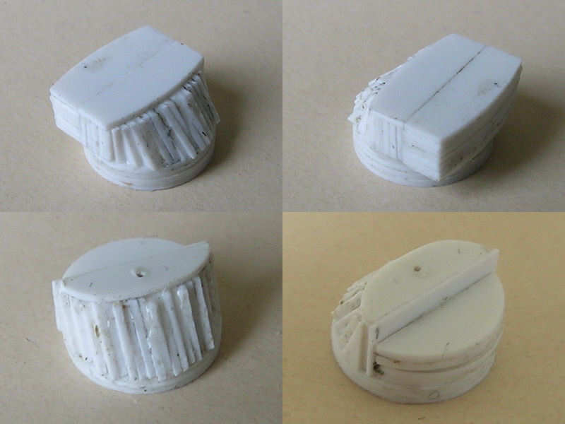
Before adding the degaussing cable to the model, I first had to add a small ridge on the exact side of the deck. These parts were very helpful in clamping a strip at that exact edge before fixing it with glue.
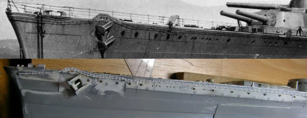
Hmm, that looks like the real thing, much better than etched cable to my surprise. Note how sloppy the real cable is and that the upper cable is slightly thinner than the other. And please don’t note that the portholes aren’t really where they should be. I’m not going to fix that…
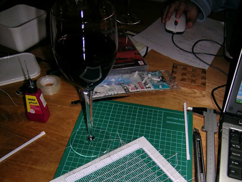
I only had 7 sets to build, so doing it while being drunk alleviates the effort. I had all the cable I needed, but left one set on the table and I have cats. Guess what happened? I’d never thought they would do that…


