

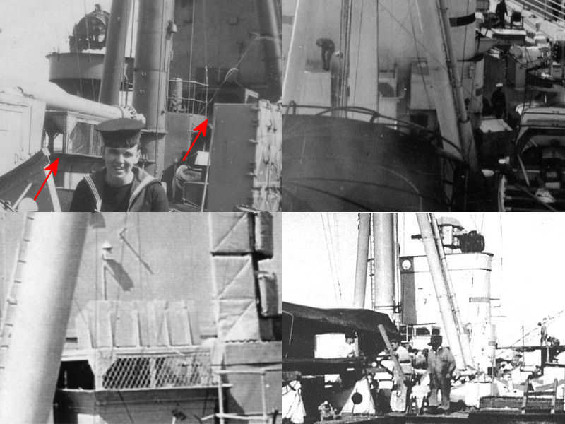
A series of boiler room vents runs through the bridge superstructure and next to the funnels. On all the drawings, two boiler room vents are drawn at the bridge location, but only one of them visibly exist the superstructure on the admiral’s signal platform. So, where does the other one end up? The top left section of the image shows the rear of HMS Hood’s superstructure, with the arrow indicating the exact location of the after boiler room vent. The other vent is seen on the image section next to it. The top right image shows the implementation on the model. I’m not exactly sure if the aft vent is correct, but this is all the material I have. The bottom half shows both vents in detail. The vents on the admiral’s signal platform intersect the base of the 5.5″ rangefinder towers.
There are four large engine room vents on the boat deck, all situated on the center line of the ship. The top left image shows a sailer posing with one of these vents in the background. A little to his right, the vent near the searchlight platform is visible. Notice anything? This vent is considerably taller than the other vent, which is not indicated on any drawing of HMS Hood. The other pics show the same vent in detail. It’s very easy to overlook the height of this vent, until you actively gauge its height from nearby details. It’s nearly twice the height of the sailer standing in the top right image. The top left image shows that a series of hatches are present on the top of the vent, including a small ridge around it.
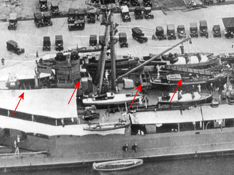
This image has the location of the vents indicated. Notice that all hatches on top of the vents are opened toward the stern of the ship. It’s difficult to make out the outer right vent and I can’t tell if hatches are present. Probably not, as the main derrick is stored on a crutch on top of this vent, blocking the hatches from opening. The vent near the disinfector house (second from the right) is also blocked by the main derrick, but is built wider with hatches capable of opening when the main derrick is stored. This might be true for the vent at right as well, but I cannot find any picture showing this, with all the boats and launches stored there blocking the view. If hatches are present, I’ll add them afterwards as I’ll have the main derrick in the stored position on the model.
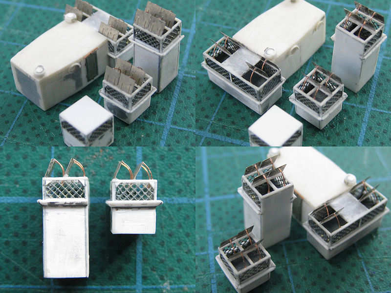
Here are the vent models that took a surprising amount of time to complete. I started by cutting strip to size, added wire mesh, cut the strip to height and width, and glued them to a rectangular base. A small 0.25mm strip was glued to each corner. The roofs are frameworks of 0.25mm strip as well. Small triangles were added to the corners of the mesh (difficult to do) and custom-etched hatches were added later. The hatches are fixed using arced supports, visible when stored in the top left of the previous image (behind the sailor).