
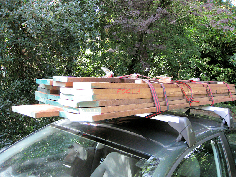
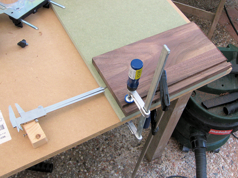
I decided to make the speakers from American Walnut bought in the wood harbours of Amsterdam. It’s very expensive to have rough timber cut the panels of an exact size so I learned how to work with the overhand planer (surfacer) and the thicknesser (vandiktebank) at work. I made strips of 90 and 110 mm wide, glued them together and cut them to the correct thickness. I spent nearly three days in the woodworking workshop explaining the high price of custom-made panels admirably.
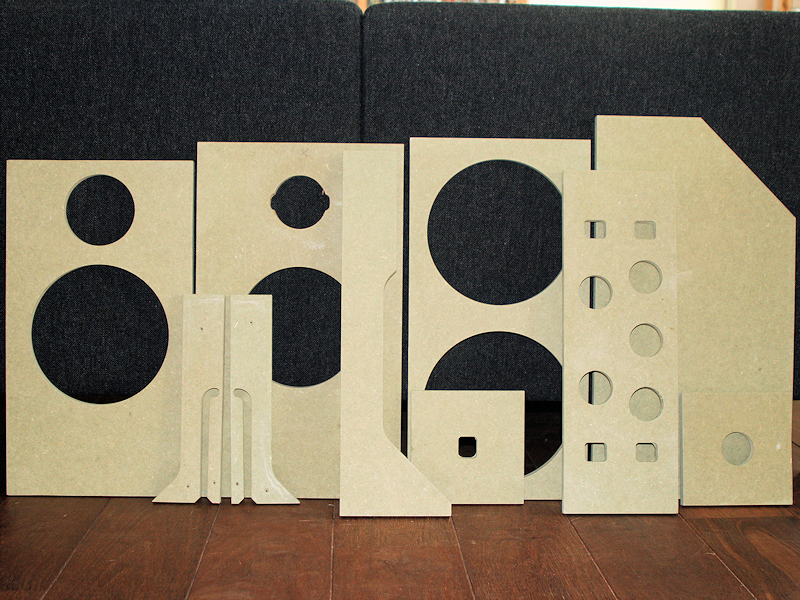
I had a few templates made by a CNC router from waterproof MDF, including templates for the floor hatches. The template at the far left is a bit smaller than the panel next to it; this was an error of the milling company but it worked just as well.
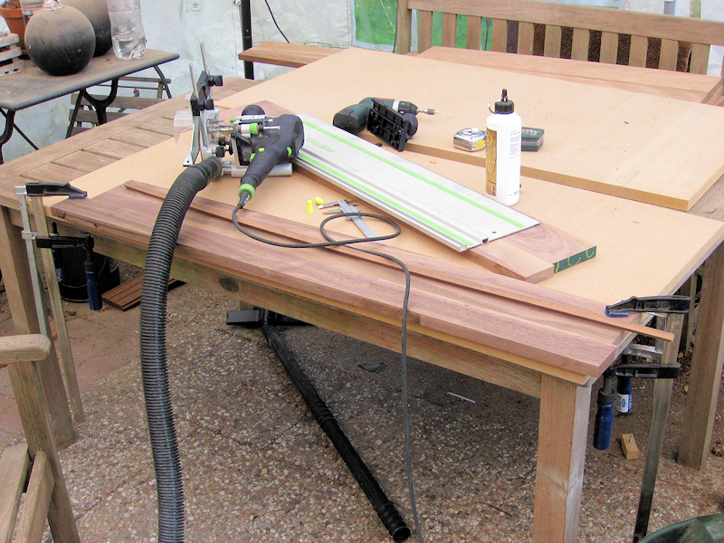
I do not have a nice workplace so I worked outside. I just clamp down a panel and start sawing and milling away with the router.

The panels weren’t sawed but milled to size with a template. Not overly accurate perhaps, but a good alternative to not having a decent table saw. Note the damage for this board that fortunately fell in a driver position. I’ll have to pay more attention when buying wood next time; this panel was too thin and couldn’t have possibly been suited for a decent panel.
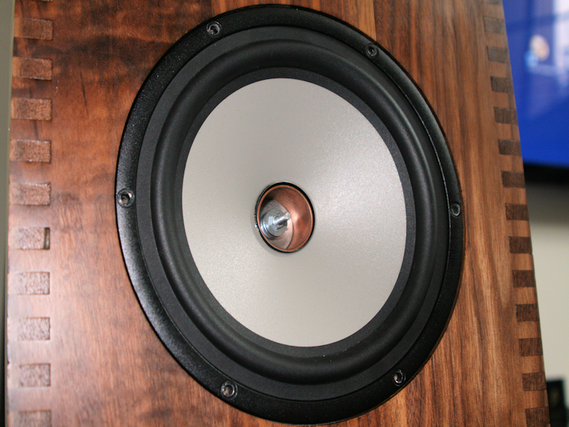
This is one of the smaller cover plates of the woofer cabinet with a channel for the wiring already in place. This channel should have been routed after producing the box joints and assembling the woofer cabinet; lots of the box joint ‘teeth’ broke off during handling and fitting. For the midrange baffle you have no choice, the channel cannot be routed afterwards.

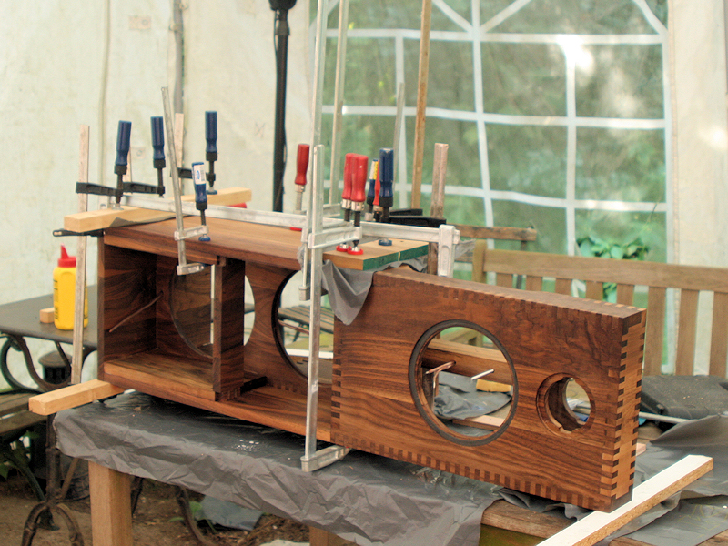
I also had to learn the hard way that when routing a circle that it’s best to use a jigsaw to remove most material and use the router to finish the circle off. If not, the disk being routed out of a panel separates from the panel and can bounce violently against the still routing router and panel. This destroyed one beautiful baffle. I also tried to route a wire channel through the side of this particular panel, leaving box joints 5mm thick and that didn’t work (1 panel ruined). I also changed the direction of the grain of the wood for the woofer cabinet cover plates (1 panel ruined). With all the practising, failed attempts and rejected panels I ruined enough wood for one additional Orion cabinet. Oh well, it’s a hobby.

The first parts were glued using a disproportionate amount of clamps. I used some random wooden strips to distribute the load and avoid the clamps damaging the speakers. Before you start gluing it is best that you keep filing away at the joints until the panels no longer require force to make a good dry fit. A proper dry fit will also ensure you’ll have the ingredients to quickly assemble the parts when gluing. I started differently and some of the joints, particularly for the front panel with the wire channel, bent a bit during assembly leaving an ugly pattern. I also learned too late that after the glue had dried (I wait for about three hours) you need to rinse the speaker and remove as much of the excess glue as possible (some say scrape excess glue, water may make the surface uneven). In any case, when you wait too long you can only sand the excess glue off and when the box joint isn’t flush you need to chisel it out between the recessed joints; not nice. Some of these beginner mistakes are still visible on the earlier-assembled parts.
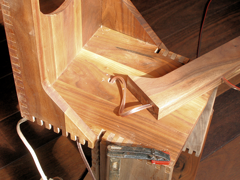
This is the support for the magnet mounting of the midrange driver. I used a rampa screw and M5 threaded wire to mount the driver, removing the screw that normally holds the midrange driver together. The wiring runs through the support and through the top plate of the woofer cabinet. I actually needed to practise drilling a hole that long. Drilling the final parts when I didn’t have enough panels left for a replacement was the most anxious moment of the build.
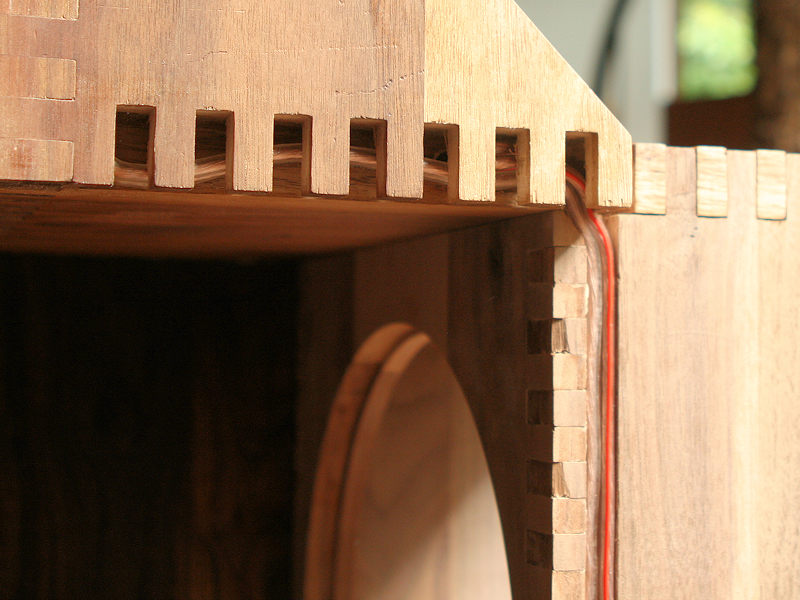
Here you can see the wiring of the tweeter and the midrange running behind a box joint; the row of box joints of the upper and lower side panel are only half as thickness of the panel. I carved a channel from the top plate of the woofer cabinet to the center panel.
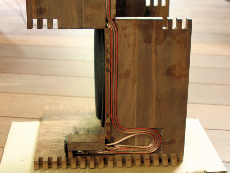
The two cables from the midrange baffle are joined by the two woofer cables. I later added the large recess to hold the cables in this folded position. Having a bit of extra length helped during assembly and should I have to resolder a connection I can at least remove the Speakon connector from the speaker. This was a very last-minute addition that was very convenient for the build.
A scary moment; the final panel is in place, covering up all the cables with no more room for repairs.
Here you can see the midrange driver without the phase plug. I started with the phase plug forcing the driver to its mounting but I later placed 15 washers and a hex nut. The phase plug is now screwed on with less force.

The cover of the midrange driver is still present. I cut out an opening and placed a few washers; the mounting is quite rigidly forced against its support. I hope the connection is strong enough or I’ll have to drill out the support and fix another nut & washer to the rear; now it’s a nice blind connection.
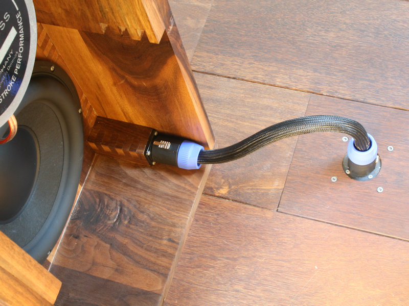
The Speakon connector fits in its own box-joint block. It’s a nice addition that was much easier to draw than to make!
Subproject complete!
Introduction
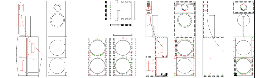
The plan
Design changes
Signal processing
The listening room
Production
Listening