Author: efoeth

Making rings with a Punch & Die set

If you have a punch & die set—either by Waldron of Historex—you can update the tool so that it can make rings. You need to have access to a lathe, or harass either manufacturer into producing an update set.

This is the Historex set. It doesn’t have the range of diameters that the Waldron Precission Punch & Die Set has, but I find it a very useful tool nonetheless (I just bought the Waldron set, but haven’t used it yet). The top-right image shows the set of sub-punches I made myself. Use a normal punch to first punch out a disk. Move the plastic sheet to the subsequent hole and use the smaller diameter of the sub-punch to align the part concentrically. Then you can punch out a small ring. The lower-left image shows the range and fineness of such a small ring that you can make. For example, I use the sub-punch set to make rings for eyebrows. Very thin rings often get teared to pieces, sometimes even depending from what side of the plastic sheet you’re working one.

This is a nice trick to make a good tool (albeit very expensive) even better.

Degaussing Cable

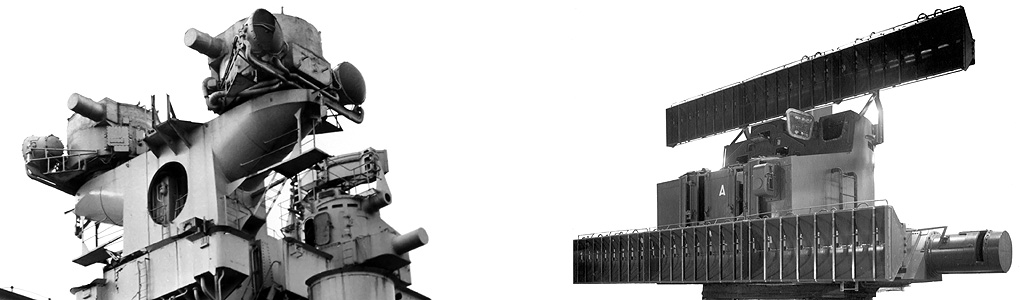
The degaussing cable proved to be a rather labour-intensive piece of detail. As you need over 2 meters for such a large model, you need a quick way to produce a lot of it fast. The cable was added to the etch set, but I wasn’t happy about the result at all. Also, from photographs of the ship, it is apparent that the cable was added sloppily, not at all as a straight and neat cable. So, scratchbuilding then!

I needed strip, a lot of strip, and with a consistent thickness. So, a short exercise in cutting lots of strip.

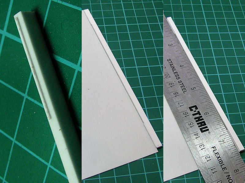
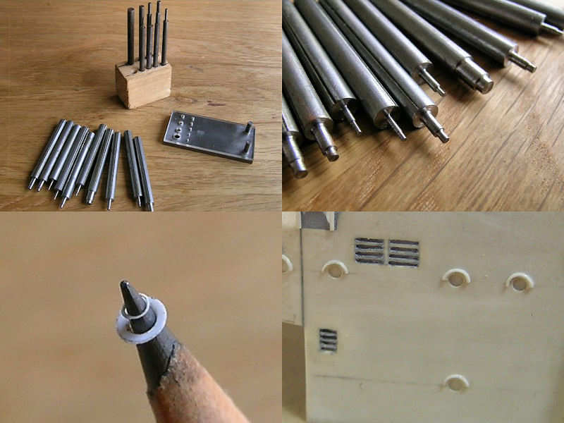
I start with some Evergreen strips with a smaller strip glued on to it (left). This smaller strip has the correct thickness for the to-be-cut strips. I put it to the plastic sheet (center) and then align the ruler (right). This gives you a pretty consistent strip thickness. I could have bought readily-available pre-cut strip, that is, if it were readily available and it isn’t.

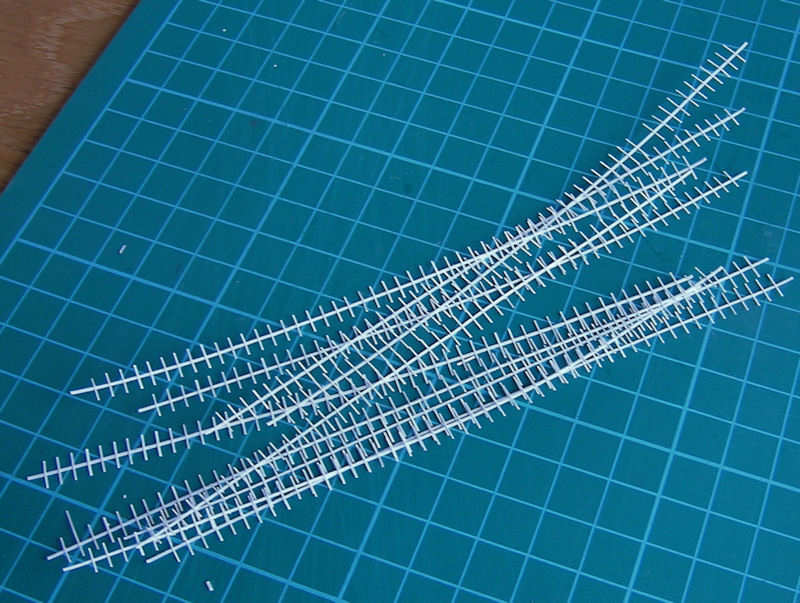
This is the gluing jig. Lots of plastic strip to help me with aligning all the parts for the cable.

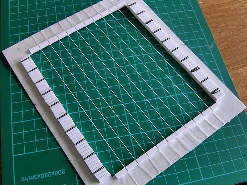
Here ten new strips of degaussing cable are taped to the jig.

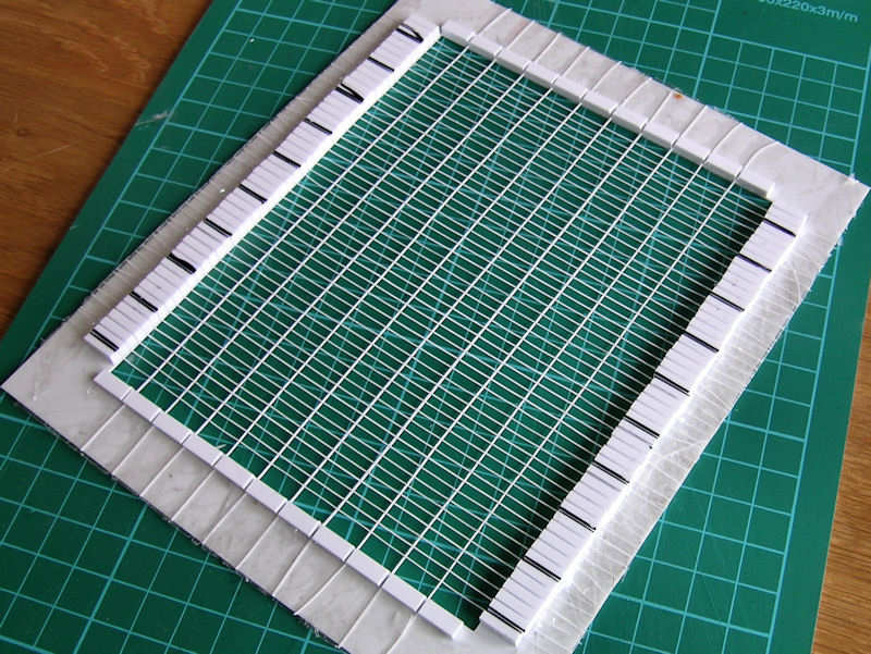
And here are, err, lots of smaller strips taped to the mould as well. They have already been glued. I tried a few types of glue, some gave a very brittle bond.

The smaller strips were made from 0.13mm Evergreen sheet, that is, very very thin. I marked the sheet with a red marker before cutting, so I knew which side should have been up. I also added the line to the other side, so that you can avoid glueing the strip without it being rotated along its longitudinal axis. Pretty difficult to see if lt goes well with all these strips so a bit of color helps.

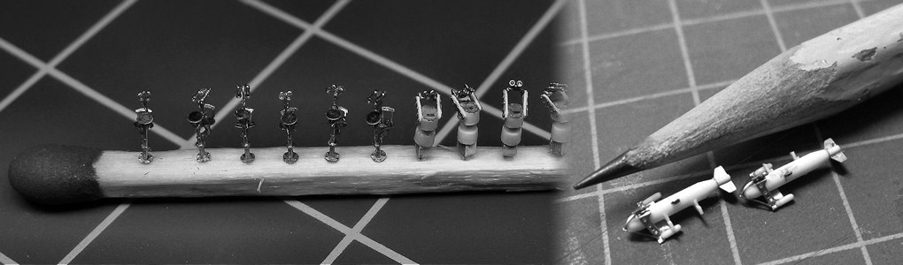
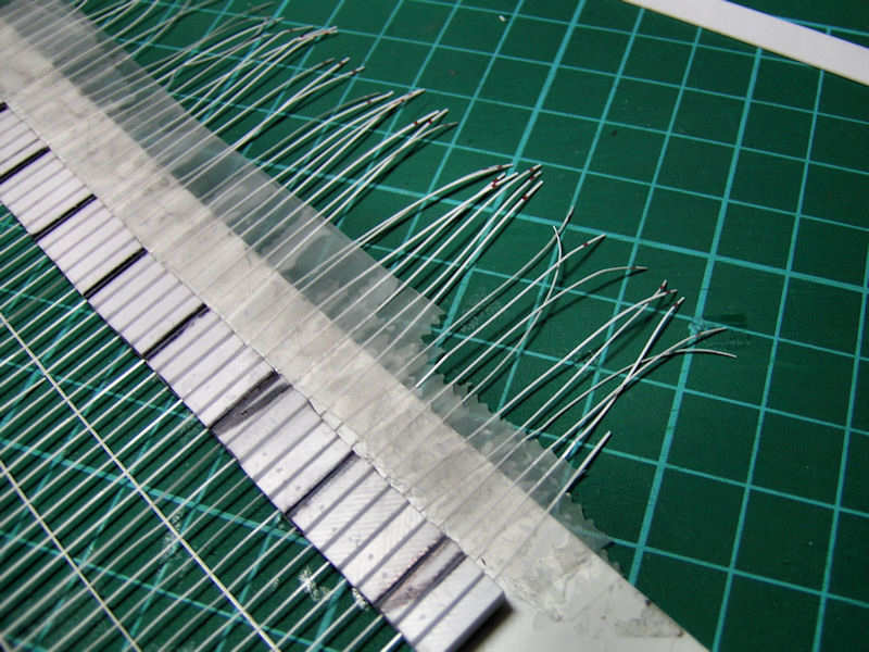
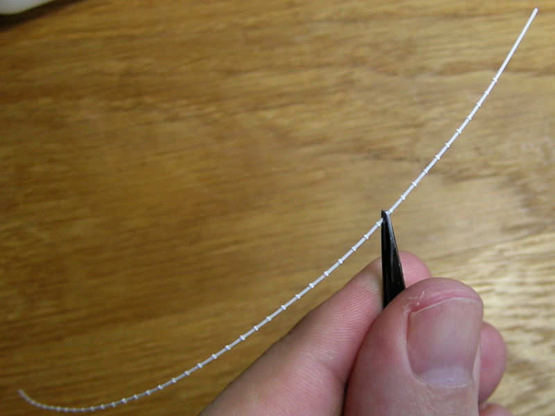
Once all the strips are glued in place, I cut the main parts loose.

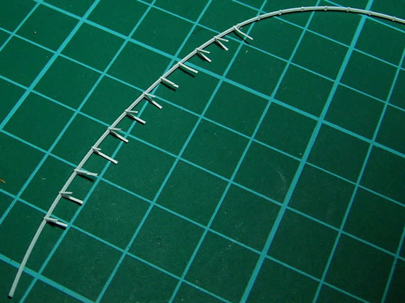
I used two tweezers to fold all the small strips: one for holding it at the junction, the other for folding. At this point, I started to loose a lot of strips (breaking or coming loose). Next, the excess strip was trimmed by pressing it down with a ruler just at the junction and then giving it a quick cut with a new and sharp blade.

Then it was sanded down and repaired when necessary. If the reparation was too much work, I just cut out a section.

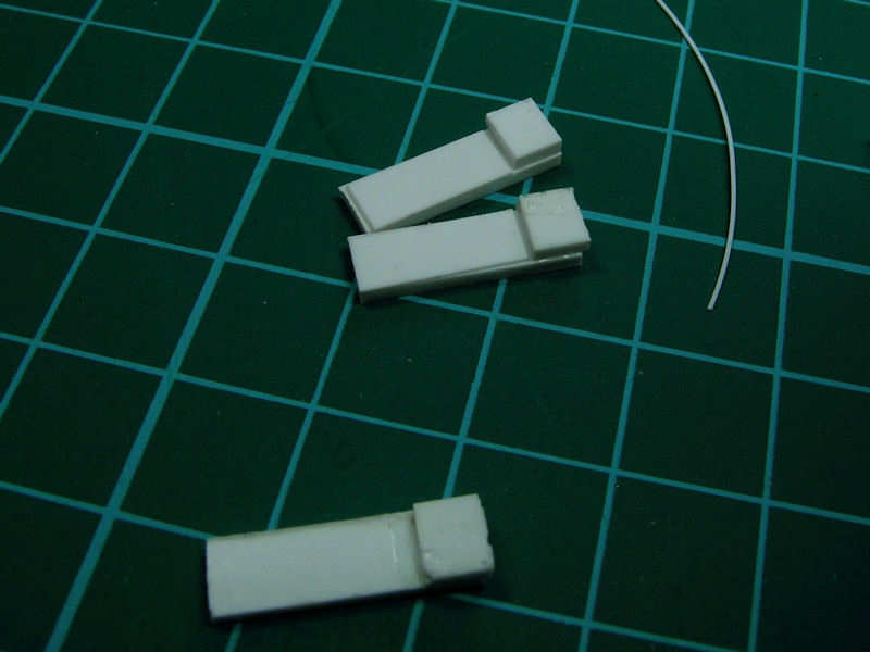
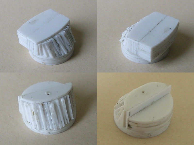
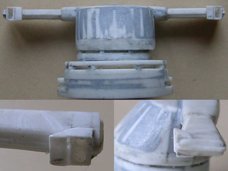
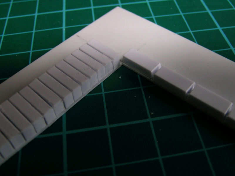
Before adding the degaussing cable to the model, I first had to add a small ridge on the exact side of the deck. These parts were very helpful in clamping a strip at that exact edge before fixing it with glue.

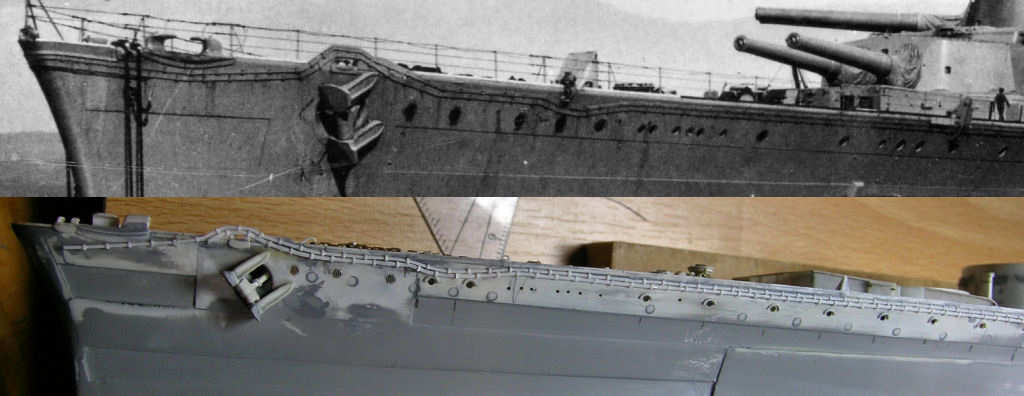
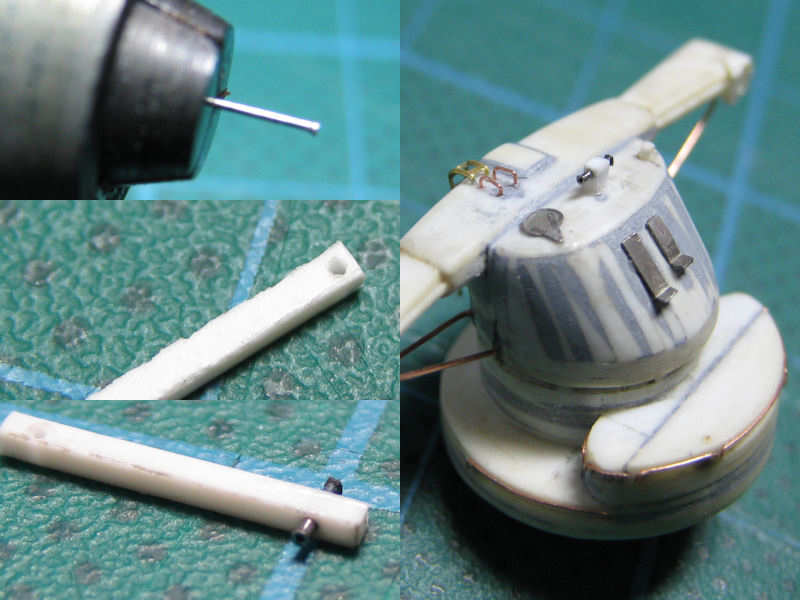
Hmm, that looks like the real thing, much better than etched cable to my surprise. Note how sloppy the real cable is and that the upper cable is slightly thinner than the other. And please don’t note that the portholes aren’t really where they should be. I’m not going to fix that…

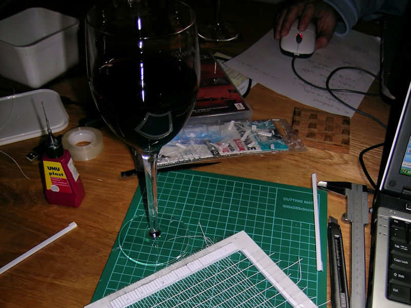
I only had 7 sets to build, so doing it while being drunk alleviates the effort. I had all the cable I needed, but left one set on the table and I have cats. Guess what happened? I’d never thought they would do that…

Main Rangefinders

This post was updated 16th of November 2008

These two objects are HMS Hood’s main rangefinders. One is situated on top of the conning tower, the other one on top of the spotting top. The parts are built up from simple circle segments.

The conning tower’s range finder still has its stereoscopic rangefinder which I built with the viewports open, just as is possible for the rangefinders of the main armament (which I kept close).

The top rangefinder houses the radar antenna for the Type 284 Gunnery Radar. There aren’t many good pictures of the frame of the radar which is a guestimate, but there is an excellent drawing in Campbell’s “Naval weapons of world war II” and a few pics of other ships carrying the same antenna. It’s much more solid than all the etched parts.

Note the configuration of the rear of the rangefinder, which doesn’t have the typical box shape added to it as found on all drawings and all but the latest models. Yours truly found out, from careful observation, that the roof of the rangefinder was locally heightened and that the box shape followed from an optical illusion, probably caused the small ladder. Having the latest photographic finds on the official HMS Hood site helped, of course. A few custom-etched parts were fitted later, a few hatches and so forth.

A small detail was added later to the forward rangefinder make from tube. The steel tube was first heated and then pressed into shape with a pointed object. Two of these tubes were trimmed to size and inserted into a plastic strip.

Main Mast, part II

The main crane derrick is operated from a platform at the base of the main mast. Two large winches are below the boat deck in the boat hoist compartment. Two cables run through pipes in the deck to a series of pulleys at the top of the tripod. One cable goes through the lower pulley and a pulley in the end of the main crane derrick, hoisting the boats on and off board, the other cable goes back and forth five times from the middle single pulley and two double pulleys—one at the top position on the main mast and one at the crane derrick’s end—setting the main derrick elevation.

The drawing in the Anatomy of the Ship series isn’t very accurately depicting the construction of the pulleys or the correct alignment along the main mast. The new position was determined using a series of pictures from this particular area. I started by adding the lower part of the frame of each pully, with a few difficult-to-cut parts. A series of supports are added to the frames, but as the wiring runs through these supports to the boat hoist compartment, and a double set of these supports is seen on the photographs.

The pulleys are an etched part plus the pulley themselves, made from 0.13mm Evergreen styrene. The pulleys rotate along an axis, but the wire as to be able to run downward with the derrick swayed to the side of the ship. I don’t know if the wiring runs through the pulley support, but it seems a logical approach. These supports were later replaced by steel tubing.

All pulleys in place. Note that the pulleys can swivel, following the position of the main derrick. The wiring, when the model is rigged, can still go around the pulley and through the supports. Not that I plan to have a fully operational 1/350 main crane, but it does allow for the use of only two wires to rig the entire crane (as in the real thing) and for alinging the lower pulleys toward the end of the main crane. In the outboard position, the pulleys are at an odd angle but that won’t be visible with the derrick in the stowed position.

mainmast_081

Copyright © 2026 On The Slipway

Theme by Anders NorenUp ↑