Author: efoeth

Secondary Guns, part I

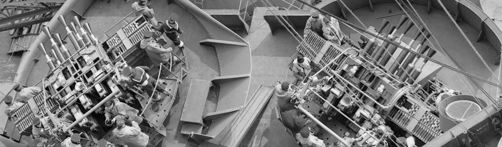
HMS Hood carried 7 Mk XVII High Angle/Low Angle Twin 4″Guns. The first four were added in 1937 and three more in 1940. These guns are open mounts with a gun shield. So, all the detail on the interior remains fully visible. I started working on new shields soon after I received the kit by White Ensign Models. Their shields were not etched but cast and are somewhat on the clunky side.

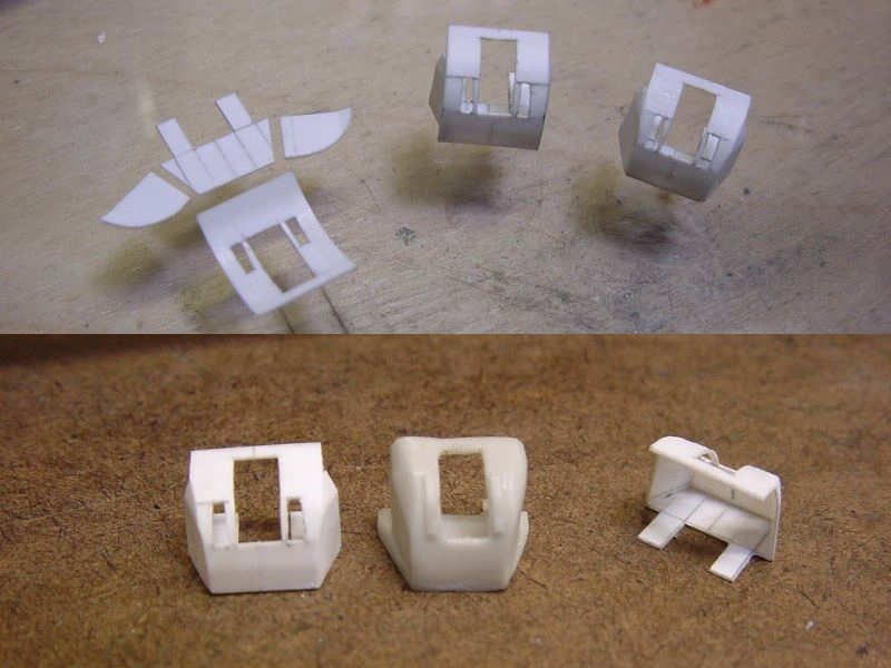
Ah, a very early attempt at building the shields (Actually, this is a result of the second set of seven shields). These parts are made up from individual sheets. It takes some cutting and slicing and a good deal of pencil work to prepare the parts which is quite difficult to do several times in a row. The problem with these parts is that both the tumble-home of the side panels and the curvature of the front panel exerted a little bit of stress on the parts. It’s not as if you could see the cracks developing before your eyes, but the height of the shields varied too much from gun to gun. Also, the parts aren’t very strong and I spent too much time puttying and repairing them. Still, they look much finer than the part by WEM.

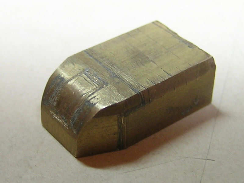
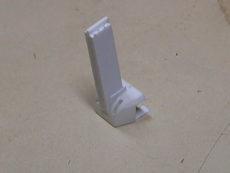
So, I decided to vacuum form the parts. This required a nice template I made from brass. Fortunately I had access to a small milling machine. This is the template after I already finished all the parts, so it shows some wear from cutting.

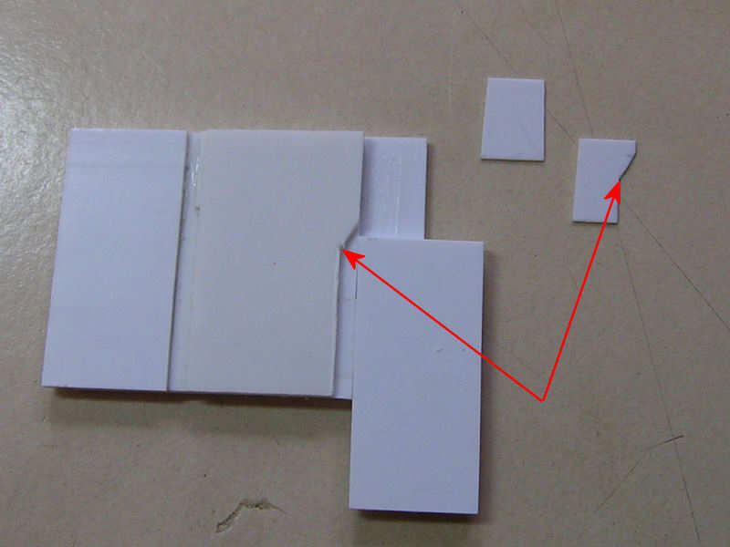
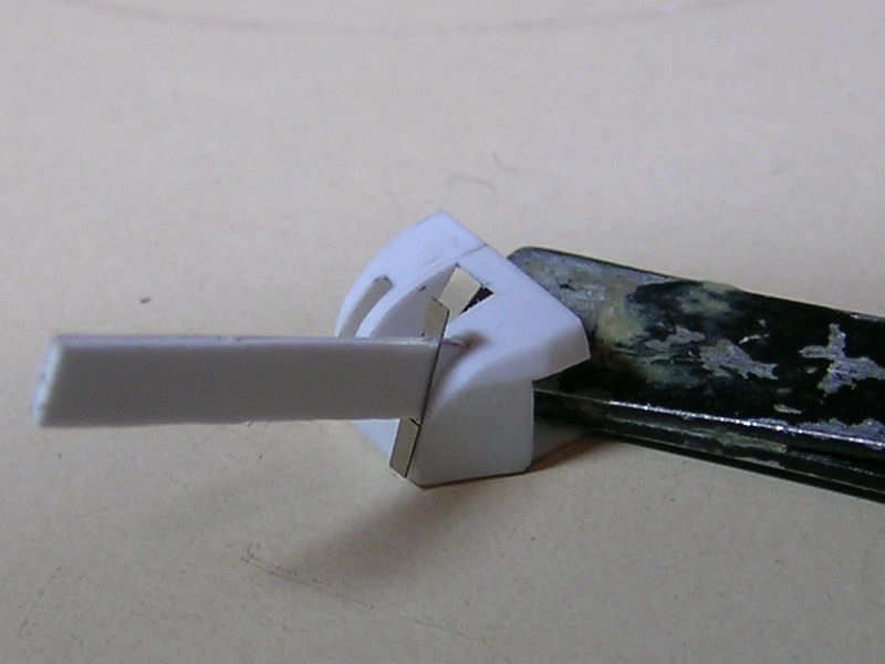
After the vacuum forming, resulting in several failed attempts, I made a series of parts to act as cutting templates. With these templates I was able to trim the parts to size with some consistency. I took my time building these cutting templates, as you can see from the above picture. I used a very fine tip X-acto knife to first scribe-in the first cut. Then I removed the part from the template and carved away.

A top view of the same sequence.

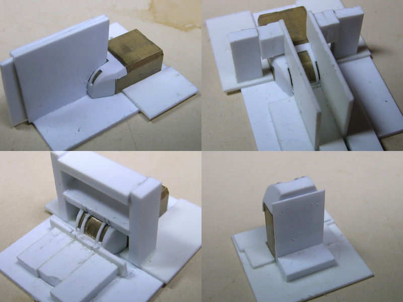
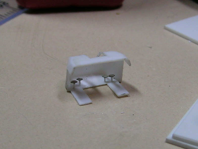
The slots in the front of the shield required a series of cutting templates; two cutting templates for the opening for the guns and the view ports, one for the horizontal lines (note that there are subtle height differences) and one for the position of the chairs. These templates were a bit tricky to align nicely as you want to keep the thickness spacing between the view ports even and small deviations show. Getting them right cost me a few more shields. Ah well.

Another cutting template, this time to trim the two internal bulkheads to size. Building all these templates takes time, but you don’t have to spend hours cutting the parts to size, deciding which ones to keep and ditching the remainder. The right side has a small indentation and the left side is angled inward 4 degrees. When dealing with two of these operations on either side with some chance of failure, templates to the rescue!

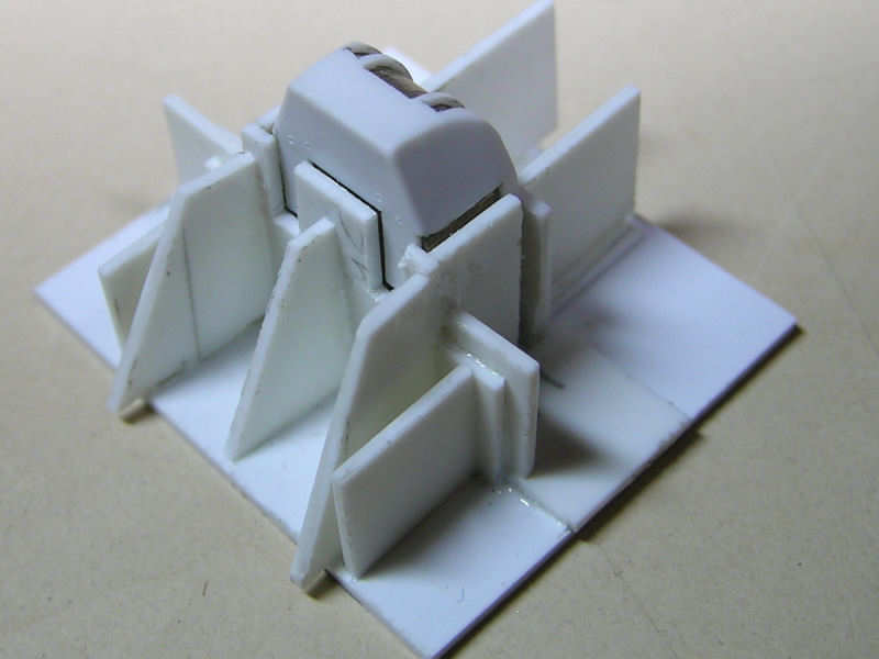
Here you can see the center bulkheads being fitted. I used a small spacer to keep the parts in the right position and angle during gluing. The bulkheads were cut to size and sanded flush with the shield.

Fitting the custom-etched hatches for the view port. Again, using a small spacer helps a lot in aligning the part correctly. Note how well the inner bulkhead tapers exactly toward the top of the gun shield

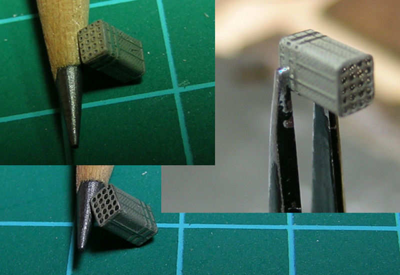
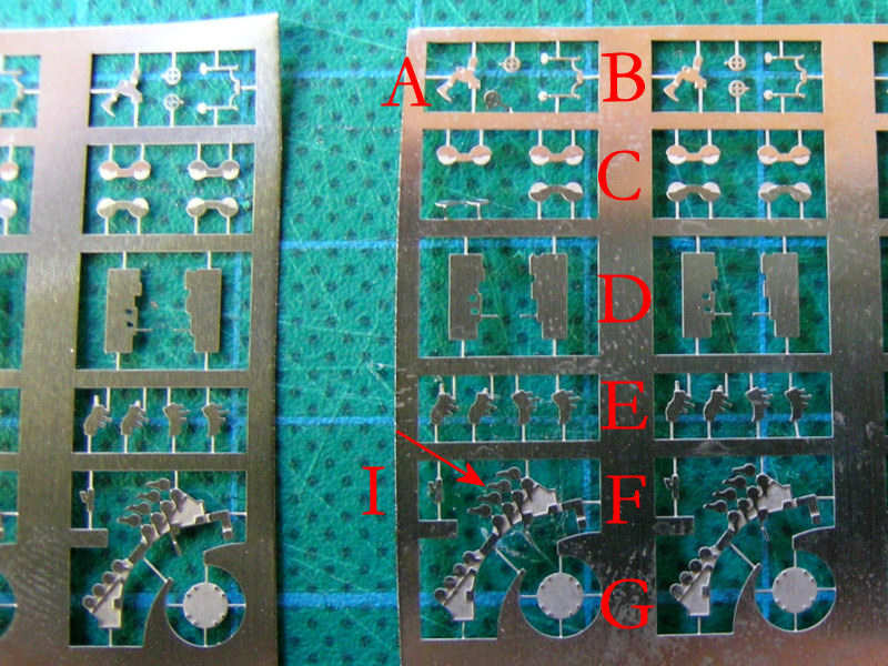
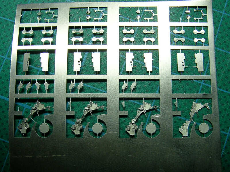
Most of the detail on the inside of the gun mount is made from custom-etched parts, including a lot of seats. Here the use to steel for the etched parts appeared to be a bad choice. After folding, the material had a tendency to break, unlike the more malleable brass (note to self).

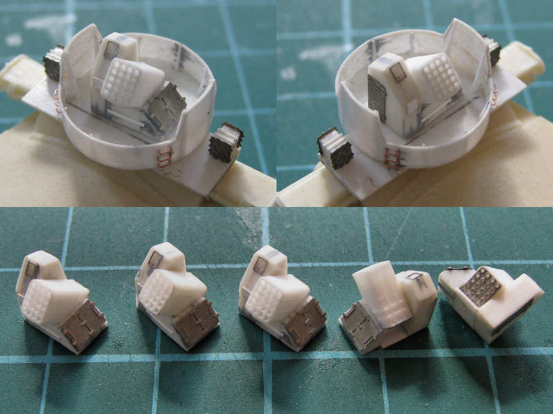
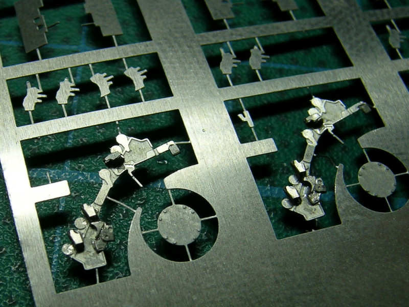
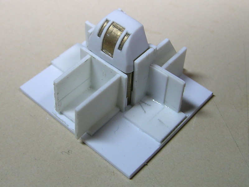
This is just a small test to see if it were possible at all to place the seats in the shield with some accuracy. Apparently, it is, even though the seats are at odd angles. Can you see that the chairs are slightly misaligned? Neither can I, but the inner bulkheads were in the way for the #3 seat (from left to right). I suppose this is a small error in the cutting templates.

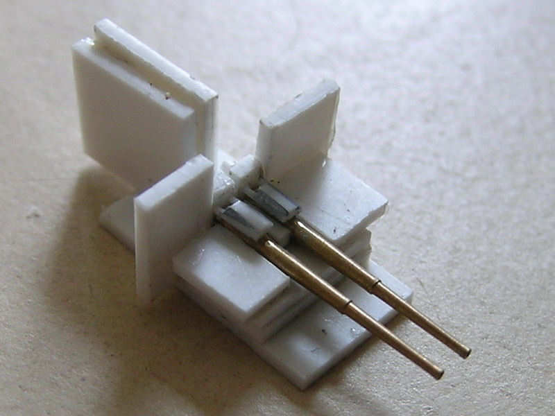
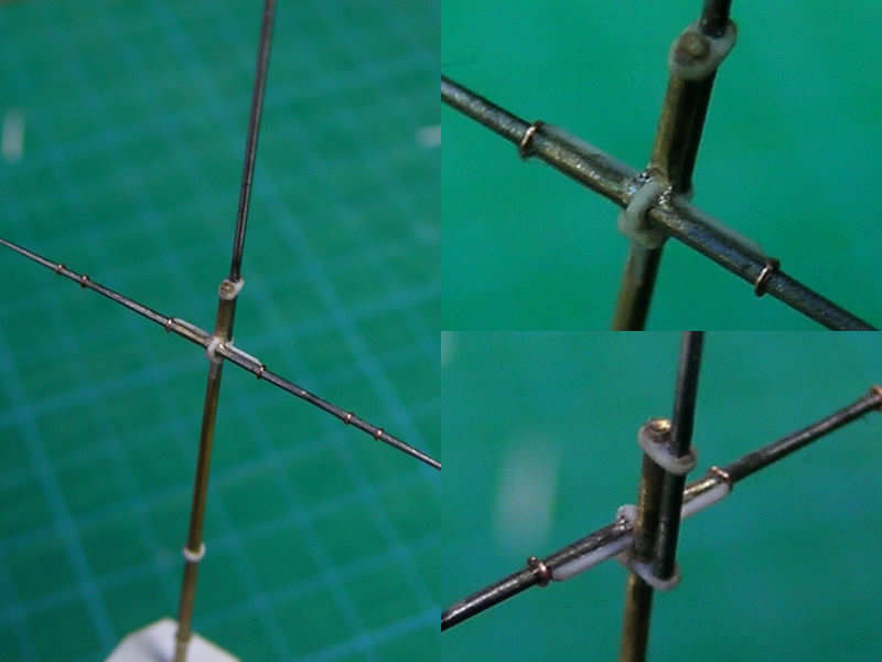
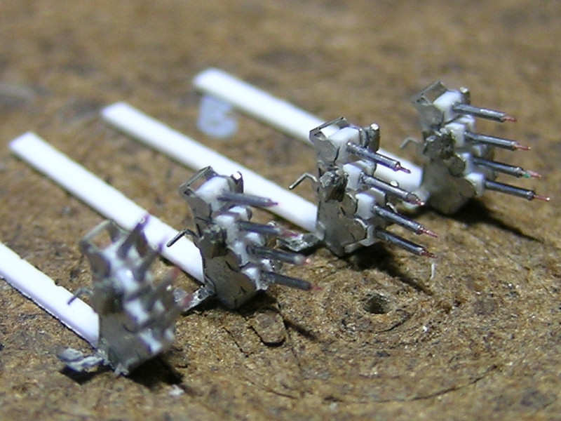
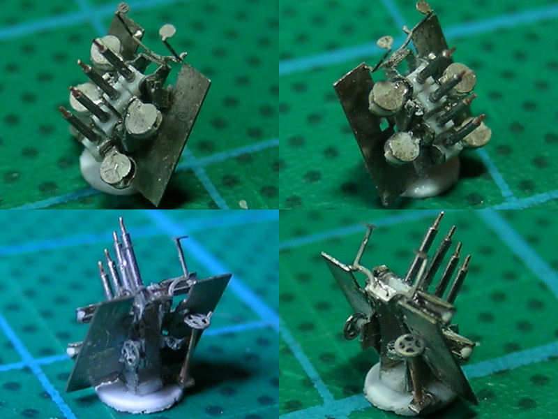
Here are the guns themselves are being glued together in yet another template. The guns were custom-order work by Steve Nuttall.

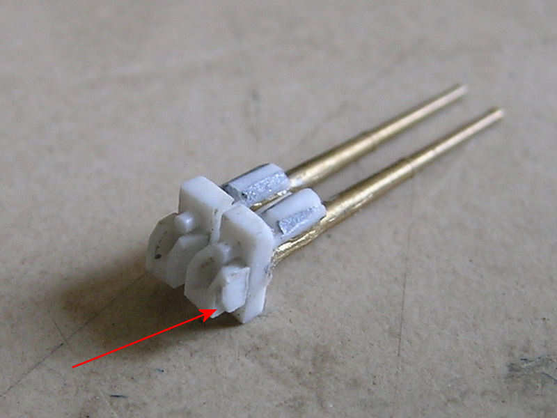
There’s a bit of detail on the breeches as well. Note the cute detail at the end of the red pointy thing.

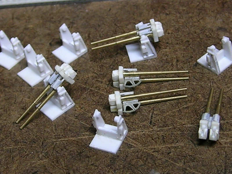
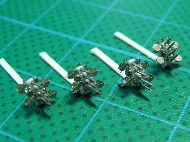
All guns and their trunnions, in a dry-fit. I got a bit carried away with the etching, so the elevation gear is visible. I doubt it is visible on the final model, but just having it on this very photograph was worth the effort. Well, not really, but I was experimenting with the etching, finding out what is possible and what isn’t. The part worked out really well.

Here the guns are bring glued to the trunnion with a template.

Main Mast, part I

HMS Hood carried a typical tripod main mast, with the topmast fastened with stays from the star fish. Several modifications were performed on the mast, including the addition of a radar set of which no drawing exist how this was actually done. The main mast is constructed from styrene and the top mast is a brass mast from modellmarine, made by Burkhardt Masch. I choose a mast with the correct lower diameter and taper, cut to length later.

Here you can see the tripod under construction. I choose to do this ‘in situ’, in order to have the tripod legs fit in their emplacements in the deck part and simultaneously have the mast completely up right. A small mould (tube) was used to keep the mast up. The small platform was cut at least 15 times before I had one with the right shape, with the small strip around the main mast of a constant thickness. That strip broke often all the time during drilling.

is a diesel exhaust pipe connected to the port side tripod leg. This exhaust is fitted to the tripod at three points. I first drilled in the exhaust pipe at the correct locations, taken from the best photograph I have to the mast taken f om the bridge, and then drilled-in in the tripod through the exhaust pipe. Next, I made several rings simulating the flanges keeping the individual exhaust pipes together. Of course, you can use rods and disks, but a single rod and rings is structurally more sound, especially with a few drilled-in holes. After the pipe was glued to the tripod mast, the rings were glued into place. A protective cover is fitted to the base of the exhaust pipe. My guess is that this cover is fitted in order to avoid damage when handling the admirals barge that is stowed very close to this location.

Each tripod leg is fitted with a ladder. I choose to use ladders by Aber, which I considered the best ladders available. They need to be folded, which is very tricky for longs lengths of ladder, but they can be directly glued to a bulkhead without additional supports and drilling in that usually spoils the fine feel of the etched part. Note the odd curve in the ladder as it approached the lower platfrom below the main starfish. I also added a cover to the diesel exhaust pipe, estimated dimensions from the photograph at right.

A nice detail shot of the main mast below the yet-to-be-fitted star fish. A small ladder runs from the upper platform the star fish. The main topmast housing is fitted to the bottom of the topmast. There are several nice drawings, but none to scale. This part will require more detail. A small metal tube is seen sticking out of the rear of the mast where the tripod legs meet. I have no idea what it is and it isn’t on any of the drawings, except vaguely on a few photographs.

A nice close-up of the topmast and wireless yard. Drawings of this yard are much better in Anatomy of the Ship: Warspite, by Ross Watton, including how the yard was fastened to the topmast. I like this detail, I haven’t seen it before on 1:350 models. The yard arm was hard-soldered to the topmast. Normal soldering resulted in a very weak bond and I didn’t like the prospect of gluing. With these scratchbuilding projects, the chances of handling damage are must greater than with kits, so I wanted a strong bond. I bought a Proxxon torch and started practicing hard-soldering. This is really tricky to do and more often than not I completely vaporized the brass parts. This is why the topmast and flagpole are made from steel. But even then, the solder wouldn’t flow between the two parts no matter how careful I was with adding flux and aiming the torch. I spent hours soldering wire together and in the end I just decided to stop playing around. Fortunately, the parts were soldered correctly in one attempt, with only some minor deformation in the topmast which was easy to remove. I added very small brass rings to the yard to simulate some much-needed detail. The flagpole is connected some distance from the topmast. To my surprise, the strength of the model is sufficient. Even more to my surprise, that flagpole was later removed to add the Type 279M radar antenna, which is a standard Royal Navy part. So, I snapped it off!

UP Launchers

HMS Hood carried 5 UP launchers when she was sunk (UP stands for Unrotated Projectile.). These weapons could fire 20 3inch rockets containing so-called aerial mines. These mines had a 238 gram explosive charge tethered to a parachute in the hope that an enemy pilot was polite enough to hit them. However, this actually never happened with the 60 units placed on various ships. The model is based on John Lambert’s drawing no. L/0/96, but this drawing contains one error; the sloped-back glacis plate was not in the drawing. The drawing did contain enough information to design a few etched parts so that some wonderful detail can be added.

The edges of the etched part folded around the launch tubes is not 90 degrees, but actually two 45 degree angles. Folding the part to size wasn’t very easy (I did use a cut-to-size fold mould) and the first folding attempt proved to be difficult. Using styrene as a filler and then drilling in the tubes using the front as a template didn’t work out either as I frequently drilled right through the etching so in the end I cast the part without the front etching. I hadn’t cast anything lately, so I order some CR-600 casting resin and 1-to-1 mold rubber from Micro-Mark. These products mix on a 1 to 1 basis, so you can mix by volume and avoid many casting disasters when preparing small batches. All the detail of the etched part is retained perfectly in the casting. I drilled in the launch tubes using a drill-press with a positioning table at the workshop at work. The tubes are 0.5mm with a spacing of 0.6mm, so that’s only 0.1mm between the ‘tubes’. Small errors show up immediately if you’re off by the slightest amount.

I forgot to cast a block to hold on to the part when using the drill press and I also lost quite a few castings due to errors in drilling or handling. I guess I cast and drilled in over thirty parts before ending up with five acceptable parts.

Here is one model protected by splinter shields atop B-turret. A door is present on the armoured operators cabinet, including the sighting window. A hatch is present on the other side of the model, probably an access hatch to the traversing mechanism. An etched part is added to the bottom of the launch tubes (not on the pic). The ammo boxes are based on photographs of HMS Hood.

Vickers Quad Machine Guns

HMS Hood carries four quad 0.5 inch machine guns. Rather ineffective and antiquated weapons I’d guess. I designed the etched parts a year or two back, and I forgot how I got carried away drawing these parts on a large computer screen using John Lambert’s excellent drawing. When I saw the final etching, I wondered if I hadn’t perhaps gone little too far. A test assembly didn’t really work out, some etched parts were just too small to handle. The final assembly worked out far better, although I spent as much time folding and gluing the parts as I did scraping away excess glue. Not an easy task, as this part is very weak and doesn’t tolerate much, if anything.

This is the original set of etched parts. Visible are the elevation gear (A), the elevation and traversing hand wheels and open sights (B), the ammunition drums (C), the bullet proof shields (D), some construction to collect or eject spent casings (E), the main part (F), the base plate (G), and some part which I forgot goes where (I). The indicated detail of F was supposed to be folded onto F, but most parts suffered some wear and broke off during folding. I added them by hand, but it was really difficult to spot the difference. In the end, I cut them all off. Unfortunately, part E was counting on the added 0.2mm thickness, as it partially overlaps parts A, so parts A were trimmed.

Parts E are very small, and it was impossible to keep them apart during the trial fittings. But, dry fitting went quite well, so I decided to keep the parts. Here you can see them glued onto the main body. With such small parts, you really need something to hold on to, so keeping the parts in the fret isn’t such a bad idea.

A close up with the elevation gear and spent casings ejectors (?) added. Note the detail in the main body, which will later be swamped by detail and superglue. The smallest lines are only 0.1mm thick, the thinnest allowed by etching 0.1mm thick plates.

Here you can see the guns under construction. The barrels are made from Scale Caliber tubing, purchased from www.cammett.co.uk . It’s the finest tubing they sell. A small brass wire is added to be the barrel. A small styrene block with a tiny hole keeps the barrels together. The final assembly shows some sloppy gluing from gun to gun, I’m not too happy about it. But, I doubt it will be visible on the final model. I decided to have one gun at a high elevation, so people can notice it’s scratchbuilt and not some standard part.

Two close-ups of the finished part. Here you can see that the ammunition drums where made with a small arc, not half a disk. The hand wheels and sights are added as well. Argh! Notice that wheel being misaligned! Hmm, the ammo druks aren’t glued properly either. Also notice that the gun is mounted on a styrene disk, aligning the part on the etched base didn’t work out at all.

Now with the ammo cases fitted. That is really some interesting fitting and aligning… Note that the ammo cases are all aligned with the barrels, particularly well noticeable with the high-elevation variant (which was the point in the first place).

All guns on a small 1 Euro coin. It’s easy to spot small inconsistencies on the photographs, but these guns are really very small as you can see. They are about 5mm/0.2″ tall.

This was a very interesting exercise and taught me a thing or two about designing my own etched parts. The ammo drums where supposed to be glued exactly into place, but I forgot to add some markers to align them. Some parts just broke off during folding and handling (and keep on doing that). Anyway, the results look satisfying and I think this is the most detailed Vickers quad 0.5 inch in 1/350 scale. I feel comfortable tackling 30 triple 25mm guns in the future…

Copyright © 2026 On The Slipway

Theme by Anders NorenUp ↑