
The parts of the bridge and fore bridge were already quite finished, until John Roberts posted the sketch below on the official HMS Hood site.
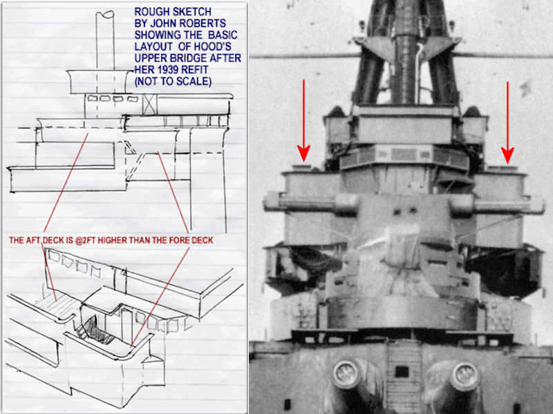
This layout, with a split level, is different from the single (extended) level in the Anatomy of the Ship series (Drawing E3/5, p86) . Two windshields are visible at the right image (arrows) that support the split-level layout. Note that the right windshield is a bit broader. I suppose this part of the shield can be swung to the side to allow access from the lower platform. The UP-launchers on the boat deck can be similarly accesses by opening the splinter shields. Note the railing at the sides of the air-defense platform (top of the image) below the canvas-wrapped equipment (inside of the arrows). These railings run wider than the roof of the fore bridge and forward position of the air-defense platform. If you look closely, you can see a ladder between the railing and the closed wind shield. The new drawing by Roberts seems to work out quite well with the few photographs of this part of HMS Hood.
The left side of the image shows the admiral’s bridge. The right side is a top view of the new layout. The width of the wind shields is taken from head-on photograph.
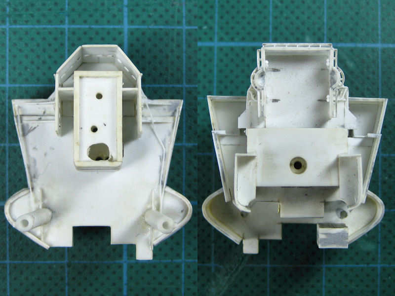
As the bridge part was already completed, it needed to be modified for the new layout. The left image shows the inserts I made for the lower half of the split level. This level is quite low, too low for any person to be standing around it. I made this part solid. I have no references whatsoever, but at least it gives the model some support. The right image shows the upper half of the split level. A part with an opening for a ladder according to the old layout was first truncated, then the platform was extended. Note that the bridge part consists of two parts that fit tightly so that the entire bridge can be painted more easily.
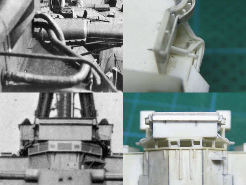
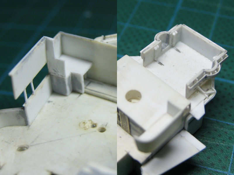
A series of voice pipes runs from the air-defense platform. I don’t know where they end up in the platform, nor do I know where the go except for the ones on the photographs. Note the railing in the top left image, indicating the platform on either side of the air-defense position is as shown top right; with a small 45-degree angle. The bottom part of the image shows the voice pipes in a forward shot and the model. Seems to be a good fit. The damage to the part being dropped to the floor is already repaired! These voice pipes took about 3 hours to add.
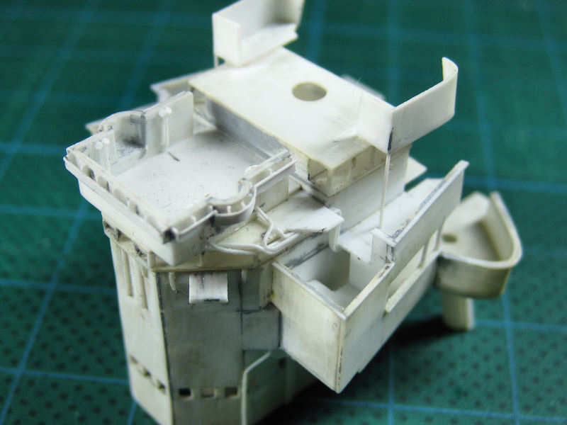
The entire bridge and fore bridge as a dry fit. From the photographs it is clear the voice pipes of the air-defense platform run backward, but I can’t see where the are going. All spotting-top voice pipes run toward the tripod, so I decided that all these voice pipes run down under the aft half of the split level toward the tripod legs. The only problem is that they are now partly blocking the door to the compass platform, but I guess they are a bit overscale. Note the opening for a ladder where the split level can be accessed from the admiral’s bridge and the voice pipes at the inside of the air-defense position. This area will be filled with air lookout equipment later to add some much needed detail!