Category: Armament

Pompoms, part IV

UPDATE 27/12/14

Right, my previous pompoms were just perfect if it weren’t for the corrosion of the solder (flux, probably). The parts were re-etched and the 100-part pompom is on its way. This weekend I finalized the guns themselves.

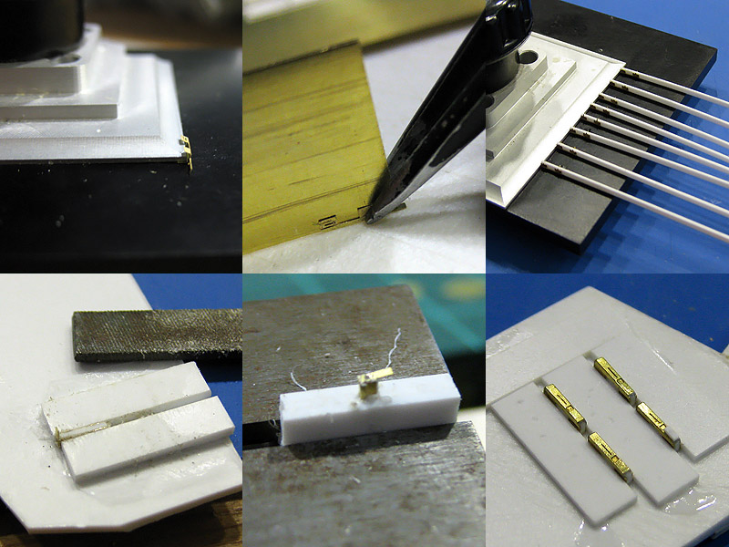
It’s very easy actually. Prefold the photoetch part with the small photoetch tool and find out it is far too crude for fine work. Find a part of brass strip to finalize the fold. Add evergreen strips that should be the right size. Be dissappointed that they are not and file all parts to the correct height using a filing jig. Replace jig from time to time. Place the part in a small jig and use the drill press to drill in the placeholder for the barrel. Be disappointed that the Proxxon drill press is unable to drill consistently, but be happy you added a photoetch part that acts as a drilling jig. Hold the part with tweezers during drilling so that the drill will not exit the part sideways. Place the guns in another jig and add a small strip on the end. File a fillet to the end of that block. Thoroughly check the gun for CA spots and clean. Add some putty to the end and sand smoothly. Find out that Tamiya putty is no longer sold in Europe and order from Singapore. Wait for the shipment while Vallejo putty disappoints you.

Because the process seems fairly repeatable I made enough guns for HMS Hood and for my next project (oh yes). Repeat the above at least: 78 times.  Loose mind, despair, find will to live and continue. Fairly straightforward scratch building.

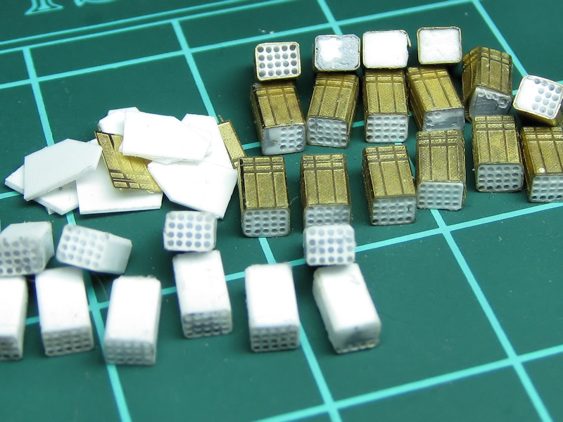
So here is half of them; these guns have a small lip to act as a spacer when added to the gun block that hasn’t been soldered yes. The barrels are on order. The mounts themselves are coming along nicely!

UPDATE 27/7/14

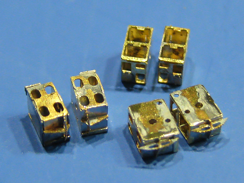
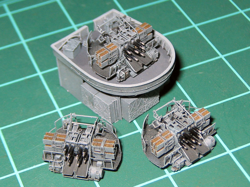
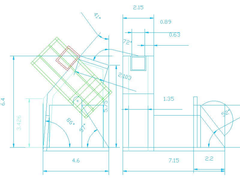
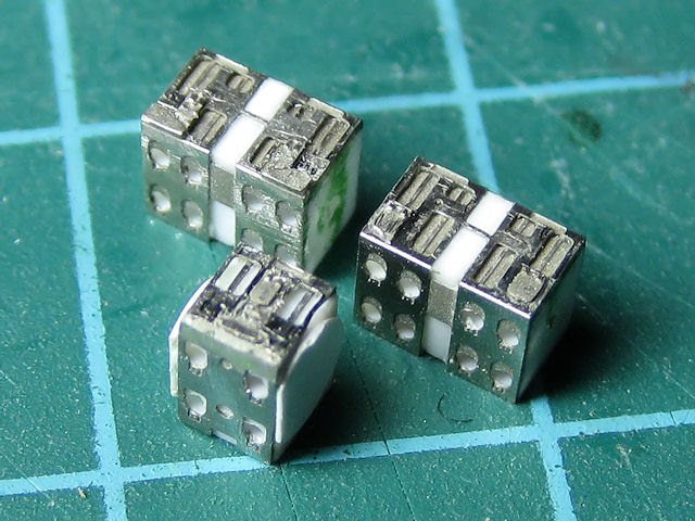
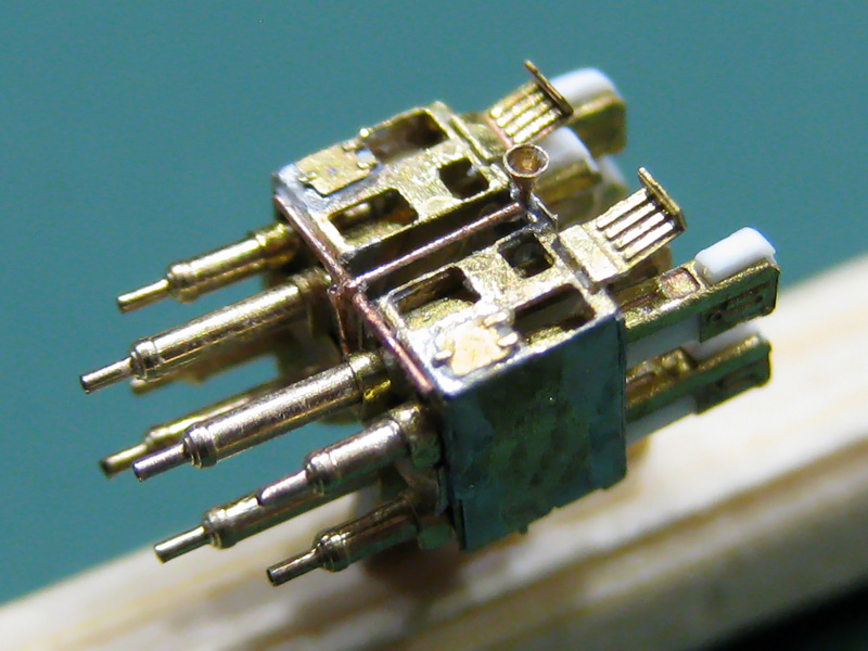
The main gun housings were soldered today with 5 etched parts for each housing: the housing itself, a center shelf that holds the upper guns, one top detail part and the two-part elevation gear parts. The housing part is sort-of self-interlocking, making it easy to hold without the risk of squeezing it with my tweezers. Soldering was quite interesting as applying heat means that some bond will release at another location (the part measures 3.3 x 2.6 x 1.9 mm only). The gun housings are supported in the center for which I made some etched part filled with styrene; the result was 0.1mm too wide and the housings ended up about 0.05mm too wide each, meaning that the sum of thee parts was 0.2mm wide and it didn’t fit. I wasted some time making the center parts fit anyway but I’ll have to add a new styrene part for that.

UPDATE 3/8/14

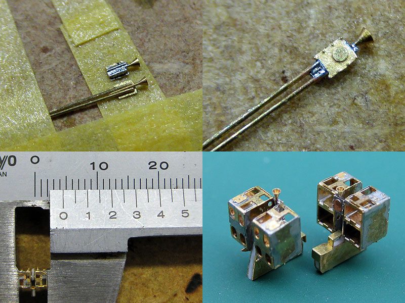
There’s a small coolant overflow cone at the end of the gun block (beautiful custom work by MASTER). I added some 0.2mm wire to either side and soldered it together so that is also works as a spacer for the two gun block halves. With some tape it’s easy to position the parts and add some solder. The first specimen was used for the general dimensions. The two wires were cut after soldering.

The gun blocks were glued to the center support after having spent 5 minutes in the ultrasonic cleaner. Fortunately, the part is now 4.5mm wide and fits the mounts. There are still a few more etched parts to keep the gun blocks together but I have to wait for the barrels to arrive. Now that some styrene is added to the model I can no longer solder and the part is delicate with superglue only until the mounts will keep the gun blocks in place.

UPDATE 10/8/14

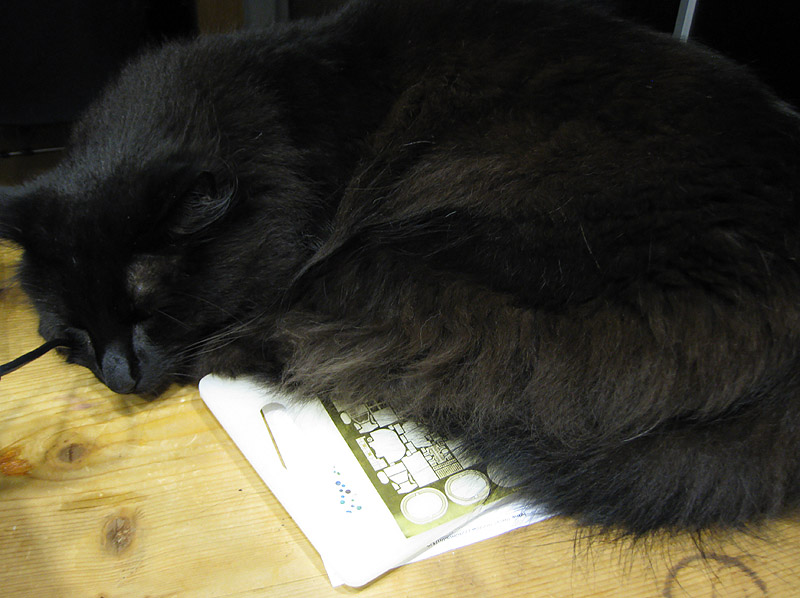
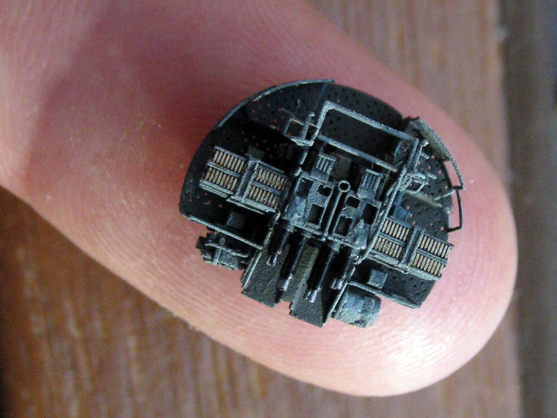
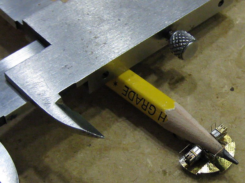
While Tiberius the Famished kept the etch set warm, I started adding the custom barrels that meanwhile arrived. You could say that the image shows how small the etch set really is, but Tiberius is a particularly large Norwegian Forest cat.

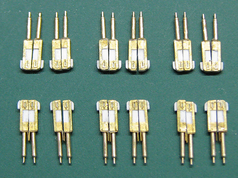
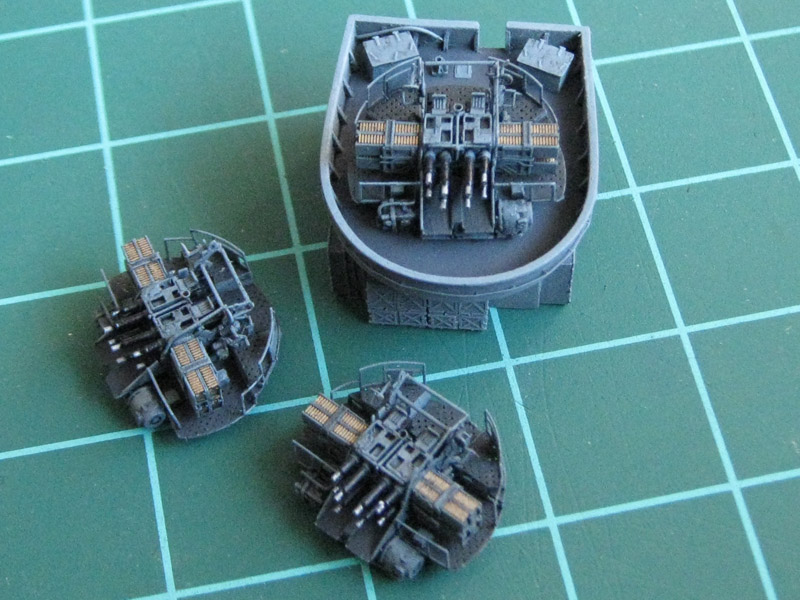
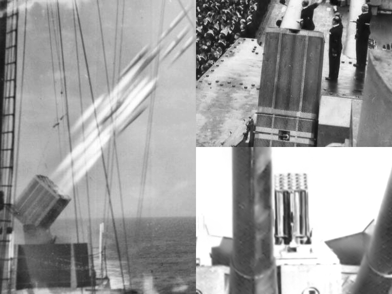
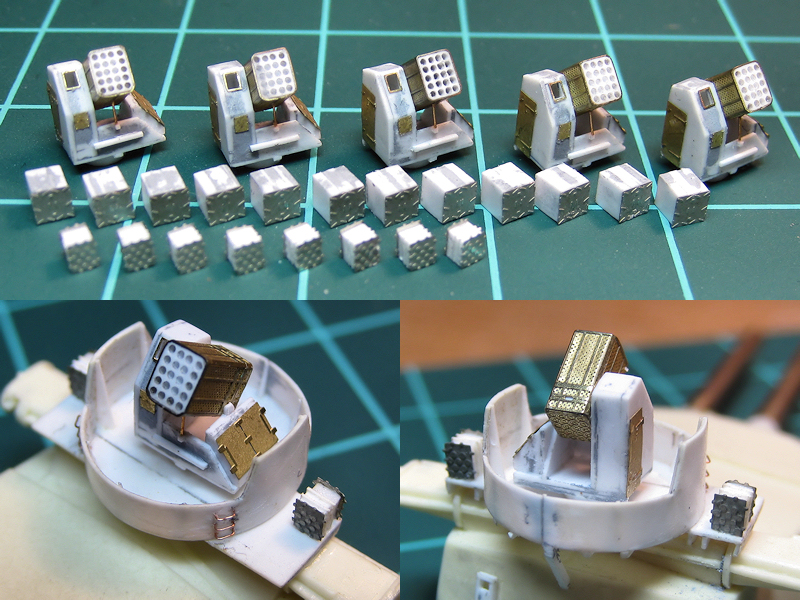
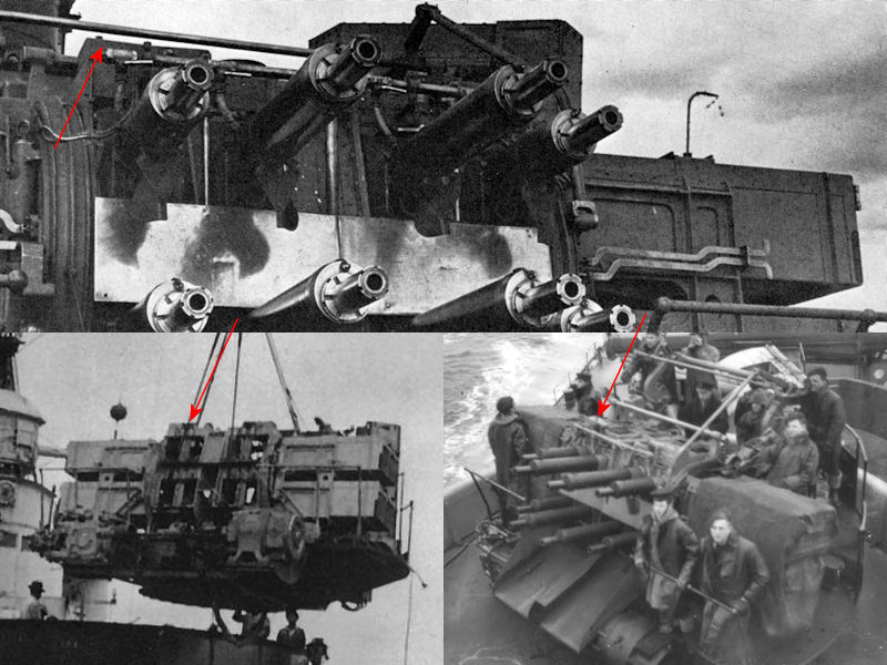
The work by Master is as good as ever and fits the tiny pompom models well. I had to do some post-drilling by hand of the styrene guns to clear all the ‘chips’. Note that the conical flash suppressor that is ever present on all pompom models is absent; HMS Hood did not yet receive the upgrade to the pompoms and the barrels are thus plain and simple. The bottom row of pompom guns have a small lip below the barrel; this is a spacer for the correct offset of the outer barrels. One gun block was finished today but another one fell apart during handling; I hope to finish the rest soon. I learned the hard way that once parts start breaking up it is a good moment to stop.

UPDATE 17/8/14

All the gun blocks are all done; the guns were inserted and final detail was added. The cooling lines to the guns are partially added; the pipes running to the barrels themselves where eventually ‘canceled’ was it was too small to do repeatedly nice. I gave the models a coat of paint. I found out that out of the four premixed colors two batches again went bad and turned into sludge. The others, same ingredients but in a different ratio, are just fine. If anyone has tips how to improve the shelf life of premixed Humbrol to more than 2 months, let me know!

UPDATE 2/9/14

One down, two to go. Soldering the sights was tricky, holding the PE part with tweezers in one hand and the soldering iron in the other… still have to add that curved bar from the portside sight to the guns but I think I’ll glue that one having spent too much time trying to solder it.

UPDATE 20/10/14

I wouldn’t want to leave the impression no progress has been made, even though most weekends have been quite busy, including a visit to the Small Scale Convention at Heiden, Germany, where the unfinished Hood was on display. There were many stunning models by the IG waterline group and the ‘German gamblers’ to study. One visitor wondered if the Lion Roar pompom set tempted me into building the rest of the ship myself? Well, it’s a bit more weird than that!

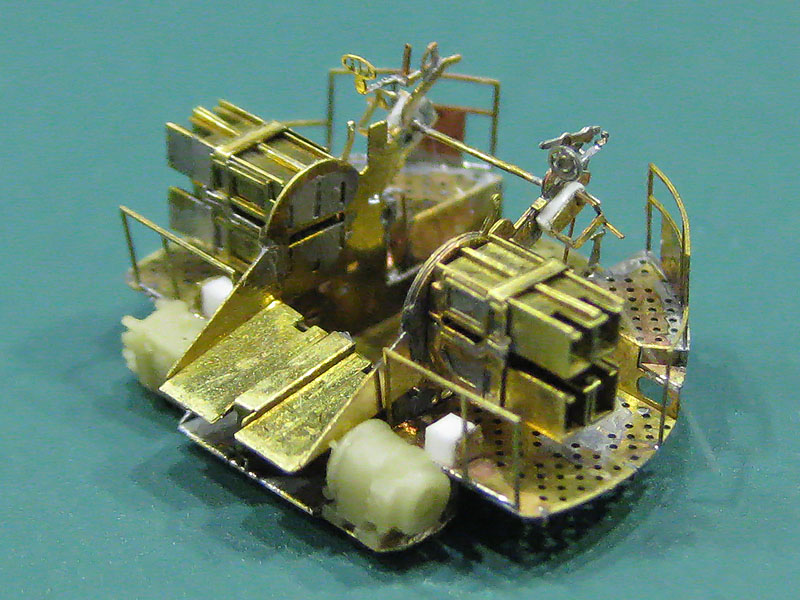
The pompoms have received some attention; here you can see one of them in my “high tech” clamping mechanism ready for some soldering of the rear railing. I have to add a few more lines of the hydraulic system and the base of the guns and then I can move on to painting.

UPDATE 27/12/14

Done! One picture with flash so they look awful, but it is snowing and light conditions plus a bad camera make bad pictures.

UP launchers, part II

My UP launchers were destroyed after receiving a coat of Vallejo primer, a primer that did not stick to the resin or the stainless steel photoetch. I designed new etched parts for the launchers and started all over.

I made a small sketch based on John Lambert’s drawing and I added a few modifications (The drawing by Lambert is based on photos, so I guess that’s fine). I thought it would be easy to repeat these models but these launch tubes were very difficult. The launch tube is a styrene core with a PE part wrapped around it. The styrene core really needs to be accurate with 0.1mm or the PE parts will come off when held in the calipers when drying or in the vise of the drill press. Then the PE part itself needs to be folded accurately. Somehow I thought it would be better if the PE part had 8 folding lines instead of 4, to capture the correct form of the launch tube with the 45-degree edges. Then you need to drill in all the tubes. I reread my previous post where I read I had to make 30 parts before I had 5 good parts. This time I didn’t no any better. I fear the Proxxon cross table and the cheap drill press isn’t any good resulting in poor reproducibility (a few hundreds of a mm will show up easily in this closely knit pattern). Also, the front of the launcher part has to be completely smooth or the drill will wander. This is why the styrene core is built up from strips but with a single flat strip glued at the end; this really helped with getting a consistent pattern. One major consumer of hobby time when using the drill press is finding a reference point, or zero. I ruin 2 or 3 parts before I find the correct position so I need something better. Trying really hard doesn’t cut it! After a while you’ll find the entire pattern lined up nicely in the center of the launcher. Two conclusions. One: I need to learn to cast properly to avoid making all these difficult parts over and over. Two: I need a proper drill press with a cross table or CNC milling machine to punch in these difficult patterns.

So here they are, the low yield of several days of trial and error. I did manage to make the gunners viewport open which is an improvement. There are also 12 large ammo lockers and 8 small ammo lockers, one set for each launcher except the one on B-turret. I do not know where they stored the large ammo locker.

And just for fun, all the parts I have made that didn’t work out!

Octuple pompoms, part III

Continuing from part II.

Because I though it would be fun, I purchased drawings of the quadrupple guns along with the Mk V and MKVIs of the octuple pompoms to make small models to be distributed by any manufacturer. If you have seen the barrels of Master from Poland, you know you are dealing with a manufacturer who’s really committed to accuracy. I asked them if I could trade a few custom barrels for the etch design and a few parts. They said yes! However, having accurate custom made barrels as tiny as a 1:350 40mm gun is great but now my models couldn’t be so awkward that only I can handle them; other people have to be able to make them as well. So, I decided to make a series of prototype guns. One set of three guns is for my own model and will be a set of no-comprise all-singing-all-dancing models. One set of three different guns will be made for Master for casting. One set of two guns will be made as a demonstration showing that all parts—etched or cast—will actually fit. I made a series of parts and the best parts were selected for casting, the worst part was for the test-fit model and the rest are for my models.

Here’s a production drawing that was sent to Master. The cooling (heating) sleeves around the guns are placed eccentrically but not on the models. A small rod will be placed inside the gun cradle master so that all guns will fit nicely. The bottom drawing shows a version of the gun with additional sleeves (Remote powered versions). Perhaps some drilling is required for the cast parts. Note that both short and long barrels are designed for the inner and outer guns.

The gun cradle started as one main part with a smaller detailed part glued to its inside. The MASTER model will be a monoblock.

The gun cradle block was drilled through using the drill press. I had to first position the drill and to then take a picture using the macrosetting of the camera to see if the drill was set properly! Perhaps I should buy a visor or magnifying lens?

Small detail parts were added to the roof of the gun cradle. I use Tamiya tape to position the part and use a 0,1mm brass wire to apply a drop of glue. The gun cradle of the quadrupple gun is seen at right.

All MASTER gun cradle parts are now complete. The parts are fitted with disks or rods to help aligning them in the main etched parts.

There are two pieces of equipment at the front of the model; an electric motor and the hydraulic pump. Here’s the production drawing for the electric motors. With these small parts, you really have to plan ahead and such CAD drawings are of great help to me.

Here are the models of the electric motors situated front left on the model. They are a combination of lathed parts and rings made with the punch & die set (I make all rings on the lathe now, the punch & die is not accurate enough). The brass wire is 0.1 mm thick.

The pump for the hydraulics is on the other side. This part is much more complex than the drive motor. A lot of pipes run from this gear to various points around the weapon. It appears to be an iron cast housing of complex shape. I made an approximation for this part. The final part isn’t really as accurate as the drawing might suggest. This part was so time consuming to make that I decided to make one and cast the rest. Among other small parts I decided to cast are two hydraulic units behind the ammo trays, bolted to the side of the main gun frame.

This is an overview of all the parts. The top left part of the image shows the hydraulic pump and drive motor situation at the front of the gun. The image top right shows the elevation drive with one of the hydraulic pumps below it, also shown bottom left. The bottom right image shows the rear of the guns protruding from the rear of the main gun housing.

These are the test-fits of the demo models. The parts are assembled a bit wobbly… I was so preoccupied with detailing the modes that I forgot that HMS Hood carried one Mk VI. The main etched part for the gun cradle is now a Mk V but the rest of the parts are not. Complaint forms can be downloaded at the IPMS main website. Anyway, the fit is fine but some parts were very difficult to align. Many of these errors were ironed out for the second design. These etched parts arrived last week.

The new design works much better. It’s made from brass so I could finally solder all parts; no glue so far. I have no experience with soldering but you learn a lot in a day. One ammo tray took hours, disassembling itself when re-adding heat; the second one was produced quite quickly. Still, these are very tricky models to make but the results should be well worth the trouble!

Octuple pompoms, part II

Continuing from part I where I showed the etch design for the new octuple pompoms. I published only the Mk V, but I was working on three models: the pompom guns in question are the octuple Mk V and Mk VI and the quad Mk VII.

The Mk V gun is the prewar version (then called the Mk M, M for multiple) first fitted to HMSs Valiant, Nelson, Rodney, Hood, Furious, Royal Sovereign and Renown. The Mk VI, fitted in 1934 and onward, is nearly the same with minor differences in the platform and gun cradle (central weapon housing). Several capital ships were fitted with one or two of either type, although a shortage of the guns meant that Renown and Valiant initially received only one. Both types were later updated to automated fire resulting in the Mk VA and Mk VIA. Guns designated with a * behind their Mark denote a weapon fitted with guns firing a shell at a higher muzzle velocity. Later versions were remote powered denoted RP10, RP11 and RP50. Most ships were fitted with a mix of versions of both Mks or remote power units. The Mk VII is the quadruple version with again many variants, e.g., the Mk VII*P being the high muzzle-velocity self-contained power mounting. The late war version of both the octuple (Mk VIA* rpxx with the aft part of the mount fully enclosed by shielding) and quad guns (Mk VII P*) are much more complicated to make and are a completely different weapon to model. Of course, John Lambert drawings has all of them but you have to stop somewhere. The differences between the Mk V and Mk VI are slight but as HMS Hood has two Mk Vs and one Mk VI (on the bandstand just behind X-turret) I wanted to have both correctly modeled. I currently do not know for sure how to distinguish between the normal and automatic (A) fire guns or high-velocity versions, but I suspect that the (conical) flash suppressor is typical for the automatic version? Most ships were upgraded to these types of barrel at some point in their life.

I have prepared a few images showing the early/mid war versions of the weapon and how to recognize them.

This is an excellent image of a Mk M or Mk V aboard HMS Rodney, taken from Man O’War 3 (1979) by Raven & Roberts. Note the small ‘hatch’ on top of the gun cradle. This is typical for the Mk V. No flash suppressors are seen on this weapon. It appears that the gun sites are already the more modern version than those on the Mk M. Note the two sailors loading the ammunition.

The Mk VIA* is the gun you’ll see on most ships, here aboard HMS Prince of Wales taken from Ensign 1 (1972) by Raven. Note the structure on top of the gun cradle is different and two ridges are visible. This weapon was fitted with flash suppressors at the end of the gun barrels. The early ships of the King George V class were delivered with these weapons, later expanded to as much as eight octuple mountings. Note that the gun sights are the sights as in most photo-etch detail sets, but that these sights do not appear on early versions of the pompoms.

This is an image of a pompom Mk VA* aboard HMS Nelson or Rodney (forgot source). Note the small hatch on the gun cradle in combination of the flash suppressors at the end of the gun barrels, so we can be sure this is a Mk V, not a Mk VI. After both Rodney and Nelson were fitted with more pompoms near their secondary battery, quarterdeck and B-turret (Mk VIA), it appears that the older Mk V weapons received new guns (or were upgraded to version *). Pictures of both battleships—and many others—after fitting the additional modern pom poms show the barrels with the flash suppressors.

This image shows Mk VIs prior to 1939 without the flash suppressors. Images of this version are a bit harder to find. Note the ridges on top of the gun cradle. The top of the image is part of a photograph taken on board HMS Ark Royal from British Battleships of World War Two (1976) by Raven & Roberts; the two lower images were taken aboard HMS Hood with permission from the official HMS Hood site. Again, the ridge on top of the gun cradle is visible. Note that the weapon was not fitted with flash suppressors at the end of the gun barrels, so those suppressors clearly do not give away the type of mounting version.

This pom pom has water cooling jackets around the barrels, indicative of it being an RSP mount. Note the splinter shielding on the aft platform of the weapon. HMSs Howe and Anson were fitted with these modern variants. This image is reproduced with permission from Maritime Quest.

I made a small list of what battleship was fitted with what type of weapon and if they were fitted with or without the flash suppressors (new barrels) so you know what gun to place on what ship. This list is based mostly on Raven & Roberts British Battleships of World War Two, one of the few references that state what weapon was fitted, though not in full detail for each ship. The list is complemented and corrected by observation of what pics I could find that clearly show the type of barrel and/or type. It’s not always clear if, for example, if HMS Valiant and HMS Queen Elizabeth retained their older pompoms after their refit, as with HMS Rodney and HMS Nelson, or received all-new units as with HMS Renown. I’ll try to keep this list updated when necessary.

LIST OF GUNS
Last update: June 2010.

*    New barrel with conical flash supressor

HMS Queen Elizabeth
1936 2x Mk VI
1941 4 x Mk VI*A
HMS Valiant
1930 1 x Mk V (starboard only)
1932 2 x Mk V
1941 4 x Mk VI*A
HMS Barham
1934 2 x Mk VI
1941 4 x Mk VI*
HMS Warspite
1934-36 1 x Mk V , 1 x Mk VI
1937 1 x Mk V , 3 x Mk VI (4 x Mk VI*?, new barrels)
Images taken in 1937 show old barrels, but new barrels in 1943. Replaced during the refit in 1942? All units replaced?
1941 1 x Mk *V , 3 x Mk V*I
HMS Malaya
??? 1 x Mk V, 1 x Mk VI
1941 1 x Mk V*, 3 x Mk VI*

HMS Hood
1931 2 x Mk M
1938 2 x Mk M, 1 x Mk VI

HMS Renown
1932 1 x Mk V (port side not fitted)
1936 1 x Mk V, 1 x Mk VI
1939 3 x Mk VI*A (all replaced)

HMS Repulse
1934 2 x Mk VI
1940 3 x Mk VI

HMS Rodney
1932/33 2 x Mk V Abreast forward side funnel
1938 2 x Mk V, 1 Mk VI*A (aft deck)

This image taken in October 1940 shows the new type of barrel aboard HMS Rodney. Image from the Imperial War Museum Collections Online Database.
1941 2 x Mk V*, 3x Mk VI* (one on aft deck) 1 Mk VII* on B-turret

HMS Nelson
1934 2 x Mk V Abreast forward side funnel
1940 3 x Mk V (one on Q-deck), + 2 x Mk VI (in place of secondary director-control tower)
1941-1942 3 x Mk V*, 2 x Mk VI* + 1 Mk VI* on B-turret (6)

HMS Resolution
1936 2 x Mk V/VI?
1941 2 x Mk V/VI* , 2 x Mk VI*I (B-turret, Q-deck)

This image of HMS Resolution from the HMS Resolution association shows new barrels for the quadruple pompoms.
HMS Revenge
1931 1 x Mk V (starboard only)
1939 1 x Mk V, 1 x Mk V/VI (type not know, probably Mk VI)
1941 1 x Mk V*, 1 x Mk V/VI*?, 2 x Mk VII* (B-turret, X-turrets)
HMS Royal Oak
1934 2 x Mk VI
HMS Royal Sovereign
1932 2 x Mk V
1942 2 x Mk V*, 2 x Mk VII* (B-turret, X-turret,)
HMS Ramillies
1934 2 x Mk VI
1941 2 x Mk VI*, 2 x Mk VII* (B-turret, X-turret)

This image from 1944 is reproduced with permission by Mick French & the HMS Ramillies Association, showing new barrels on the excentrically placed quad pompoms.

King George V class
All ships had the Mk VI or later with the new barrel
HMS King George V
1940 4 x Mk VI*
1941 5 x Mk VI*, 1 x Mk VII* (Y-turret)
1944 8 x Mk VI*
HMS Prince of Wales
1941 March 4 x Mk VI*
1941 July 5 x Mk VI*, 1 x Mk VII*

This image taken during the Atlantic Charter clearly shows that a quad pompom was fitted to HMS Prince of Wales’ Y-turret, still present on images taken as late as December 1941; she never carried an octuple pompom in this location. (courtesy of the United Nations

HMS Duke of York
6 x Mk VI*
1946 8 x Mk V*I, 6 x Mk VII*
HMS Anson
1942 6 x Mk VI* RSP?
1944 8 x Mk VI* RSP?, 4 x MK VII*
HMS Howe
1942 6 x Mk VI* RSP?
1944 8 x Mk VI* RSP?,
1945 8 x Mk VI* RSP?, 6 x Mk VII*

Copyright © 2024 On The Slipway

Theme by Anders NorenUp ↑