Category: Boats & Launches

Ship’s Boats: change log

16/03/2025


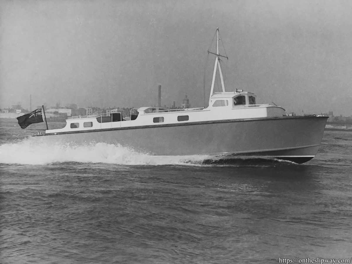
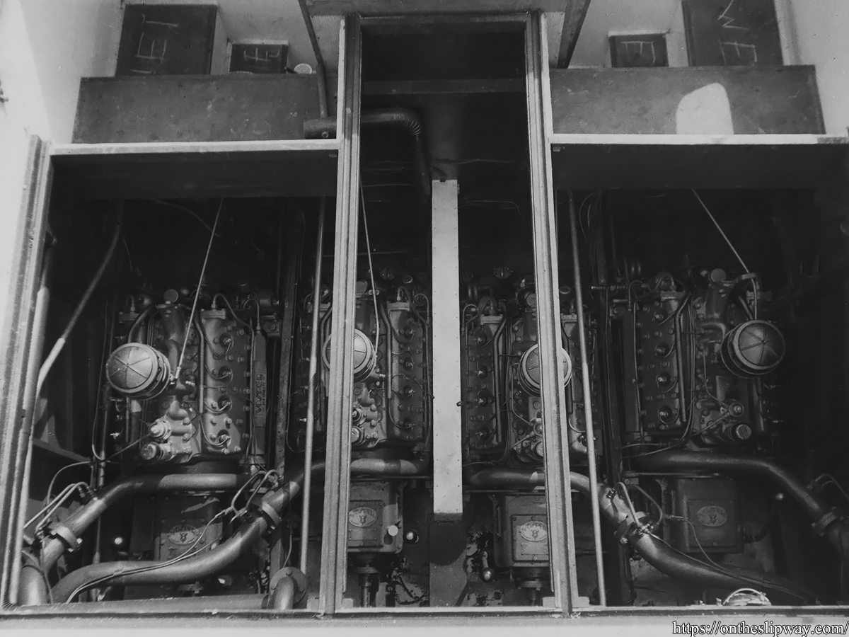
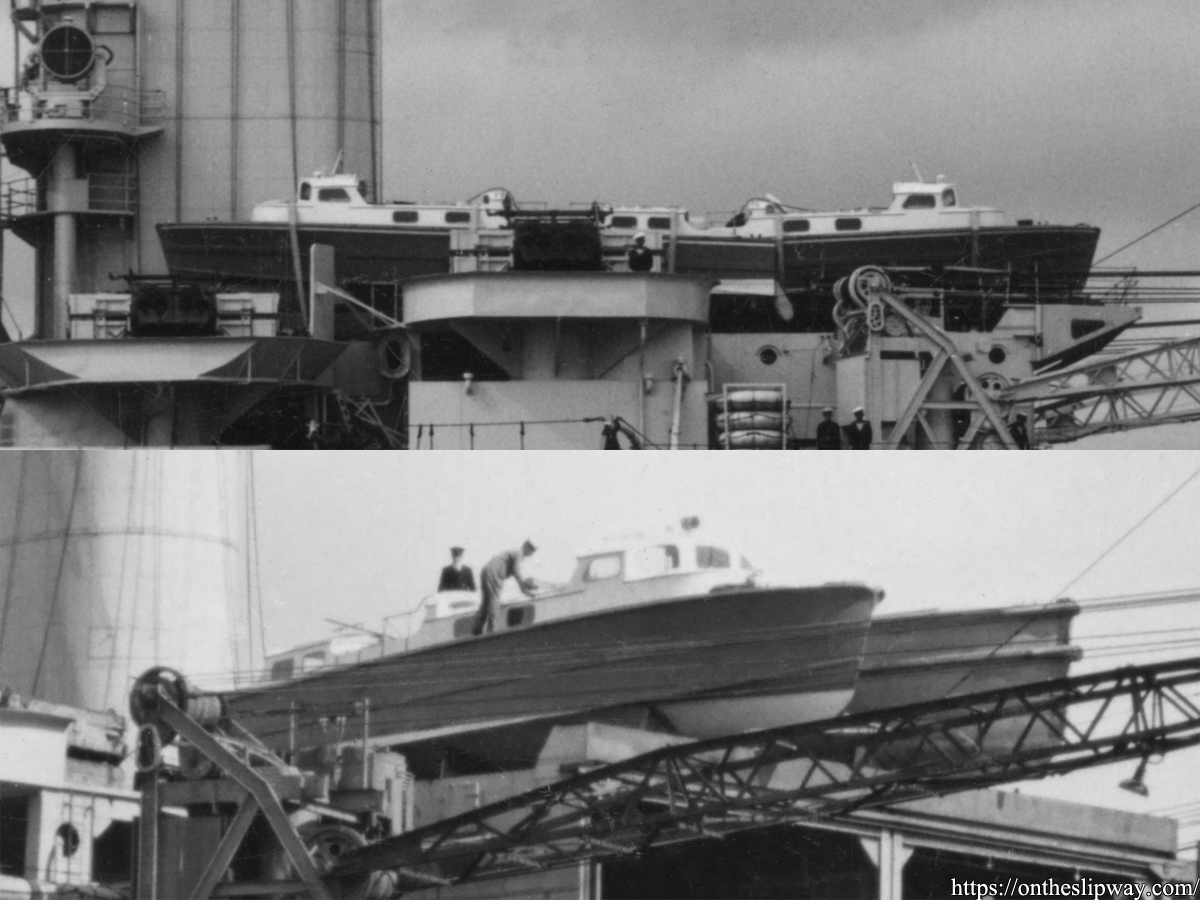
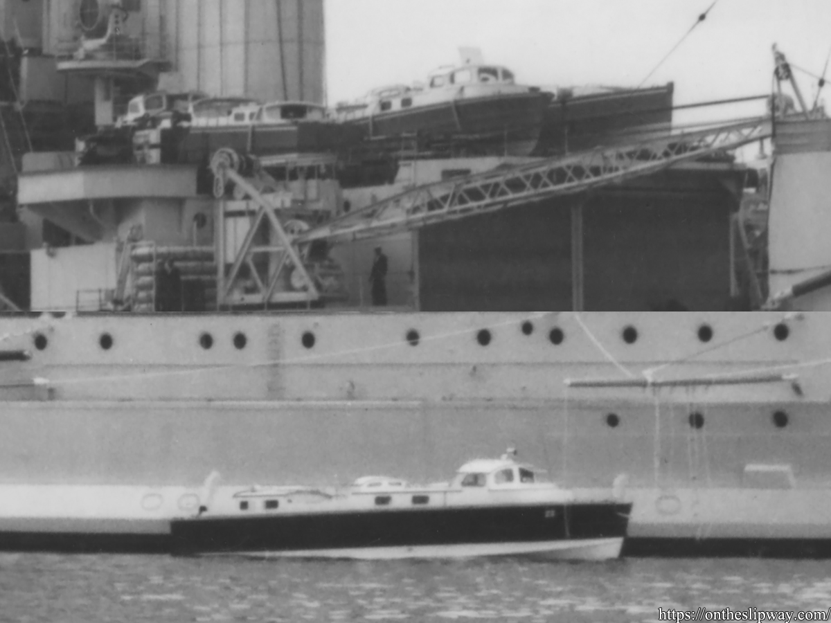
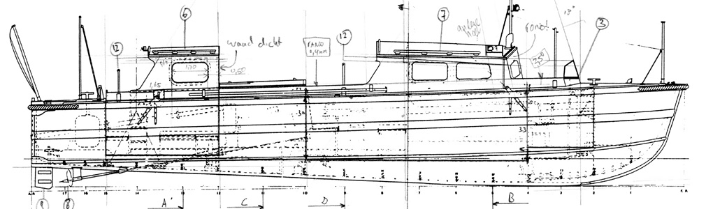
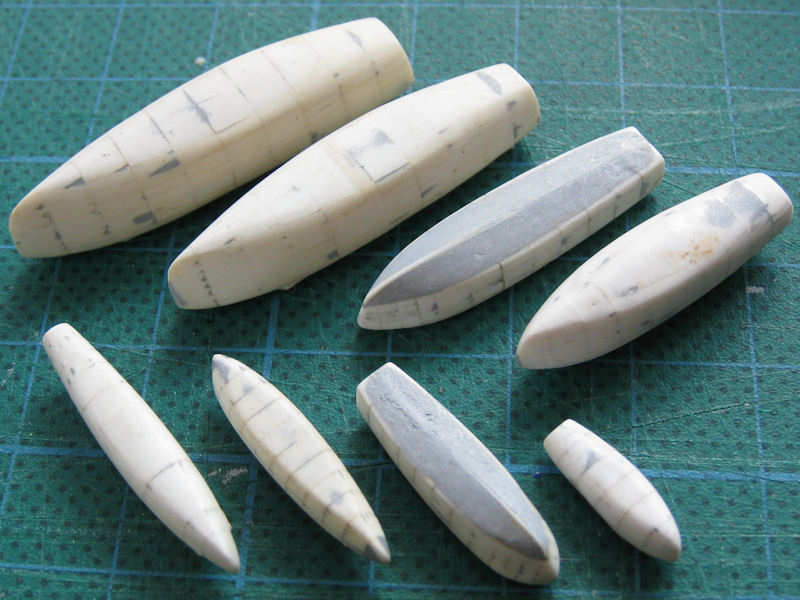
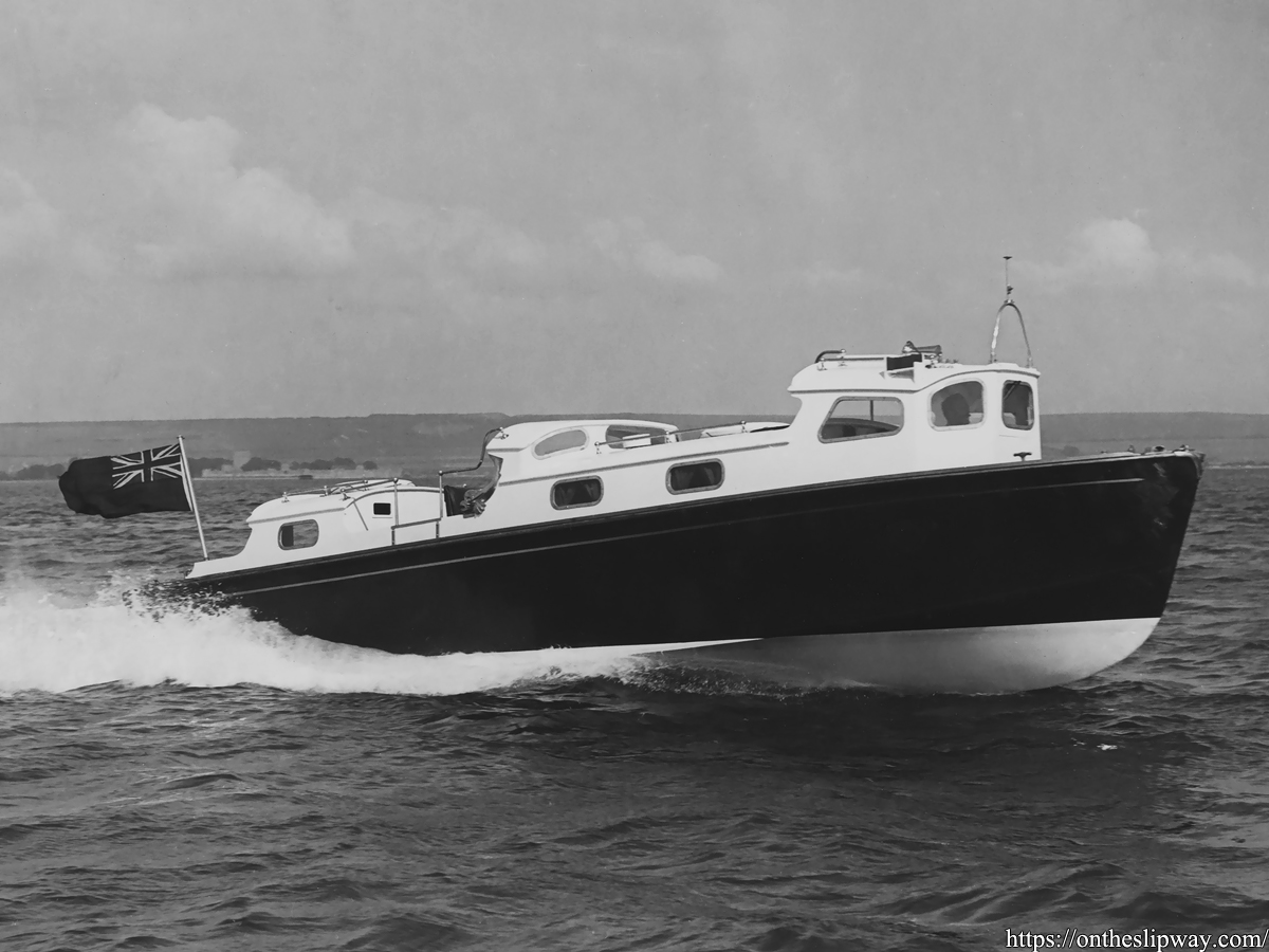
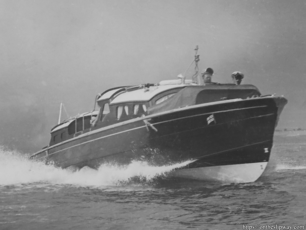
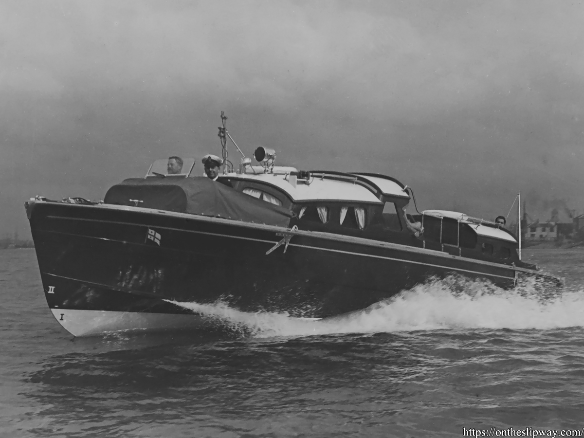
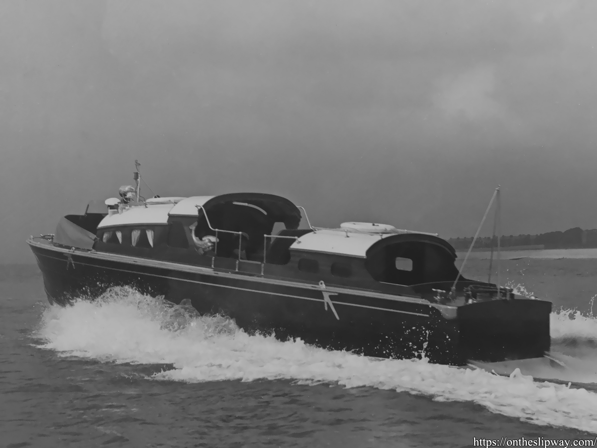
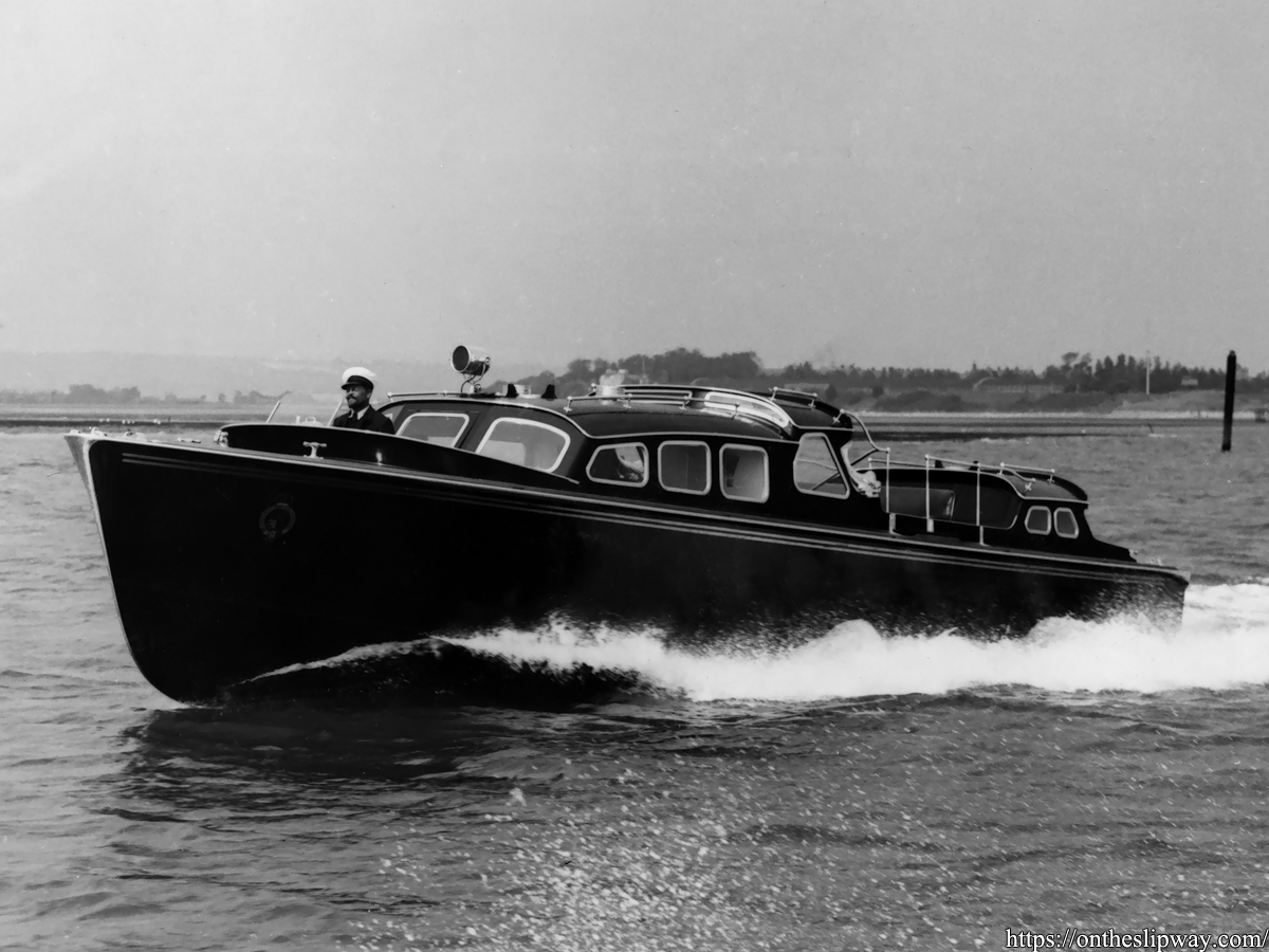
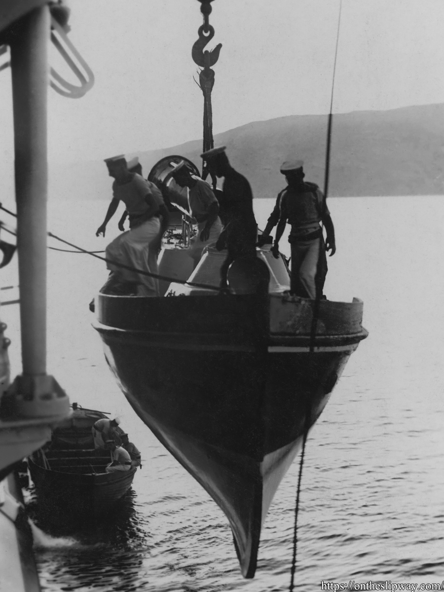
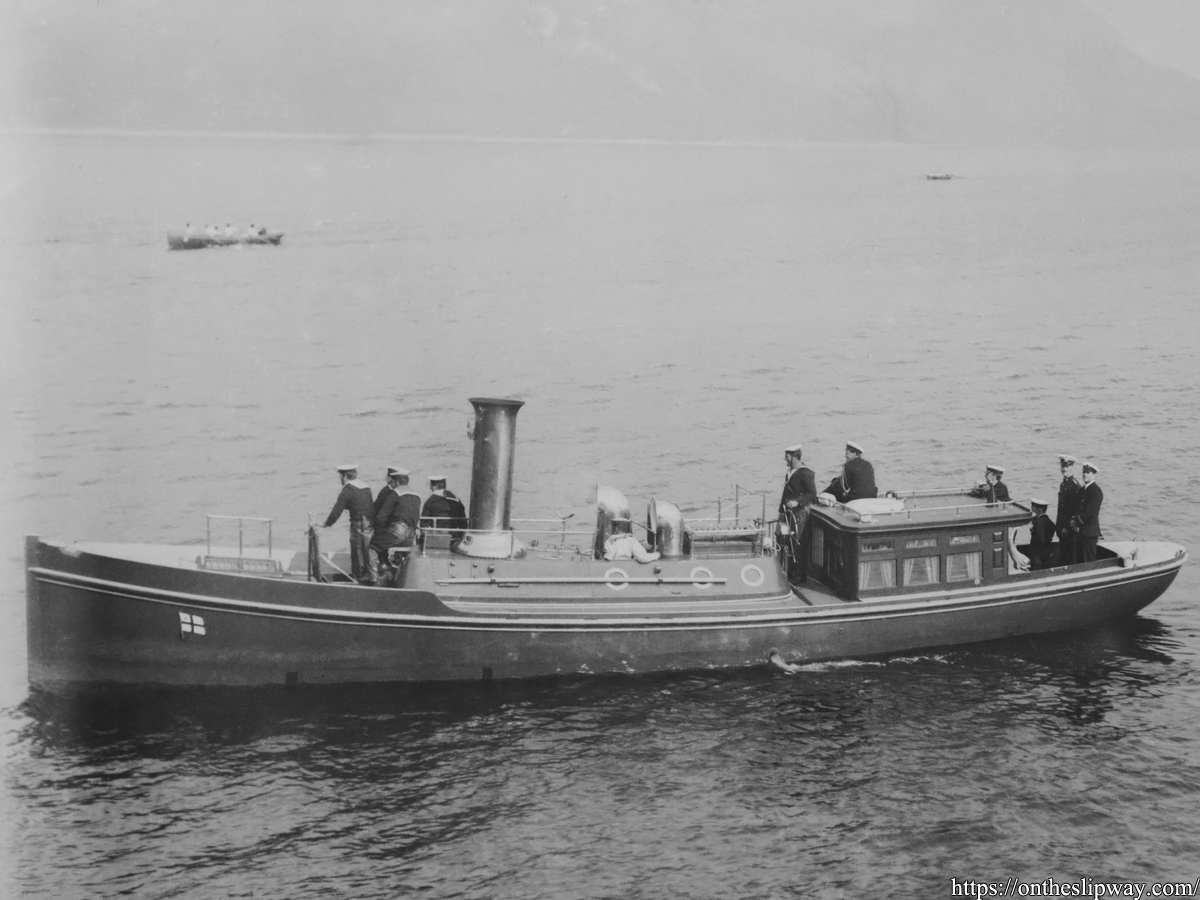
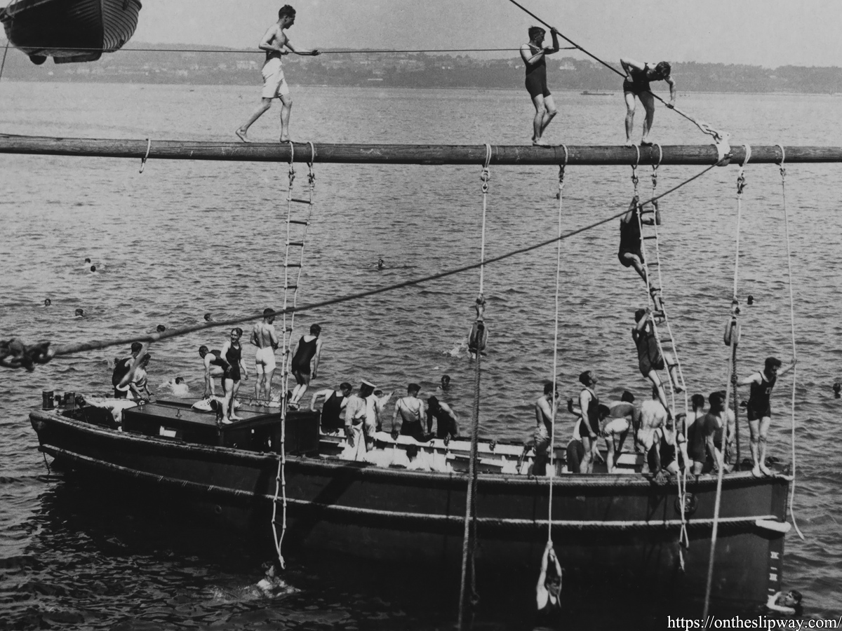
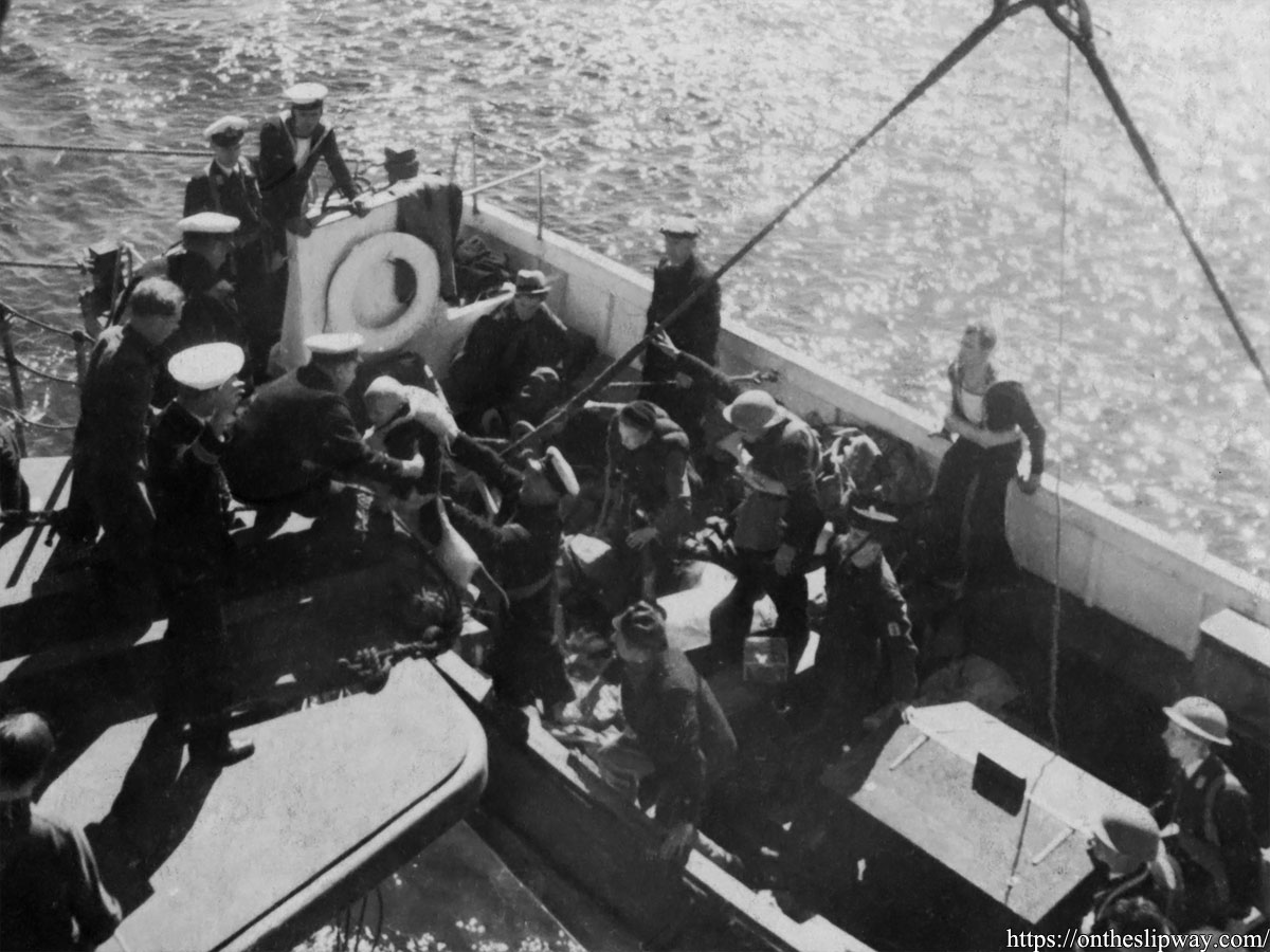
– Added 45ft Fast Motor Boats type III, 4 images


– Added 35 ft Vospers Admiral’s barge, one image

15/03/2025


– Added 3 images of the 35 ft Fast Motor Boat, Admiral’s barge version


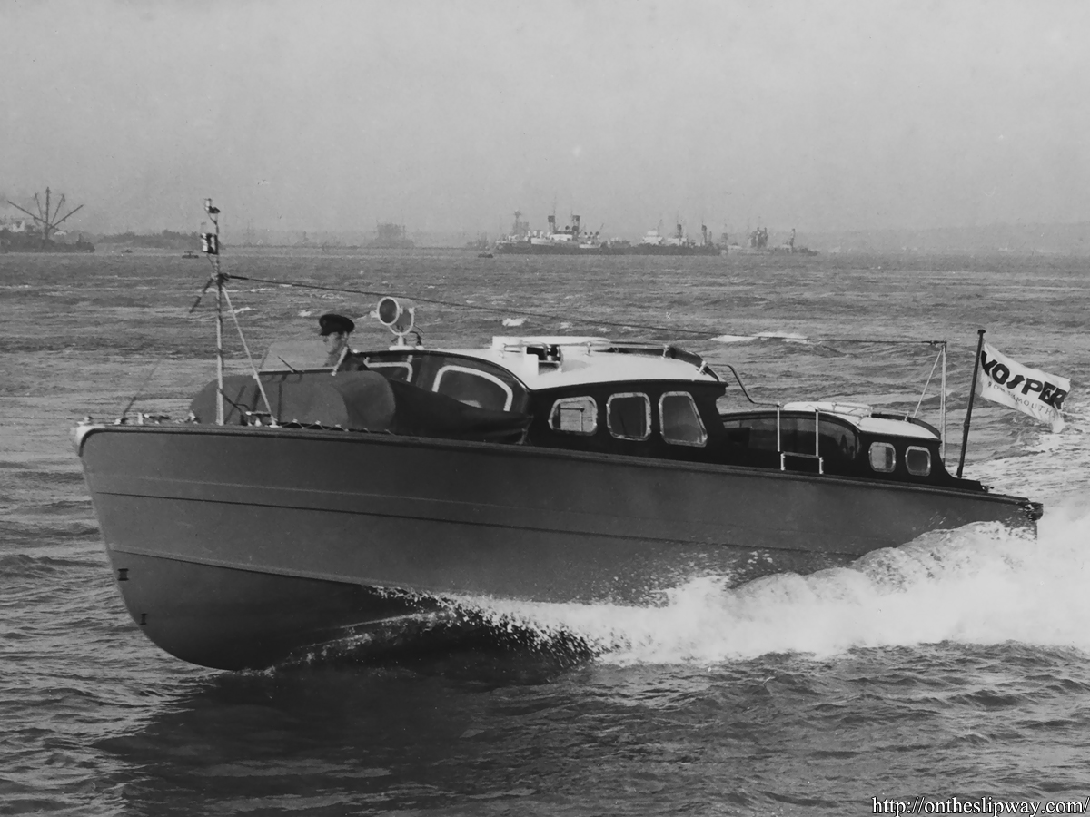
– Added 1 image of the 35 ft Fast Motor Boat, Vospers version

14/03/2025


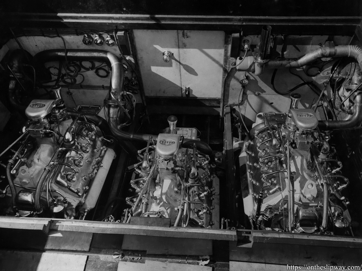
– Added 2 images of the 40 ft Royal Barge (trials, engine compartment)

09/03/2025


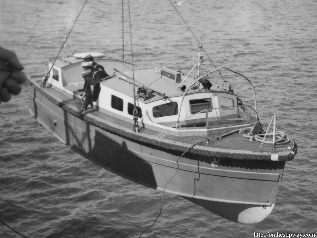
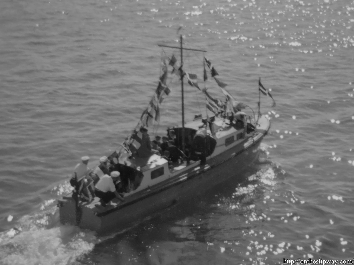
– Added 2 images of the 35 ft Fast Motor Boat, HMS Devonshire)


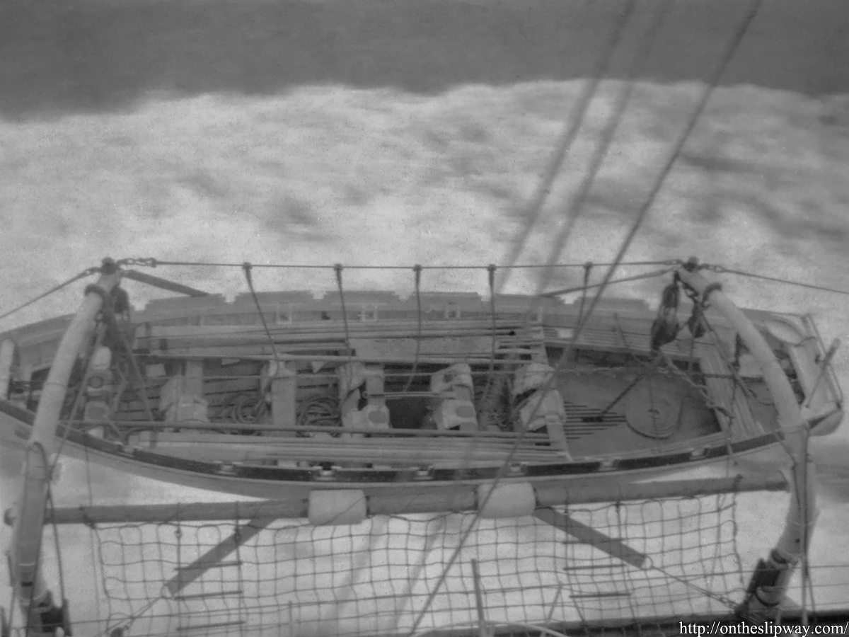
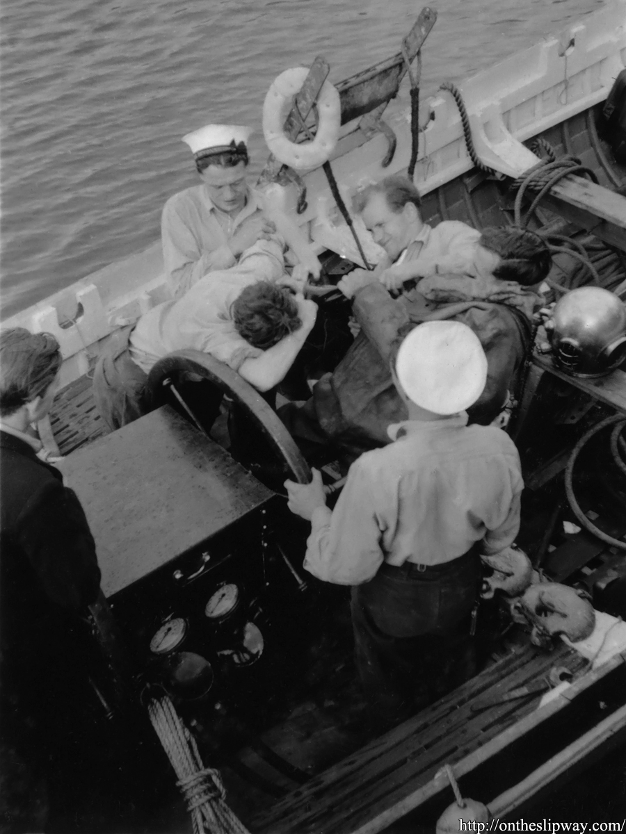
– Added 5 images of the 32 ft Cutter, HMS Devonshire)

13/09/24


– Added 2 images of the 50 ft steam pinnace (HMS Royal Sovereign)

– Added 1 image of the 45 ft admiral’s barge (HMS Warspite)

15/06/24

– Added 1 image of a 45 ft Motor Launch (standard type)

22/03/24

– Added 1 image of HMS Renown’s 45 ft Motor Launch (light type)

12/02/24
– Added 2 images of HMS Dorsetshire’s 35ft Motor Pinnace

07/10/23
– Added 1 image of HMS Prince of Wales’ 25ft FMB (presumably)

01/10/23
– Added two scans of drawings of the 32 ft cutter (from McDermaid & Manual of Seamanship)

21/09/23
– Added 1 image of the 40 ft Royal Barge (rear view, trials)

04/09/23
– Added list of yards to main boat page as a reminder; to be appended
– Added 1 image of the 32 ft cutter (HMS Hood)
– Added 1 image of the 50 ft steam pinnace (HMS Hood)

03/09/23
– Added Vospers advert to main boat page with ID’s insofar as I can determine
– Added placeholder for 20 ft Fast Tender
– Added 4images of the 32 ft cutter

11/08/23
– Added 1 IWM link(Q 18011) to balsa raft
– Added 1 IWM link (A 7776) 45 ft Motor Launch (light type)
– Added 32ft cutter plus link to Albatross pdf

08/08/23
– Added scan from Newton clinker/carvel/diagonal defs

05/07/23

– Added 1 IWM link (A1519) of HMS Revenge’s 45ft standard type launch

03/04/23
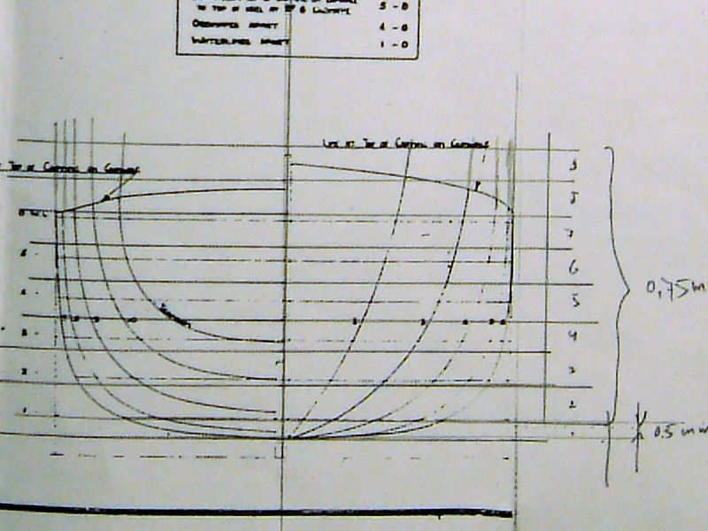
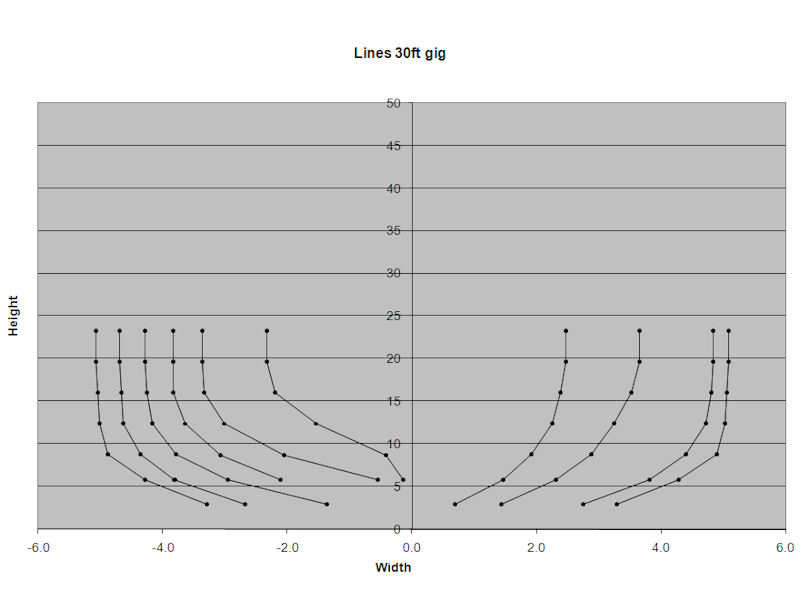
– Added 1 image of 30ft gig

19/02/23
– Added 40 ft Royal Barge, 2 scans, 1 IWM link

17/12/22
– split 45ft motor launch into standard and light type pages

11/11/22
– Added image of 27ft whaler in Gibraltar, 1938
– Added 30ft gig, added one image

06/11/22
– Added image of a 35 ft Fast Motor Boat Type I from HMS Southampton
– Added image of a 35 ft Fast Motor Boat Type II from HMS Superb
– Added image of two 45 ft Fast Motor Boats Type II aboard HMS Repulse.

08/06/22
– Added image of King George V and Admiral Jellicoe in a  50 ft Steam Picket.

01/06/22
– Added thee images of HMS Vanguard’s 45 ft Diesel Picket

08/03/22
– Added (same) overpriced image of HMS Ramillies’ on both 50ft Steam Picket and 45 ft Motor launch pages

07/03/22
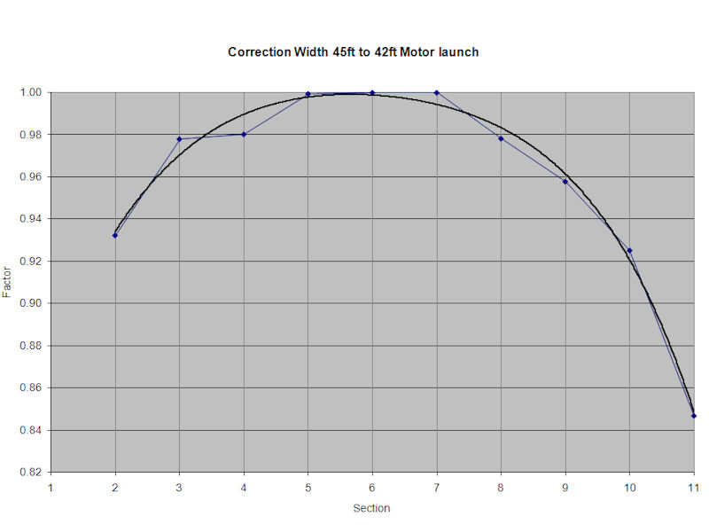
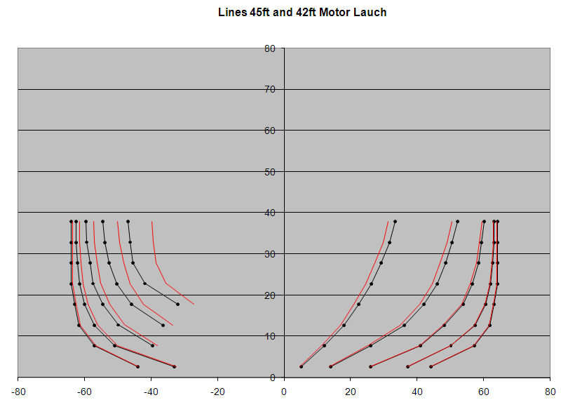
– 42 ft Motor Launch: blank page added. Adding comment to it and 45 ft regarding number of rubbers at the side (1 and 2 for the 42 and 456 ft respectively)

27/02/22
– 45ft Diesel Picket: adding ref. to history.naval.mil of Somerville’s barge (?)

30/11/21
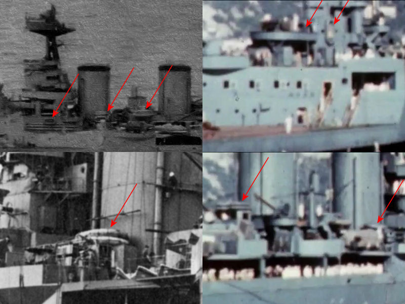
– Carley floats; 2 image added (Sheffield/Victorious)

26/10/21
– 35 ft Fast Motor Boat type 2, one image added

24/10/21
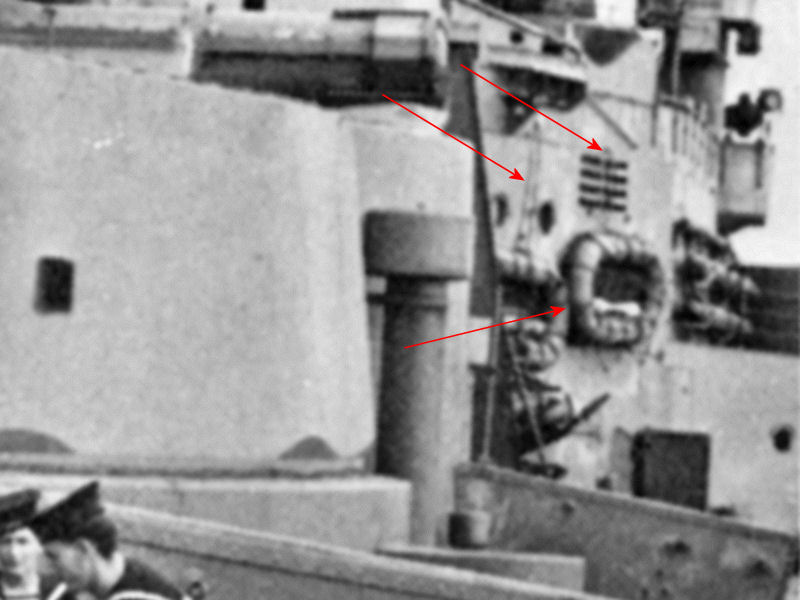
– Added Night Life Buoy, four images

22/10/21
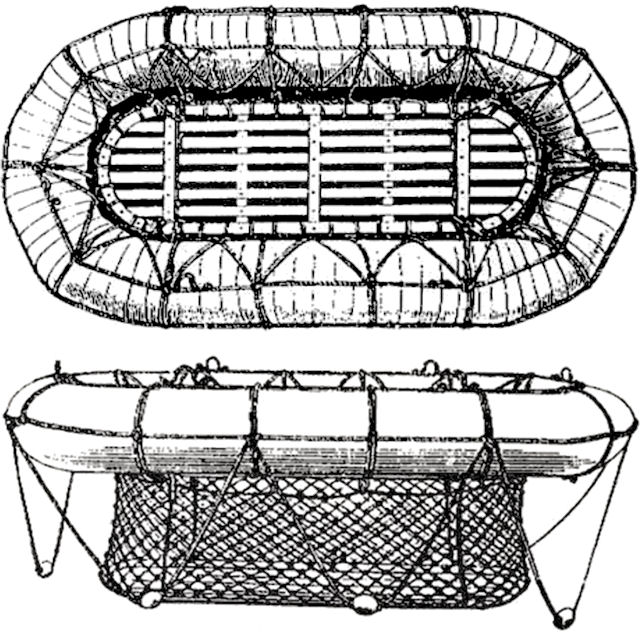
– Added Balsa raft, two images

03/07/21
– Added 37.5 ft RAF Seaplane Tender, one image
– Added 35 ft Fast Motor Boat type 2, one image

27/05/21-
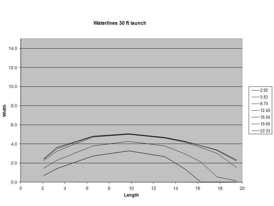
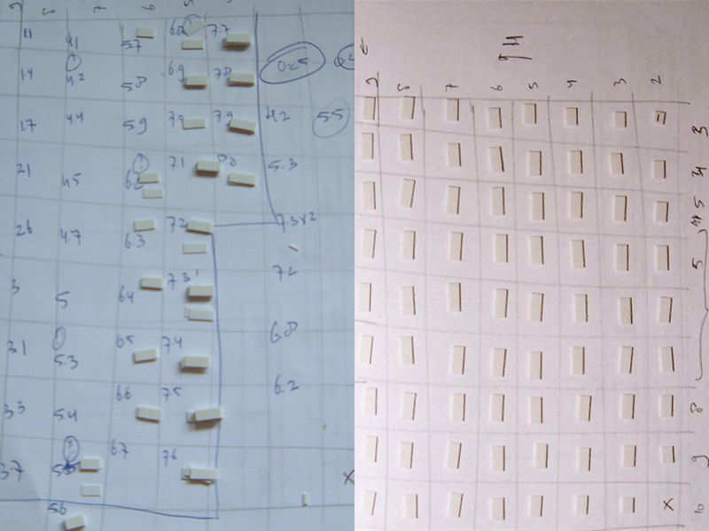
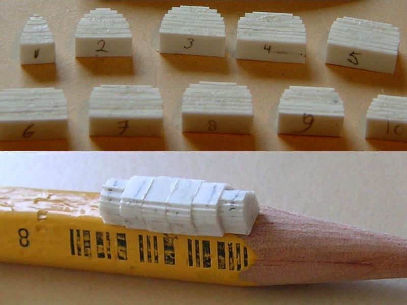
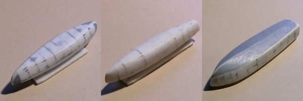
– Added 30 ft Fast Motor Boat, two images
15/05/21
– Added IWM A 8404 to 35 ft Fast Motor Boat type 1

18/01/21
– Added 45 ft Fast Motor Picket Boat (Thornycroft), GA from Lavery’s Churchill’s Navy.
– Added 45 ft Fast Motor Boat – Type II (British Power Boat). Moved images of wrongly ID’s images from 35 ft Fast Motor Boat Type I to this page.

14/01/21
– Added image of Rodney’s 27ft Whaler Picket
– Added images of Resolution’s & Nelson’s 50ft Steam Picket
– Added Rafts & Floats, Denton Raft & Carley Floats.

11/01/21
– Added remarks from info sheets to all posts
– Indicated drawing of the 45ft Motor Launch is of the light type only.

09/01/21
– Added 30 ft Motor Pinnace, GA, lines (no info sheet available)
– Added 32 ft Motor Cutter, GA
– Added 35 ft Fast Motor Boat type 2, GA, lines, info sheet
– Added 36 ft Harbour Launch, GA, info sheet

07/01/21
– Added 35 ft Motor Pinnace, GA, lines, info sheet
– Added 36 ft Motor & Pulling Pinnace, GA, lines, info sheet

06/01/21
– Added 14 ft Sailing Dinghy (placeholder)
– Added 30 ft Gig (placeholder)
– Added 50 ft Steam pinnace (placeholder)

05/01/21
– added 25 ft Fast Motor Boat
– added 35 ft Fast Motor Boat type 2 (placeholder)
– added 35 ft Fast Motor Boat type 3
– added 45 ft Motor Barge

04/01/21:
– Page initiated
– Added 16ft FMB: GA, lines, info sheet
– Added 25ft Motor Cutter: GA, lines, info sheet
– Added 35ft FMB Admiral’s Barge: Image, IWM links
– Added 35ft FMB – Seaplane tender: IWM links
– Added 45ft FMB & Barge: GA, lines
– Added 45ft Diesel Picket: IWM links

Carley Floats

I started these Carley floats about a year earlier while we were in the middle of rebuilding our house leaving little space for any modeling (the model was stored). The floats didn’t require the model to be at hand for fitting and I wanted to do something. So, some time for minor parts. Ahston et al. (1993) published a thorough investigation on the loss of the HMAS Sydney and a related Carley float; one float was apparently the only remnant for HMAS Sydney, a cruiser lost with all hands after a battle with the German auxiliary cruiser, HSK Kormoran, in November 1941. This report contains a bit of particularly useful information.

The Carley float is a simple combination of copper tubes with a cork, cotton, and canvas covering. A wooden grating that could be lowered in the water was fastened with rope where you could ‘stand’.  The even less fortunate were expected to cling on to the ropes around the float making  it not much more than a large life ring for groups. I can image you can only survive with such a float for a few days when the weather is favorable. Note the characteristic way in which the rope is wound around the tubing, showing rope going around the entire float and around the circular section, but also rope at an angle at the inside. I wanted to capture this specific detail. Before starting, I had to know which types of float were carried by HMS Hood as the exact dimensions of the floats weren’t written down anywhere I looked.  Ahston et al. give a table of the types of rafts available at the time:

No Size Tube Diameter
5 3ft 6in x 6 ft 12in
6 3ft 9in x 6ft 6in 13in
7 4ft x 7ft 14in
8 4ft 6in x 7ft 6in 14in
19 5ft x 8ft 14.5in
20 5ft x 10ft 15.5in
14 6ft x 10ft 16in
15 6ft6in x 10ft6in 17in
16 7ft x 12ft 18in
17 8ft x 12ft 19in
18 9ft x 14ft 20in

It is noted that each float was fitted with two paddles (four for No. 18), a boat hook and a painter (?); No 16 to 19 had two ladders. This is information as precise as one could wish.

This image shows two Carley floats hanging from a few ropes to the bridge bulkhead and, based on its relation with the bridge structure it’s suspended from,  I’m quite certain it has to be 5 feet wide based. Note that the ropes differ from the pattern usually observed: there should be some rope at the center of the float but it’s not. I haven’t seen a single image of a float with the pattern as seen here so I guess the crew repatterned the float? This detail was omitted from the raft models though.

I found out that the closest matches are Nos 19, 20, and 17. The Nos 19 are fitted against the bridge superstructure and on the disinfector house, No 20 is on the superstructure between the funnels and fitted to a side bulkhead of the aft searchlight platform and No 17 is mounted against the aft bulkhead of the searchlight platform. The position and number of floats aboard HMS Hood seems to differ greatly over the years, but I think this is fair assessment of what float goes where for April 1941. Note that the floats to the port side of the forward funnel appear to be lying on some structure. Instead of worrying about the type of Carley float, the real question is: what is this structure? More about this later below.

The model floats themselves were made from styrene rod. You first need to bend the rod into shape. I played with boiling them, putting the parts in the oven and I eventually used a cigarette lighter on rod curved around the end of a drill with the right diameter. You only need to heat the part for a fraction of a second or it will melt or start to burn. Each float consists of two halves that do not have a tendency to bend back. Next, I used the drill press to make a drilling jig. At left you can see the outlines with a few 0,3mm drills. I glued thick styrene strip against these drills, let it dry, put in the floats and drilled away. I used the cross table of the drill press for a reproducible pattern. The result is a series of drilled-in rings, here for the 5×10 models.

The rope pattern can be simulated with brass wire. Gluing small pieces along the raft gives a lot of glue spots and doesn’t really look very good. So,  thought it would be nice to sow the ropes with 0.1 mm brass wire. The real Carley floats aren’t very neat, so making this rope pattern by hand gives with the same variation. Here’s an example of the largest float so that you can actually see how these floats were rigged. I started with gluing the end of the wire to the inside to the float, out of sight and not clogging up one of the holes (1).  I then went around the float, zigzagging from point to point. The procedure is reversed and the cross pattern in the ropes appears (2). You constantly have to correct the wire with a pair of tweezers or push the wire through the hole with small drill to get the best result (3).  Simply pulling the wire taut every few runs doesn’t give a good result. Sometimes the wire breaks, but repairs are easy to do.

After the cross pattern was made I continued with the other ropes. I jumped from one hole to the next over the top surface of the float and put the wire through the hole (4). I went round the float once (5) and before pulling it taut,  I ran the wire back through the hole, ending where I started (6).  The wire around the float lies on top of the wires going from hole to hole, kept neatly in place.  In the end, a single wire produces the entire pattern and runs 4 times through each of the 0.3mm holes.  About 15cm/6in of brass wire is needed for the smallest float. Glue is added afterwards, at positions that are mostly out of sight. Even though this was fun to do, I wouldn’t recommend making all the floats by hand for a project where you need fifty floats. Next time I’ll cast a few for easy reproduction.

Now for that mystery block near the funnel. In the top left image you can see it hiding in plain sight and you really have to look closely or you won’t notice it is there at all. Top right shows the floats stacked on “it’. It appears to be fully closed. So, with no more to go on, what could it be? Other ships have similar blocks. For instance,  there are two of them on the boat deck on the King George V class battleships, shown bottom left (plus Carleys on top of it). Notice there’s a lot of planks and beams sticking out. Now, HMS Hood also carried a lot of planks and beams next to the funnels, deposited loosely and without any structure, so it might just be a neater and safer way for storage. On either side of the turrets of HMS Rodney (bottom right) you can find similar racks. These are shorted and appear to be oars storage racks? I cannot tell for sure for HMS Hood. I decided to add a randomly detailed rack to HMS Hood, based on the dimensions in the above images.

A second wire going around each float was added next. These wires are fixed with glue only and are not as ‘sturdy’ as the first wire. Some of the 5×8 and 5×10 floats were stacked. For the lower floats, on the wire you can see is actually added, not the complicated pattern.

The largest float is glued directly against the aft searchlight platform; there is some room between the etched grating and the outer ring so both are glued separately. One 5×10 float is also added, leaving just enough room for the door below it to open.

One other type of float is present aboard HMS Hood: a series of Denton Rafts. The top left image is of HMS Hood, showing the 16″ dinghy, two 5×10 Carley floats and a few Denton Rafts. The image right is the only other image I managed to find. The rafts were made from a simple piece of PE, glued to place usng a small template for easy centering. I have over 20 of these rafts to be added randomly on the structure between the funnels.

1) Ashton, J., Challenor, C., & Courtney, 1993, R.C.H., The scientific investigation of a Carley float at the Australian War Memorial, Technical Papers of the Australian War Memorial, No 1

How to make a miniature hull

Making a large full-hull model of a large model is one thing, making very small boats and launches is another and requires a different approach. You can hollow out small hulls or batter a sheet of metal against a plug, both with nice results. I chose to use vacuum forming, as it is repeatable and the hull is now from styrene which is easy to handle. My simple vacuum former was explained earlier here.

With a technique ready to be used for small hulls, the only thing left to build are the hulls themselves. After having spent some time tracking down the hull lines of all but two of HMS Hood’s boats and launches at the time of her sinking, I decided to make them all to scale with correct hull forms to match. Some of the pics I show you are already quite old and bad. At the time of this writing, most models are nearing a state of completion but are not quite ready yet.

This is a bad picture of the lines drawing of the 45ft motor launch. I’ve drawn a grid with plate thicknesses to scale, in this case 0.75mm and 0.50mm. When the lines are mostly vertical you can do with thicker strips. Near the bottom of the launch, the lines change quickly and thinner plates are required. These points were measured and put into a spreadsheet, for which I use Microsoft Excel.

Plotting the measurements is a quick way to see if there are any measurement errors. I plotted both the stations and the waterlines and both must look right. (click images to open if they look poor in the post). Once you have the measurements right, you can start cutting the ingredients for the hull.

There are two basic hull forms for HMS Hood; the soft and hard chine types. The soft type hull requires many strips of different length, while the hard chine hull has fewer unique components. The left part of the image shows a collection of strips required for building a small hard-chine hull, the right part of the image shows all the strips laid out for easy construction of a soft-chine hull. In order to cut these strips accurately to size, please see the chopper page in the tips section.

The tiny hull is now built up by stacking the styrene strips. I only glue two or three strips at a time, aligning them by eye and squeezing them a bit with the caliper. After all sections are glued and the glue has dried, the sections were sanded down a bit and glued to each other. The result is a very clunky hull that might look like it isn’t going to be anything. I completely covered the part with putty. When it has dried, just sand away until no putty can be seen. The small hull just barely contains the shape you want, so once the putty is gone you’re left with small hull. At the bow (and some sterns) you need to be careful not to sand away too much. Without too much trouble, you form the plastic blocks into a reasonably faired shaped.

My first attempt is seen at left, with the bow reconstructed using putty. This isn’t necessary and the center image shows a hull make from styrene only. As both sections on either side of the maximum thickness are the same section width, I used strip twice as wide. The hard-chine boats were finished with putty. Note that very little putty remains on the hulls. Note that vacuum forming will damage the moulds a bit, so making a resin copy might be a good idea.

scaling hull lines

I could not find lines drawings of the 42ft motorized barge and the 16ft fast motor boat (skimming dish). I used lines drawings of similar hulls as a basis, with the 45ft barge as an template. For this barge I do have the top view, so I measured the top outline of this barge and used the 45 ft barge as a base template and scaled it accordingly.

The above chart plots the normalized ratio of the beam of the 42ft barge to the 45ft barge (local beam divided by maximum beam). I then use a small averaging polynomial to obtain a smooth curve (e.g., a trend line in Excel). The height can be scaled linearly, by taking new thinner plates. This may require measuring all data again for the new plate thicknesses.

The results are compared and look fine.

After the hulls are complete and vacuum formed, the hulls need to be trimmed to size. For this, I use another cutting template. The height is taken from the side view of the hulls. Cutting it by hand doesn’t really work for me and when you need a few identical hulls, I really want something to look repeatable.

Here’s a pic I took today of a few of the cutting templates for the various hulls.

Another pic of all miniature hulls except the hard-chine 16ft fast motor boat which I apparently misplaced indefinitely. HMS Hood carried a 16ft dinghy and a 16t fast motor boat, for your information, and not two identical 16ft boats. The top row, from left to right, shows the 45ft motorized barge, the 42ft motorized barge, the 35ft fast motor boat, and the 32ft motor cutters. The lower row shows the 30ft sailing gig, the 27ft naval whaler, the 25ft fast motor boat, and the 16ft dinghy. Note how well the different lines of the various hulls have worked out. For making these small boats, it’s important that the outline at the deck is correct so that the cabins are not off scale. Note that he 45ft and 42ft models, based on the same parent hull form, look very similar.
I have an example spreadsheet right here to scale one set of data to the next. Here is the 25ft-fast-motor-boat sheet that adds the number of required strips. It also has a section where the sides of the hull are straight, so all values are interpolated linearly. This sheet also scales all measured values to the right model scale. None of the sheets take the thickness of the vacuum formed plastic into account, so perhaps you need to make everything a bit thinner if you really want to be properly scaled. For these hulls, I don’t think it’s really necessary.

Copyright © 2025 On The Slipway

Theme by Anders NorenUp ↑