HMS Hood was fitted with three HACS Mk III* directors (High-Angle Control System). These small high-angle/low-angle rangefinders were fitted around 1939, replacing one HACS Mk II on the (aft) searchlight platform. Information on this particular rangefinder was very hard to come by, as the Mk III* was only fitted to a few ships for a brief period of time. Most photographs show the round Mk IV-VIs, and the Mk IIs don’t really look like the Mk IIIs. To make matters worse, HMS Hood was not fitted with the Mk III, but the Mk III*, but I think the distinction is only that the Mk III has a 12-foot rangefinder and the Mk III* has a 15 foot rangefinder. The “Anatomy of the Ship: HMS Hood” by John Roberts shows a 3D view, most likely retraced from a picture but that’s about it. The good thing about scratch building is that everything takes so much time that you can sit around and wait for the information to sprout on the web. Strangely enough, this is exactly what happened, on the site of Godfrey Dykes. This site is colorful, to say the least, and may trigger epileptic fits, but I was ecstatic just finding the information.
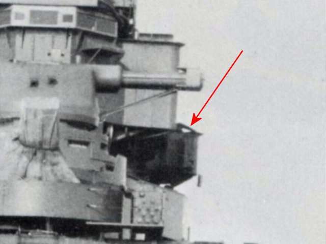
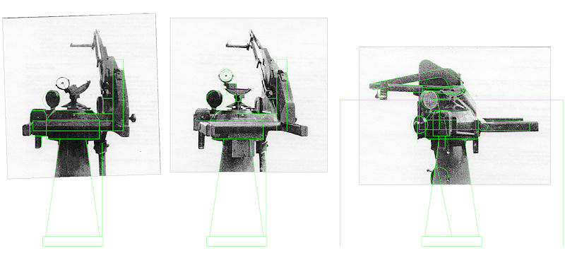
The pictures on that site are cut up into 6 strange sub drawings, not entirely along well-accepted lines for cropping images but seemingly random. Not really a problem for Paint-Shop Pro. I first knitted the images together, making sure all parts scaled equally well by the pixel. I then imported the drawing into AutoCAD and remodeled the rangefinder taking the distance of the 15 rangefinder to scale the drawing. This drawing formed the basis for my work plan. There is only one really good shot of the rangefinder taken from above (check your references, most books show this picture), a few of various pictures of the ship and one picture of the rangefinder from the wreck. The official HMS Hood site later added similar information to its site, plus a few documents I exchanged with them, more than trumping the information on the site by Dykes. However, by this time the model was already nearly complete and there was no conflicting information. How’s that for a change?
With this information I was able to not only make an accurate model of the rangefinder which is a first (well, to me it is, most kits have some HACS-resembling blob, showing that the rangefinder s largely undocumented. Perhaps there are many British modeling clubs that have more information.), but I could even build a little bit of the interior. Although most kits and drawings show the rangefinder with a canvas cover, that cover is rarely seen on the photographs! The openings in the rangefinder’s roof are often covered with canvas, but not with the large hood.

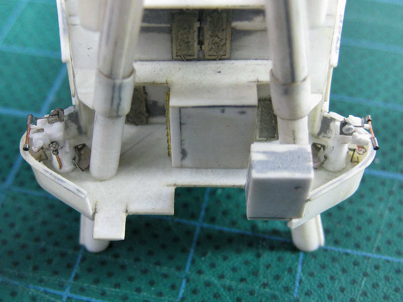
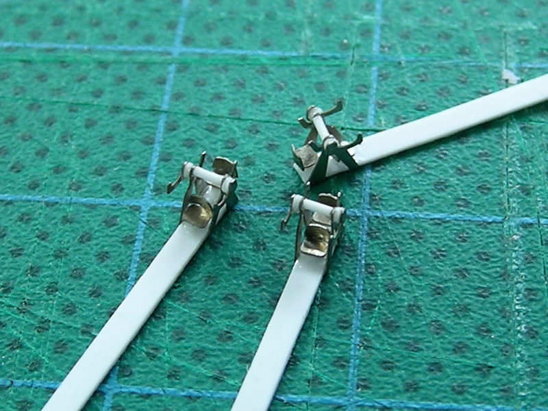
Well, wishing a rangefinder with an interior doesn’t make it so, and building it proved to be just as a challenge as building the secondary armament. The floor of the HACS is odd-angles only. This picture shows the base plate and the first walls. A bit of rod (and a spacer) will become the first part of the rangefinder arms. A small block is glued in the center as a support for the front plate.

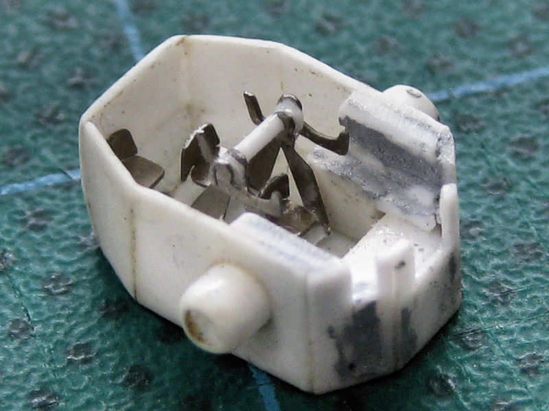
The frame of the HACS is nearly complete. The complex shape at the front is simulating using blocks and putty. Note that the rear panel is sloped at its lower end.

There is a smaller rangefinder with some optical equipment in the HACS. I etched the frame, but I made a series of errors. The top right pic shows I added a few disks, so that I could later cut the frame to pieces (lower left). I then added the frame to a strip, so that the base of the frame fits in the HACS. Note I use a very long strip, this makes handling the part a lot easier.
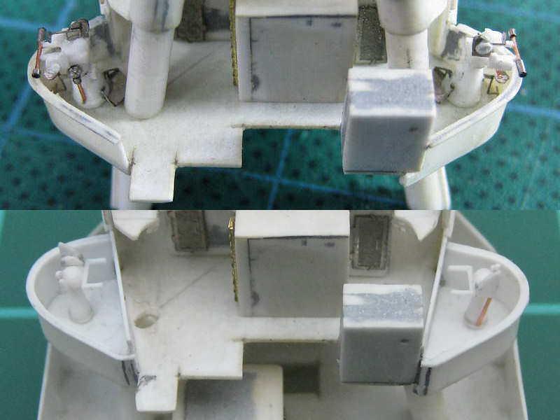
The rest of the etched part was added back to the frame and I even added a few chairs. How cute! At this point I wondered how much of the interior remains to be seen and whether I should stop here or whether I should continue adding more detail.
Fine, I added the commander’s chair at the back and I later added two chairs, one on either side of the center rangefinder. There is actually a sixth chair next to the commander’s chair but that one didn’t make it. Now the rangefinder fits within the body of the HACS. Note that I really needed to cut up the part, there isn’t much room.
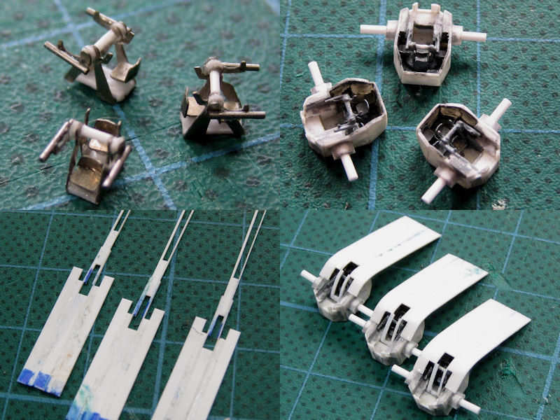
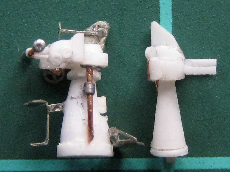
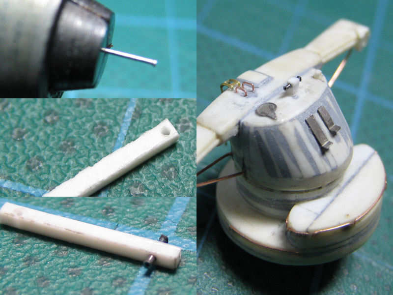
The top left image shows the rangefinder with some tubing added. I bought this tubing from Cammett Limited. This tubing by Scale Caliber has an inner diameter of 0.1 mm (0.039″) and an outer diameter of 0.3mm (0.118″). They have more, so I suggest hopping over to their site and order some. I cut the tubing to size using my drill, putting the knife to the tubing.
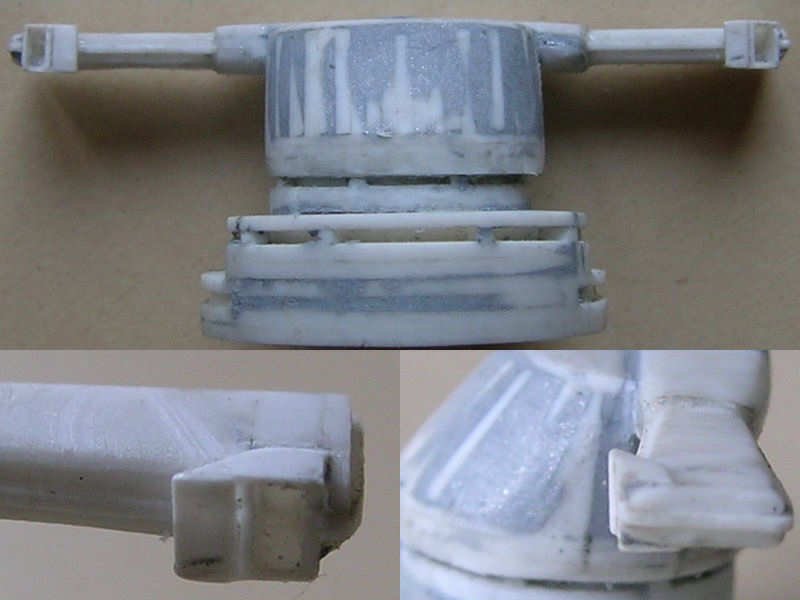
You can’t actually see that much of the interior. I gave it a quick coat of grey, as the inside will be hard to paint with the rooftop in place. The rooftop was made from a series of strips (bottom left). This part was cut to size (slightly) and glued into place. The lower-right image shows the roof in place. Actually, this is the second roof; the first attempt wasn’t very good.
Here you can see the HACS with its roof trimmed to size. Looks nice, don’t you think? Well, I don’t. Note that the roof of the aft rangefinder is not well-centered and required putty to get into shape and that the front of the roof curves rather badly at the inside of the HACS. I didn’t really keep track of the position of the roof relative to the rear wall, being rather occupied by getting it glued to the HACS in the first place, so that was also not very good.
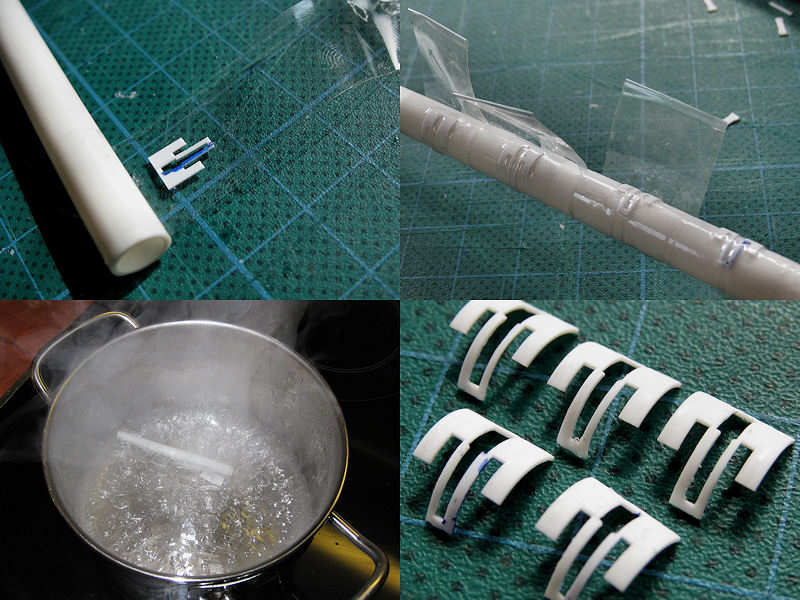
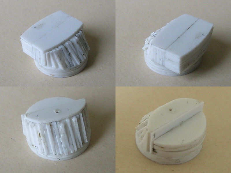
So, this is the roof Mk III (top left). I made six copies, so that I could keep the best three for the model. I taped five of them to a rod with sort-of the right diameter, having lost one already when sanding. The lower-left image shows the parts during boiling. This will soften the parts and they will keep their shapes when cooled down, so they do not have to be forced into a curve. It’s similar to the vacuum forming. The right pic shows the final result. The inner strips are so thin that bending them by force is exactly what made them look so poor with my previous attempt, so boiling them was a good idea.
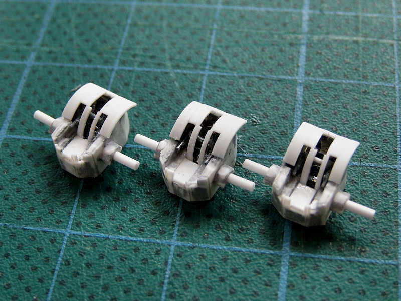
The HACS director models with the roofs in place. Much better! Without having to force them into shape, I could place them far more easily and I could pay more attention to the alignment with the rear wall. Even though the slits in the roof are thin, the suggestion of the interior looks very good! The connection of the roof with the HACS needs a little extra work though, plus that I broke off a part of the front of the center HACS model.
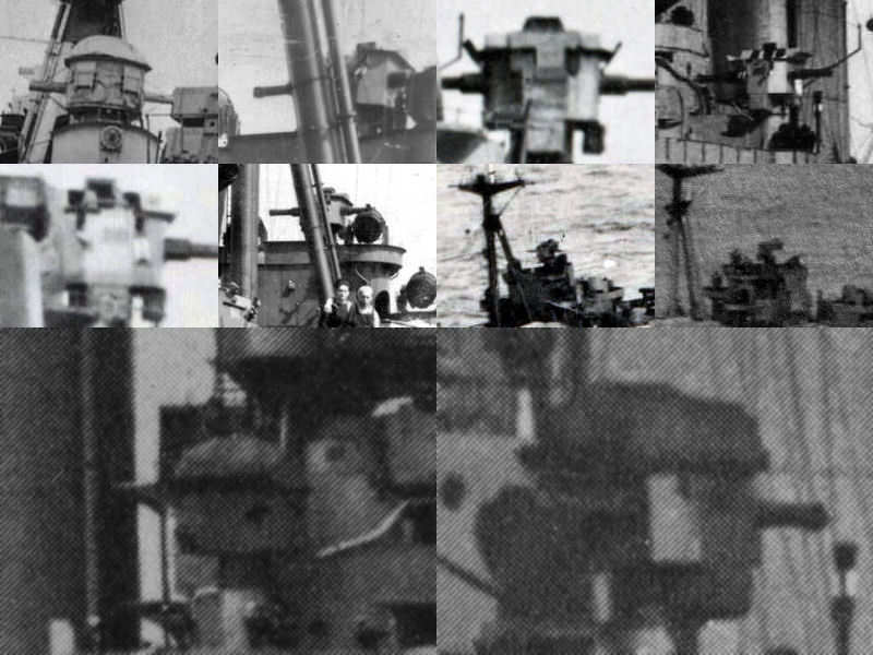
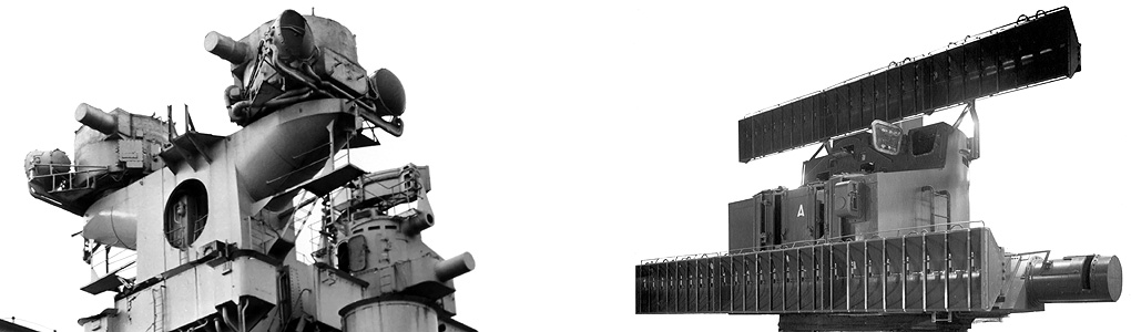
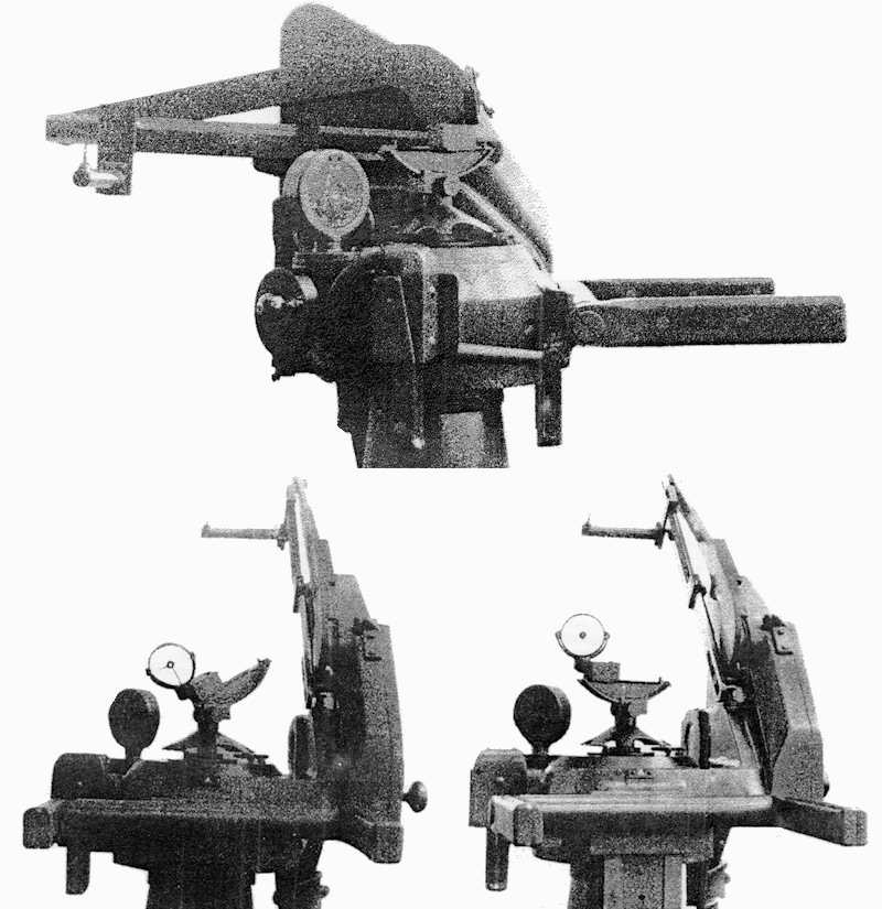
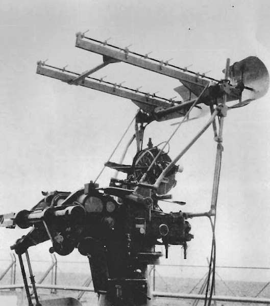
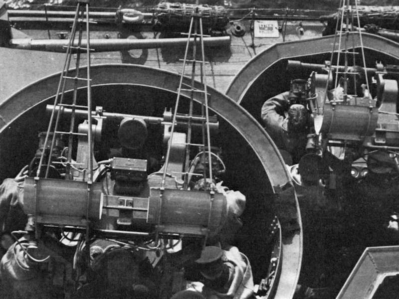
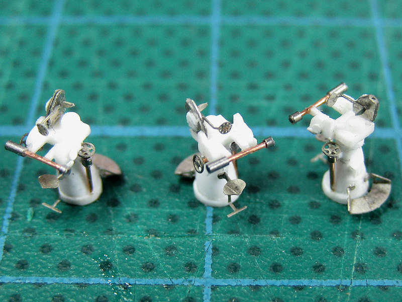
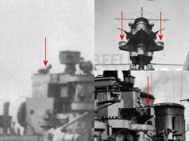
I received some comments that the interior is all nice and such, but invisible once the part is finished, as there is some large canvas cover on the rangefinder. This cover is present on most kits and drawings. If you look at the above picture, the top-left rangefinder indeed has this cover, but this is the HACS Mk II. The rest of the pictures show the Mk IIIs which nearly always are without the cover. The third pic from the left, top row, shows that the openings themselves were closed off with covers when not needed, but the larger cover is not used. The two right pictures on the lower row are taken from an aircraft with HMS Hood at sea. So, definitely no covers! This doesn’t mean that the rangefinders did not have them, because I did find two pictures with all the HACS MkIIIs with the top cover in place. So, to be fair, I posted these as well. Apparently, these covers were rarely used and keeping them down is the norm. From this little study is also visible that the rear rangefinder didn’t have these flanges that are clearly visible on the forward rangefinders. Also note that the aft rangefinder was always positioned facing forward.
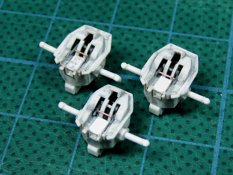
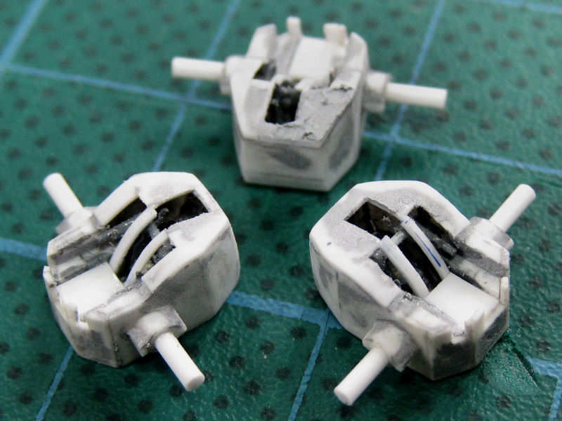
Here the units are complete with all detail except two covers on the front. The etched parts were etched at the wrong scale. The rangefinder to be placed aft (lowest here) doesn’t have the large flange. The interior remains well-visible.
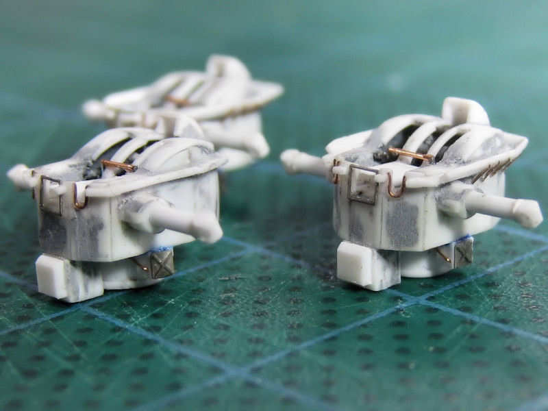
A side shot showing off some nice detail, such as the roll-engine compartment with a small etched detail part. The window frame on the front plate was also designed for the rangefinder.

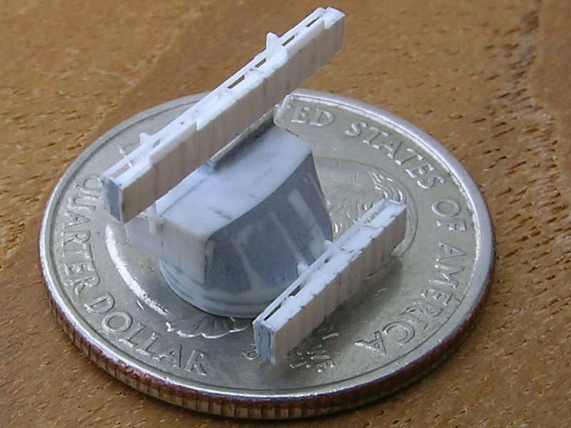
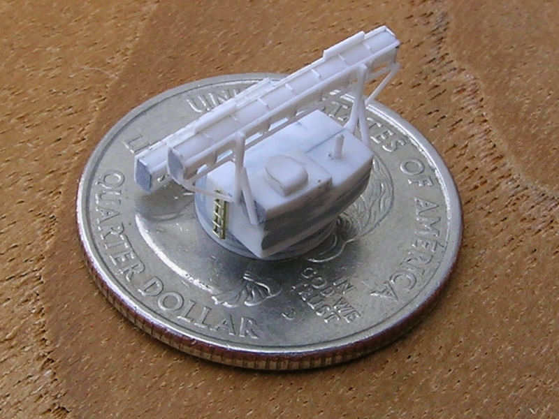
Just as a reminder that this is still a 1:350 model and that all pictures are taken at my camera’s macro setting. Ah, done!