
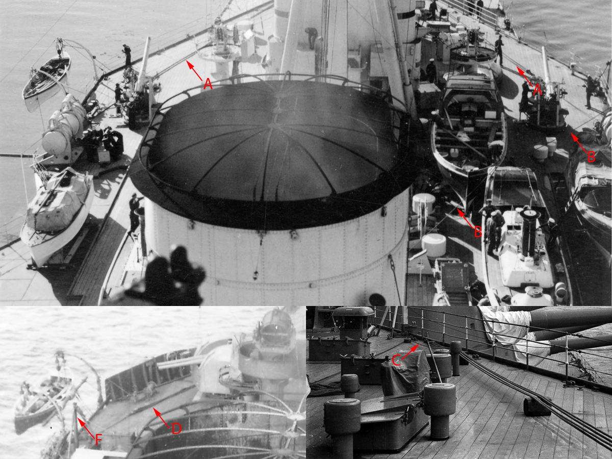
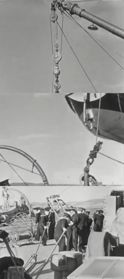
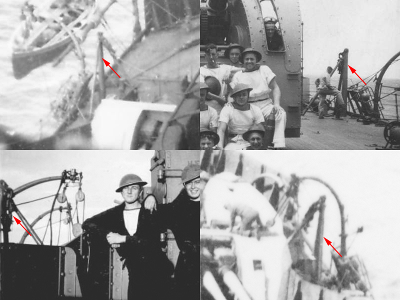
In Hood’s 1939 refit two 27ft whaler positions were added to the aft of the boat deck, replacing the cutters. I noticed there are a few ropes running from the end of the boat deck towards the davits (A); these ropes remained visible until the end of Hood’s career (D) when a small stump mast appeared as well (F). Looking closely at images of the boat deck I also found that a rope was running from the whaler position back to the derrick of the main mast (B); I could not find a good picture showing if it was the same rope as at (A). A system of two blocks was placed on the aft of the boat deck and the system was tied up somewhere out of sight between the skylights (C).
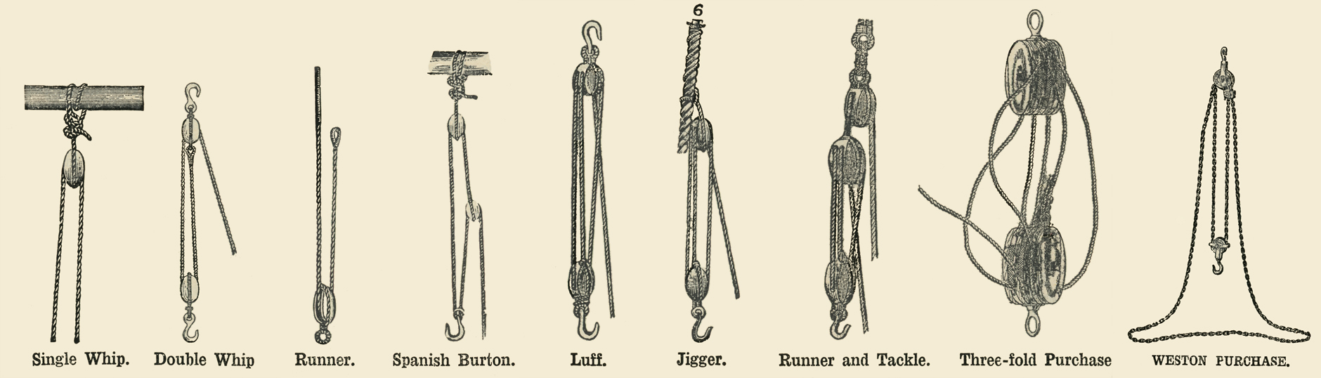
While scanning my trusty McDermaid & Manual of Seamanship I found the above images in the latter with a few examples of block variations (there are others, see https://www.hnsa.org/manuals-documents/age-of-sail/textbook-of-seamanship/tackles/). It appears when a rope goes back and forth between two blocks it’s called a purchase when that number is even and a luff when that number is odd. So that would mean in the image above our mystery cable is a luff plus a separate block running the rope towards the skylights (I wonder how long it will take a modeller of a man-o-war to master instantly naming a hoisting system correctly).
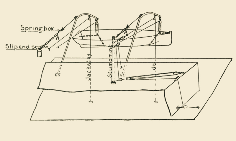
Stump masts, ropes, blocks and pulleys are not uncommon near davits as this sketch shows, throwing me further off track of the purpose of the boat deck luff. But, if you want to lower a boat then one might think that the block should be much farther away from the davits or you don’t have enough rope left; the luff aboard HMS Hood is meant to hoist something in.
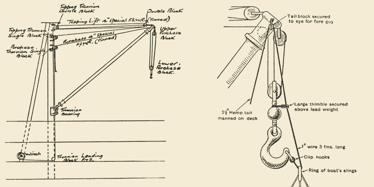
The drawings of the main mast do not show any other lines other than the lift & purchase lines plus a thrice line—an additional line when hoisting a boat in that is used to pull the ring of the boat’s sling over the hook—- but that is not a line that would require a system of blocks. Note that the cabling layout for the hook is called a (single?) purchase and not a(n inverted) double whip.
I later found the rope in action in this clip where the crew is lowering a boat; this rope is not meant to do any hoisting itself and appears to be merely a side guy to control the lateral movement of the main derrick. I’m now fairly certain that in the top images ropes A and B are the same.
That leaves the stump mast; I think it was added to clear the 4″ turret when working the derrick and is not related to the davits at all. I estimated its height at 8 feet based on railing height and a side view showing the top of the mast.
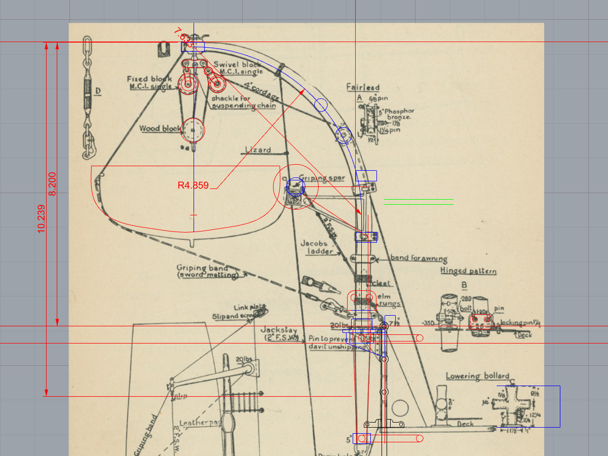
This is a small image from McDermaid showing the davits for a cutter; it has a staghorn bollard including measurements for scale. This drawing does not match the dimensions of the davits aboard HMS Hood but with a few pics I made an estimate.
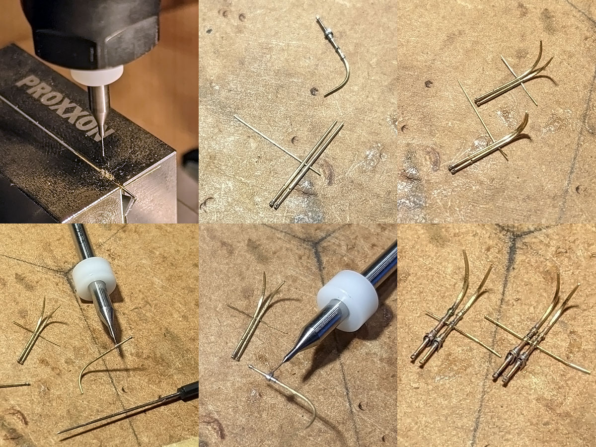
The davits were made from 0.5mm brass rod with both ends tapered to 0.3mm. The pairs of holes were drilled in as explained in this post. Two davits were pairwise bent into the right position and then angled inward by about 12 degrees. Small 0.3mm rings from a 0.7mm tube with 0.2mm holes were soldered to the davits (bottom left); next two small etched parts and the rest of the tubes were added. After a few hours the davits were complete.
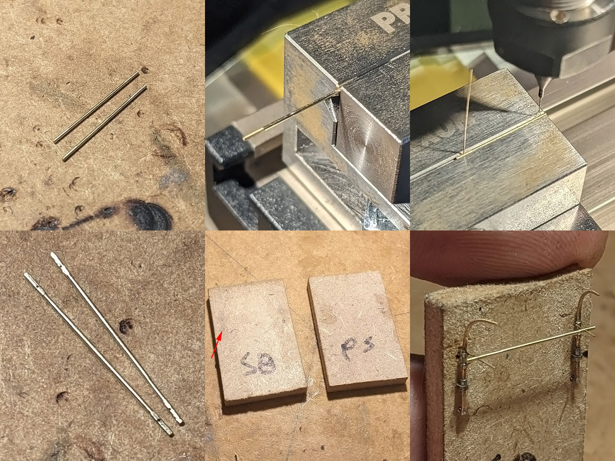
The griping spar was next; I didn’t file the ends square but flattened them in the vice. Two small 0.2mm holes were drilled in where the spar will be supported. I also made two “construction sites” from MDF with four small 0.4mm tubes that were added to the model as well. The davits and spars fit really well on this temporary position. The spar isn’t soldered into place yet, two cushions need to be added that I’ll make from magic sculpt pressed gently into a whaler model for a good fit, but these small models needed to be made first.
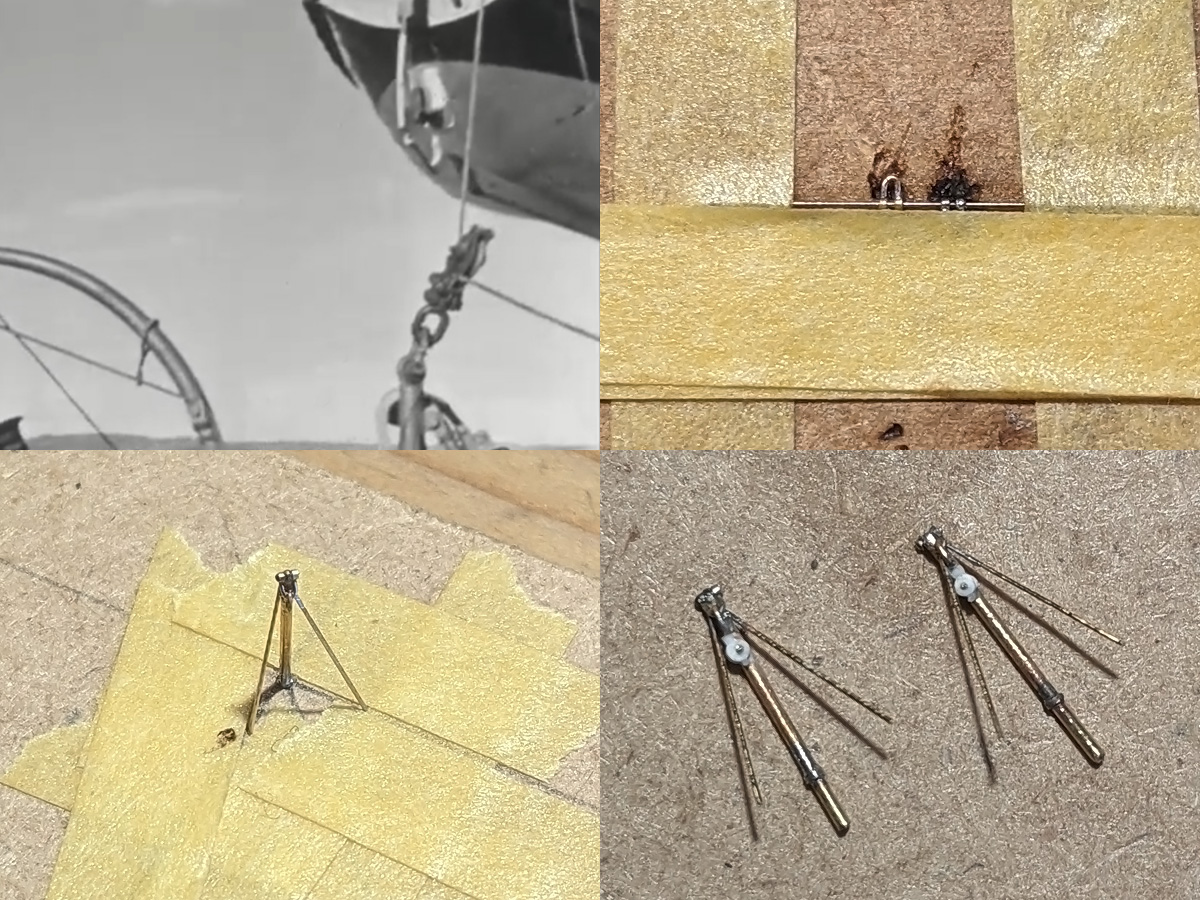
The stump mast image top left shows a single lug, a studless shackle and a pulley. The lugs % shackles were made using the same methods as detailed in the post /Ground Tackle part I, top-right showing two small lugs and four rings held in position using take and a 0.2mm drill (on which the solder doesn’t hold which is very convenient). The small tripod was soldered into place using a small jig made from MDF and tape. A tiny bit of reheating was enough to fix the small angled supports with a tiny bit of CA to prevent the lug and the shackle falling to pieces. The pulley was made from 0.5 and 0.7mm discs punched from 0.13mm styrene.
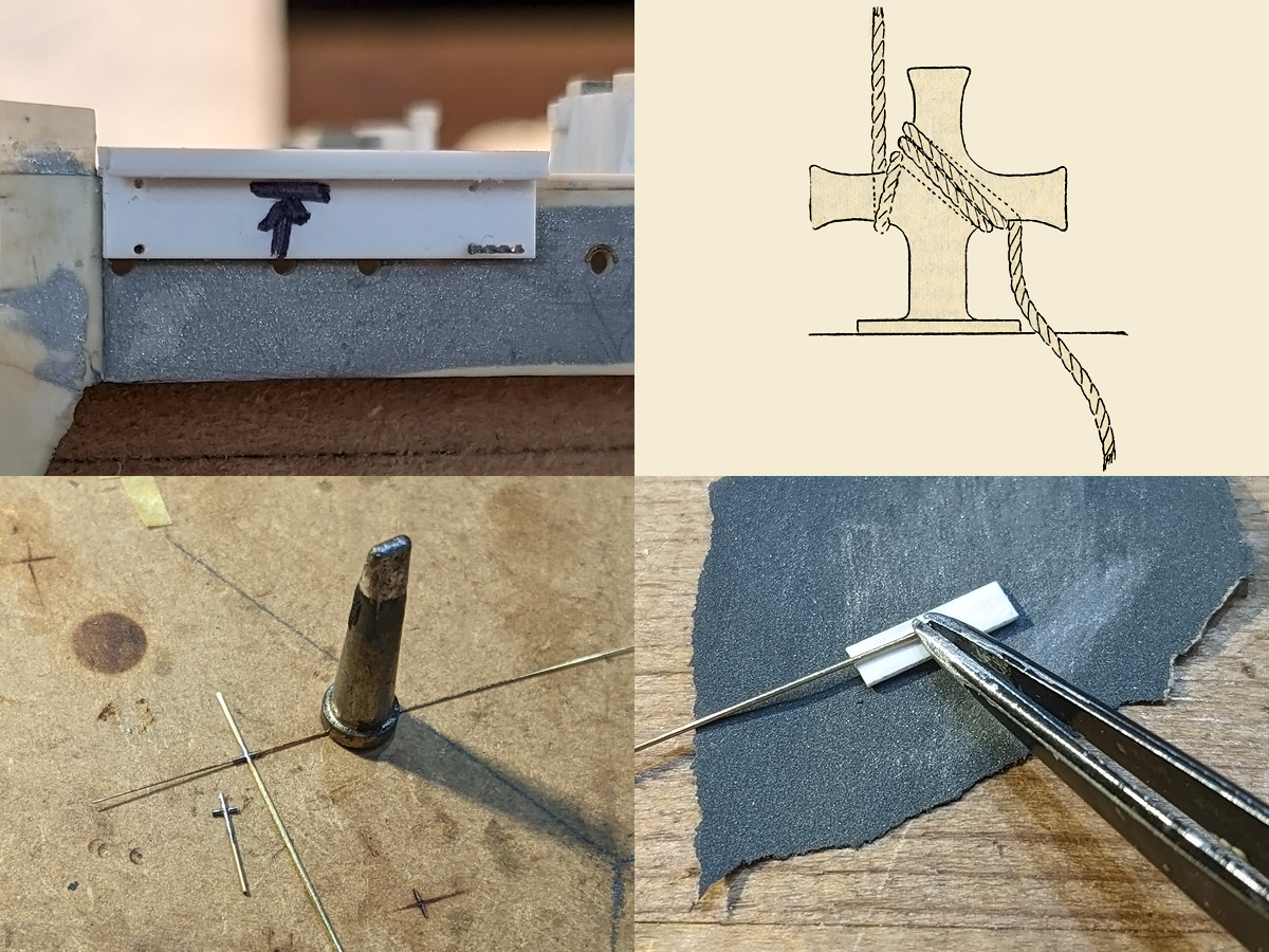
The small milling machine was used to make a jig to transfer the location of the mounting pins to the side, showing the jig pinned in place by a drill after the first hole. A few more tubes were added to the deck to receive the stump mast and four staghorn bollards. I tried making these bollards by simply soldering three rods together and then sanding them to size, but this proved to be very hard at first. Pinning down the arms with tape doesn’t work as the flux prevents the tape from sticking; using the hold & fold solves the pinning problem but that device acts as a heat sink preventing the solder from flowing (even with the largest soldering tip and at maximum burn). Drilling in the 0.4mm vertical rods and then adding a few 0.4mm tubes over a 0.2mm wire was—counter-intuitively—very easy and fast to do. These were sanded to size by sticking each end in a styrene strip of the right thickness and were then added to the boat deck model.