Page 12 of 27

Funnels, Part II

Continuing from part I

With the soldering going so well I decided to solder on a bit more and had some parts redesigned and etched.

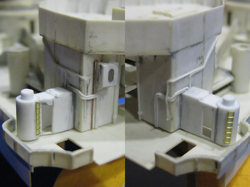
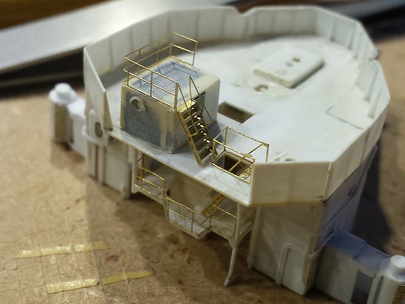
Some minor detail was added first. The two ladders on the inside of the funnel are placed with a jig so that the gantry will link up to it nicely. The ladder is by Aber, one of the few commercial products I have used (I’ll probably use my own ladders in the future). The steam pipes cluttered around the funnel are made from rod; drilled in, chopped up to give it that knuckle on the end, and fixed with brass wire. That is, I didn’t glue the pipes to the wire yet to avoid handling damage in that area.

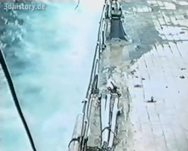
Note that there is a bit of damage on the aft funnel that was later patched up; a nice piece of detail to add. The top left image also shows the typical Royal Navy approach to painting the ship; they do not use the foot rails found on axis battleships with a series of pulleys and planks to stand on. It doesn’t seem very safe but it does save you building an awful lot of these foot rails. The pulleys are etched parts, folded once.

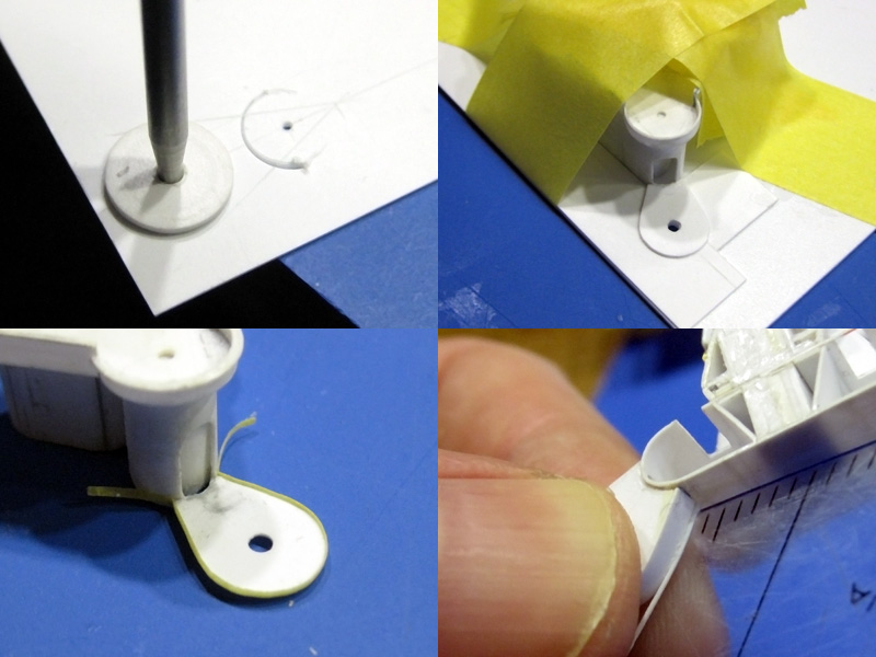
Here’s a sketch of the funnel cage.  The crew could access the funnel from below, climb to the top and fix an awning to the cage (but usually did so only when the boilers were out). I made this small drawing in Autocad of the funnel cage with a series of 0.2mm holes for the supports of the cage and for a few pins to hold the cage in place. A ring goes around the funnel cap supporting a series of arches. One large grande arche is on the ship center line. I decided to make a drilling template for the supports and support pins.

The inside of the funnel isn’t as perfect as I’d hoped and deformed a bit with all these layers of plastic going around it. Perhaps all these brass wires in the inside are a bit too taut. I already botched up fitting several well-executed gantries so I came up with a disposable fitting template to check the goodness of fit; should have come up with that earlier!

The soldering of the gantry itself was slightly tricky and I had to tape the parts down at every step. I added the solder like I’d normally add CA; a few spots to fix the part, with a line of solder when it’s more or less in place.

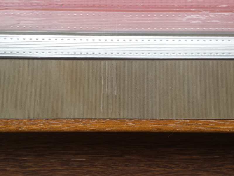
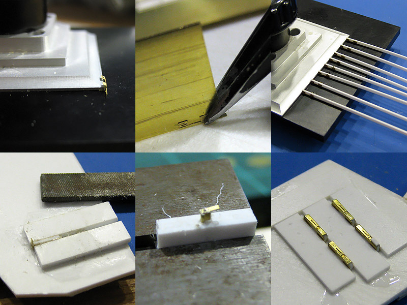
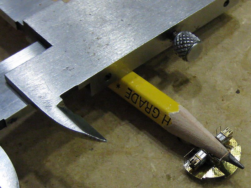
Now the template for the cage. I bought a pin chuck to hold the 0.2mm drills. When I put the pin chuck in the Proxxon chuck (Röhm actually) and dutifully fixed the chuck with the key at all three positions as my tool shop ordered me to do, the pin chuck was not centered correctly; I really had to try, try and try again until it was finally worked. I even bought a new chuck so that I now have a nicely centered chuck/pin chuck combination never to be separated. I made a picture of the spinning drill as proof it finally worked. I started with the drill protruding only a few mms from the chuck but the drill will usually walk away slightly—drilling off center—and the drill will break when the chuck is near the work piece; I lost three drills before I figured this out. So, I finally had the drill sticking about 1 cm or so from the chuck so that it could flex. The result is shown at right after drilling and with the positioning pins. The tubes at the center are supports for the arcs of the cage, made from aluminum so that the brass wire won’t be soldered to them.

I had some room to spare on my last etch so I added a folding template for the ring of the cage; the brass was far too stiff to use this template but it did work to check the shape. I started by rolling the handle of my X-acto knife over a 0.2mm brass wire until the diameter was correct. With some pressure from a pair of pliers I added the parallel center until the shape was more or less right. The wire was transferred to the jig, held in place by tape and the supports were added one by one. I started opposite where the ends of the ring meet and cut the ring to size only when nearly all supports were in place. The positioning pins could then be removed.

The arcs were bent into shape and checked against a high-tech drawing. The grande arche was added first, followed by the other arches. Note that the ends of each arc have a 90-degree bend; this allowed me to temporarily tape the arc to the jig and keep the direction of the arc upwards; otherwise it will just fall over all the time. I fixed the end of a single arch to the grande arch, fix the arch to the ring, and reapply to both ends in succession. By doing this, there is no stress in the solder and when I apply heat to the center they do not change position (much).

Afterwards three etched parts were added on top of the intersections of all the arcs. The difficulty was not so much avoiding the desoldering of all arcs but aligning the etchings themselves. The cage could then be lifted from the jig. One cage was damaged beyond repair at this phase. One cage took between five and six hours to make; this time was mainly spent looking through the Optivisor and handling the parts with tweezers and the soldering iron until the alignment was to my satisfaction (which is never, naturally).

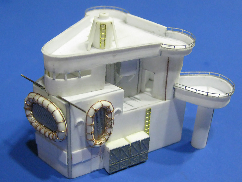
These funnels took more than a fair amount of planning and experimentation but now have a level of detail that I would not have thought possible a few years ago (cage and gantry are not fixed yet in this picture). The soldering allows for much better and clearer work than using super glue and it is much easier to correct.

Cordage and Hawser reels, Part II

Continuing from part I

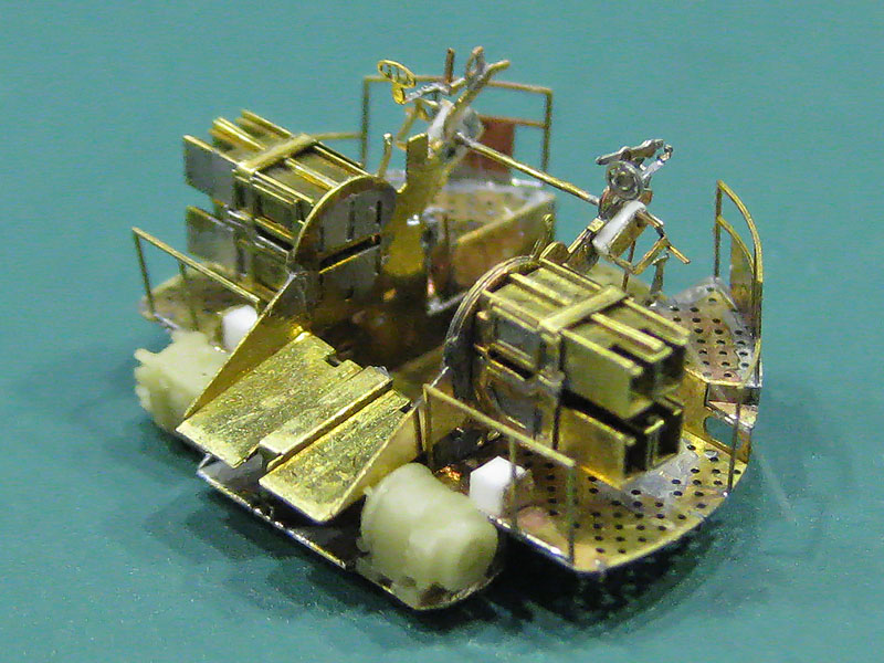
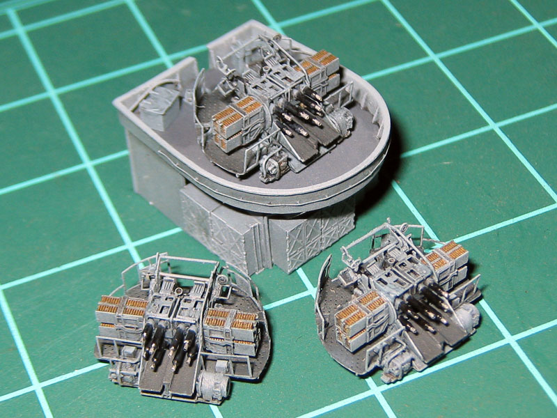
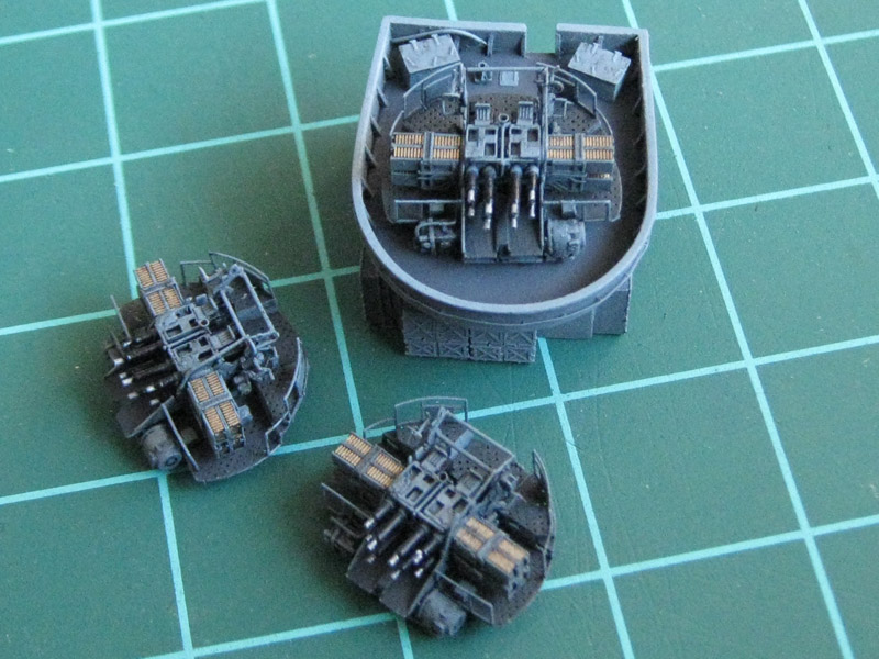
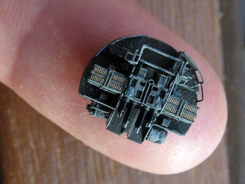
I’ve been exercising with soldering lately. I thought things were going wonderfully at first and I made a few fully soldered pompoms. Unfortunately, after a week they started to corrode and after a month parts started falling off. Repairs didn’t work and even superglue did no longer adhere to the metal at all (this never happened before!). I used the corrosion-free Tix flux that may have been the problem, either as I didn’t clean the parts properly afterwards or it simply isn’t corrosion free as some modelers on railroading forums claim? I don’t know really, but after a period of mourning for my pompoms I gathered my strength and I replaced all my soldering equipment and consumables. I finally found a nice Australian web shop called DCC Concepts with a nice how-to on soldering and their own range of solders and fluxes. They claim to have a no-clean non-toxic flux that I wanted to try and this solder/flux from DCC works really well. In the beginning I had some trouble as it didn’t run as smoothly as the Aber/Tix combination; however, that combination ran so well it ended up in a very very thin layer and a poor bond. I just have to be a bit more careful in the amount of solder I add for each joint.

I practiced on a new batch of cordage and hawser reels before trying the far more complicated pompom. I already made a batch but I had so much trouble gluing these parts together. If some part broke off during the final stages of construction, I really couldn’t repair it and had to start over. Understandably, the failure rate was very high.

1. Piece of MDF used as a disposable workbench.
2. Bottle of flux secured in a hole drilled in the MDF. It does really help avoid knocking the bottle, which I did when working with the Tix flux earlier (Staining the modelling table). The first day I constantly found myself wanted to shift the position of the bottle but now I’m used to it not being able to move.
3. An old brush for applying the flux.
4. A bag of parts to be soldered.
5. The DCC Saphire solder.
6. Stock rod, tube, and wire. This brass from Scientific Wire can actually be soldered, in contrast to winding wire I bought that has a coating.
7. A drill to open freshly cut tubing.
8. A toe-nail clipper for cutting (thin) rod and wire.
9. Calliper.
10. Assortment of files, knifes and tweezers.
11. Part storage area outline.
12. Soldering station by Weller with a variable iron temperature.
13. Soldering iron with the finest tip in the Weller assortment of fine tips.
14. Alcohol for pre/post soldering cleaning.
15. Bowl with alcohol to finished parts.
16. Maximum magnification Optivisor to check the bonds and quality of filing and such.
17. Tramin 2011 Pinot Grigio from the Alto Adige. Hensel 2011 Grauer Burgunder will also work. Soothes the nerves before soldering, dampens disappointment when parts spontaneously disintegrate, raises spirits when things finally go according to plan.

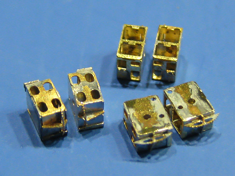
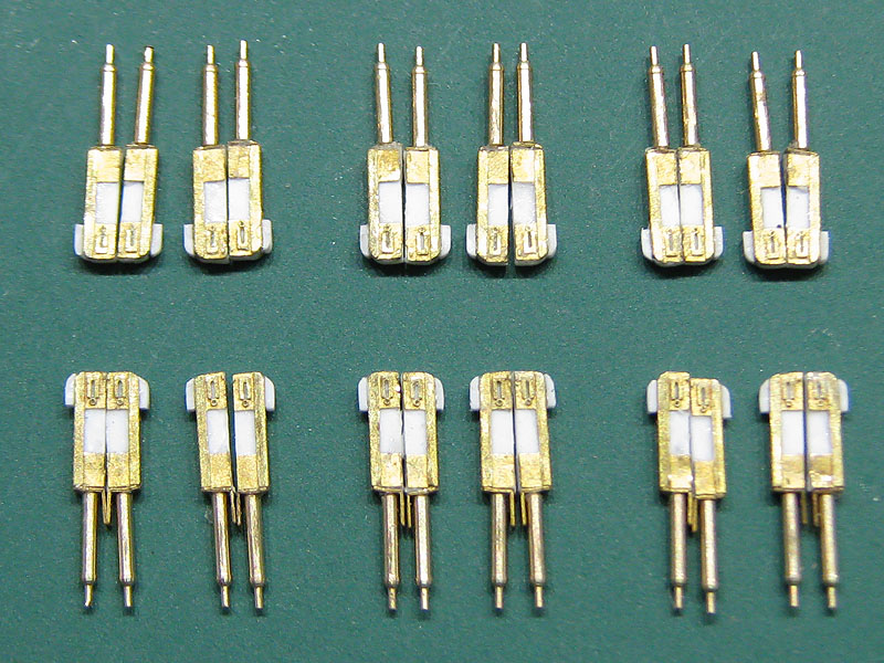
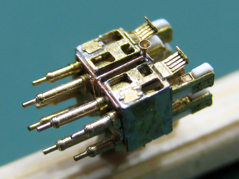
Now, I am not going to follow all the advice normally given for soldering work. For instance, I do not have an abrasive pen to clean the parts as the parts are much too small; holding them without damage is enough of a challenge already. Pre-tinning a part is often risky as you can clog delicate parts but sometimes works. You also can’t really pre-tin the soldering tip because the amount of solder you need is so small. Top-left shows a tiny chafing chipped from the solder. Now, slice is halved, and if necessary cut it two again. You can pick up the solder with the tip of the iron; you can see a tiny bead (top right. note that this is the smallest soldering iron tip that Weller sells with a 0.4mm tip). This works very well for applying a minute amount of solder that is sometimes already a bit too much. The bottom images show a tiny 0.5mm tube soldered to a 0.3mm wire; the wire centers the etched parts and the tube acts a spacer. I add flux to the wire, pre-tin the wire (no harm here), slide over the tube and add heat.

The two etched parts are cut from the fret, sanded and put in the “storage area outline”; they are so small and difficult to find that putting them on the same spot actually helps. Now, I drilled in a small 0.3mm hole on the base plate so that I can plug the 0.3 wire through the etched part (top center), add some flux and then heat while gently pushing the tube down with fine-tipped tweezers. The part is both held in place and aligned at the same time. It can help to use to Optivisor to see if the solder is really flowing; if the connection is bad the part will probably fall off anyway. The long end of the wire is clipped and the other etched part is added. This is more difficult as they need to be aligned with respect to each other and there is some risk of the first part getting loose, so some trial and error is required.
My cheap model pliers weren’t any good for clipping wire (most modeling tools aren’t) but my beautiful Zwilling toenail clippers were just perfect for the job. Afterwards the excess wire (nearly nothing) was filed off; this is a tricky part as it’s very easy to catapult the part if you’re not careful (need better tweezers). Afterwards the etched parts were folded. Here the optivisor came in really handy, showing me if I held the tweezers properly over the fold line. The image bottom left shows a poor example, risking folding over a hole present in the part. Bottom right shows a finished cordage reel; 2.5mm wide.
The hawser reels presented a much greater challenge; I needed to make drums with a 0.3mm hole for the center wire to align all parts. However, I haven’t been successful drilling in these small holes in brass. I started with a center drill of 0.5mm, giving only a gently tap to the end of the rod, but the small drill often wandered anyway. Even when the hole was centered perfectly the drill breaks, even when I drill very carefully using cutting oil and cleaning the drill every few tenths of a millimeter. Anyway, I gave up and ordered some stock tubing from Albion Alloys with a 0.3/0.5 inner/outer diameter. Drilling in a 0.5mm hole is very much easier and the tubes are very easy to cut to length

Making small brass tubes is now fairly easy for me. Setting the late at its highest rpm (only 3,000) I start with cutting the end of the stock brass (1) and cutting the rod to the correct diameter in very small steps (2). I bought some stock rod from Albion at the right diameter but I lost it… Next I position the 0.5mm hole with the center drill but I do not drill the hole yet (3). I change the cutting tool for the parting tool (the quick change tool holder is the best upgrade for the lathe). I position the parting tool, release the rod,push the rod back with the parting tool and fix the rod again in the chuck. This is my primitive way to reposition the parting tool at zero (4) and make a small groove with the parting tool (5). Then I apply the square flat file; I put the lathe in reverse so that  the file isn’t catapulted into my eye when I accidentally hit the chuck with the end. I think this is much safer (6). I continue slowly with the parting tool (7) and capture the small tube on the end of the drill (or center drill). I usually make a batch of them before reinserting them in the chuck (9), apply some cutting oil and drill them through.
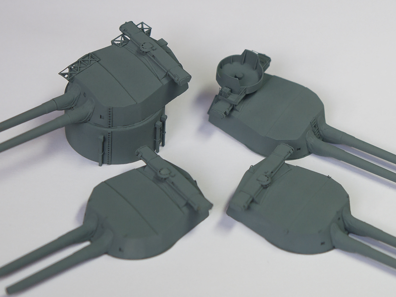
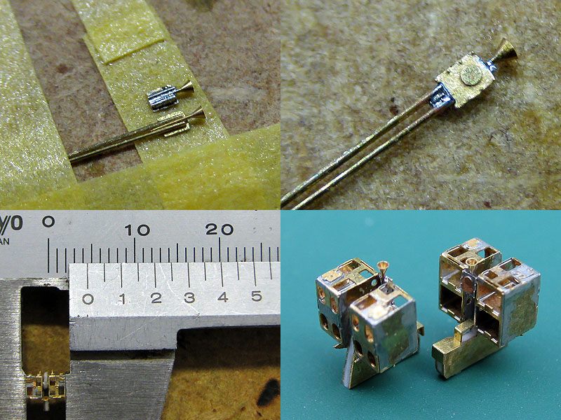
I took a few images of the largest hawser reel, consisting of 2 tubes and 7 etched parts.

The top four images show the small drums added to the 0.5mm tube. The tube is much to long but when the to tubes are soldered to each, I insert the part in my hand-held drill and cut the tube by hand. A small 0.3mm wire is then put through the tube. The etched parts at the side are actually three parts, so that I could capture a bit more detail. The first parts fit into each other and need to aligning, but the last part is held in placed by an old broken-off 0.3mm drill.

Like the cordage reel,. the hawsers are fixed to the bade plate and the parts are all soldered into place. This is a tricky part because all the parts get desoldered; I apply pressure with fine-tipped tweezers while the solder solidifies. The part is checked to see if everything still aligns nicely and of all the feel touch the deck properly; if not, the part is heated and realigned. The 0.3mm is then trimmed and filed smooth.
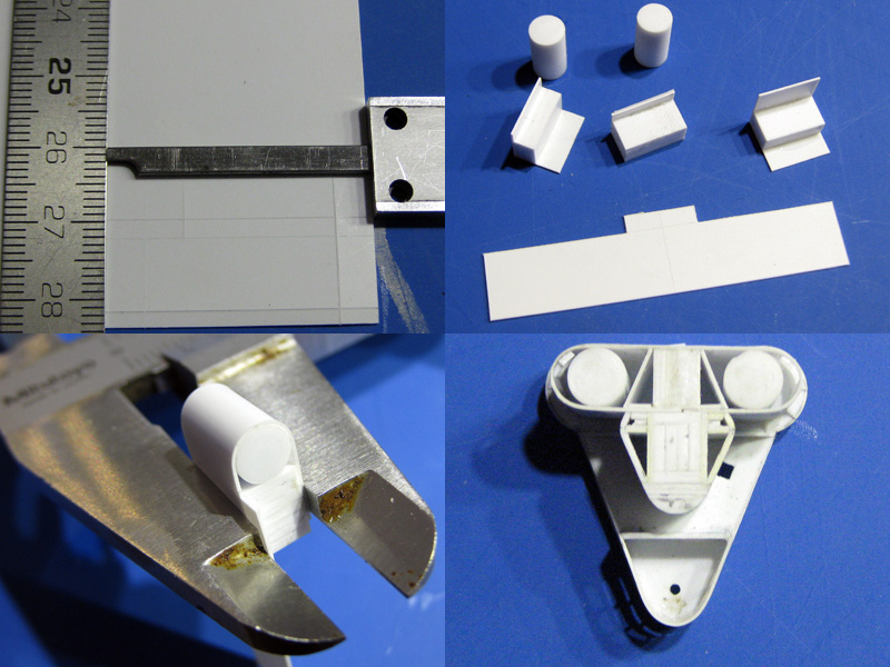
The small model is clamped into the caliper and a 0.15mm brass wire is soldered into place, cut to size and filed. If the rod breaks off during filing, then the bond wasn’t any good. Although the flux is sold as no-clean flux, I threw the parts int he ultrasonic cleaner anyway. This cleaned up the parts and improved the bond between the final two parts superglued to base of the small models.
Not the best picture, bit it givens a nice impression of the range of reels to be fitted to the model. Why doesn’t the reel at the center doesn’t have those two wires? Must be a failure I didn’t throw out.

Below decks

Not that many photographs are available of the weather deck amidships. This area was briefly out to the open but quickly covered by the shelter deck. Still, most drawings and the Anatomy of the Ship volume shows the location of vents and details to add.

It’s just a minor issue, but note that the bulwark was changed when the boat deck was extended. The position of the accommodation ladder was moved aft when the pompom were placed in the 1929-1931 refit. Note that the ladder is stored on deck in the upper image.  The fairlead apparently also switched position. Naturally, this means that the bollards placed on the deck were moved as well.  If you go to the Willis collection of the website of the HMS Hood association you’ll notice the bollards just aft of the first of the three 5.5″ guns and the fairlead itself. This change is missed by all drawings so the exact position was estimated to be between the first and second 5.5″ gun.

This image shows a few nice details. A 5.5″ ammo dredger hoist is seen at (A). All the 5.5″ ammo hoists weee removed by 1940, however, the 4″ ammo hoists on the shelter deck are all located exactly at the same location but one deck higher. As know the forward and after 5.5″ ammo magazines and shell rooms were converted to 4″ ammo magazines, I’m confident sure new ammo hoists were fitted even though these are not mentioned. At (B) a support stanchion is seen (with a white band) that are clearly indicated on the drawings. A ladder to the shelter deck is indicated at (C). There’s something at (D), but I haven’t been able to identify it. I’m not sure it was still present on HMS Hood in 1941 and decided not to add it.

On this nice side view of HMS Hood two large deck vents are seen at (A) and (B). Note that the vent at (B) is seen to face aft at  (C, from Warship Pictorial #20). A 5.5″ammo dredger hoist is visible at (D). Note that the cradles (E)  for the boats and launches are exactly above the support stanchions.

Pictures after HMS Hood’s various refits below decks are rare. Upon comparing pictures of HMS Hood from 1934 and 1939, it appears that support columns are placed below the 4″ guns at (A). The aft one is particularly vague. The R-class battleships do not have these columns below their 4″ gun mounts so perhaps I’m over-analyzing. Note the left-over detail from the davits at (B) that needs to be reproduced.

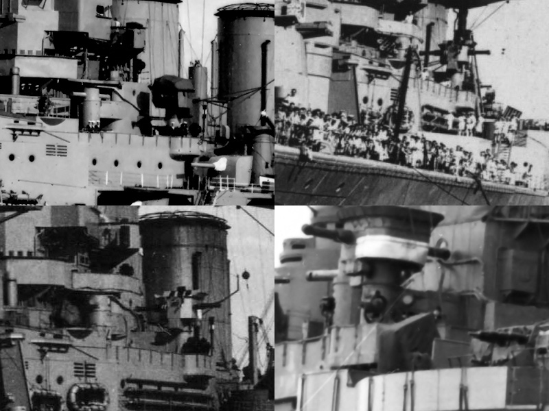
In these four small images support columns appear to be present, well enough to decide to add them to the model. If you have your drawings nearby: the in the bottom-left image is not the officers-of-quarters position (a small position at about the same location ), as this position was removed in 1929-1931.

So, this is what the model looks like below the boat deck.  One of the disadvantages of my model is that the hull is still the old White Ensign Model core. Because I “like” the way the hull looks now and the amount of time invested in it, I decided not to scrap that part. Still, the new styrene decks were added rather amateurishly; glued directly on resin and putty (oh no). Note the patchwork of replacement decks. This looks awful but will be very hard to spot once to model is done. One of the greatest risks is that the bond between the deck and hull will give way and the model is ruined beyond my emotional capacity for recovery. In order to avoid that, the superstructure pieces will not be glued to the deck; note the brass pins; the are drilled into the hull 1 cm deep acting as an anchor to the deck parts. Each brass pin has been tapped with a M1 thread (very carefully!) so that the superstructure parts can be screwed down, all cleverly hidden beneath gun mounts and directors.  Some of the brass pins that remain visible on the model have been fitted with a styrene jacket for easy painting. The thinner support columns were drilled in using the drill press. The deck openings for the stairs going to the lower levels are visible.

Details that are know to be present below decks are the afore-mentioned vents, hatches, wash deck lockers, 4″ ammo lifts, bollards, support pillars, davits and the chutes. The hatch was based on images of a King George V class battleship where the chute is in the open near the aft breakwater. The davits were made in series, four of which are to be placed on the quarterdeck. The four davits I liked least were placed below decks. A slight waste of effort, but nice for this very picture and people taking the time to check if all detail is accounted for. Note that the name place with the text ‘HMS HOOD’ is placed behind the hatches in the bulwark her name can now be found on six places on the model. The bottom-right image shows the cordage reels, the 4″ ammo supply hoist (that is, a bit of styrene strip) and rods leading to the mushroom vents (if you have a vent of deck, the piping has to go somewhere).

Now that most of the hull is complete I decided to add some additional detail: a small line scribed between contiguous armor plates. The artwork by Burt in his battleships books shows these lines and even though they are not very visible on most photographs I decided to add them anyway because it looks rather nice. Now, the lines by Burt prove totally imaginary after cross-referencing them with HMS Hood’s shell extension plan from the National Maritime Museum. It’s just a matter of counting the frame numbers, taking the non-constant frame spacing into account, and a bit of scratching to do. Here the hull problems resurfaced again and many lines required repair and rescratching, including some repair work of the armor belt (plastic) delaminating from the resin hull. Sigh, that was very depressing and it still looks bad. Perhaps I should just paint the model and be done with it. The hatches on the side of the hull were added as were the remains of the davits. These hatches were done twice, because I damaged the hinge system beyond repair during the line scratching.


Booms, davits and derricks, part I

There are many booms, davits, and derricks scattered around HMS Hood’s decks and superstructure. The rigging and davits are drawn up in excellent detail by John Roberts’ Anatomy of the Ship: HMS Hood and Anatomy of the Ship: HMS Dreadnought. A full list of booms and derricks is given in Maurice Northcott’s HMS Hood: Design & Construction (Ensign Special or Man o’War, same content). Together they have nearly all the information we need for the 1941 version. From the images can be concluded that some booms are tapered, but derricks are not. All booms and derricks are wooden, except the main derrick.

Here you can see a paravane being deployed or recovered (A), but this is not the paravane derrick. This derrick is operated next to A turret, while the actual paravane derricks were stored directly aft of the forward breakwater where a pair of paravanes were stored (B). You rarely see these derrick deployed though and if you want to add them the best option is to either model them lowered (C) or not at all (D); Most images of the forward breakwater show the derricks to be absent. So, if you build the Trumpeter kit you’d best throw these parts away.

The second largest set of derricks consists of three pairs of 40ft derricks. These derricks were used to load ammunition or hoist boats. When HMS Hood was completed, one set was stored near the bridge, one set was fitted to the smaller cranes on either side of the funnels, one set was stored at the deck side on either side of the main derrick and one set was stored to the quarterdeck (4 pair). For the 1941 version, two pairs of derricks were fitted to the bridge bulkhead, below the smaller sounding booms, while the other two sets remained fitted to the smaller cranes. The quarterdeck derricks were removed.

Another set are the 36′ 9″ sounding booms. No resource specifically identifies their location, but two booms of the same length were fitted above the 40ft derricks during the final modification. This indicates that the sounding machines themselves were on board when HMS Hood was sunk. The image shows the sounding boom deployed during outfitting (A). Two sets of booms are fitted for embarking and disembarking. One set of 50ft guest warp booms (A) was fitted to the hull near the bridge and one set of 30ft6in swinging booms was fitted at the quarterdeck bulkhead. These booms were all tapered. Note how all these booms were rigged with a stay and two lines.

The swinging boom near the quarterdeck bulkhead is very difficult to spot in photographs taken during the war. The stays are easier to spot (A), even though the boom is not (B). Note that the 40ft ammunition derrick at (C) was removed when the air intake in the quarterdeck bulkhead was covered up (D). The stay for the swinging boom is still present in the image bottom right.

The largest derrick is of course the main derrick operated from the main mast. Here you can seen the main derricks aboard HMS Rodney (left), HMS Inflexible (top right) and HMS Hood (bottom right). The style of the main derrick appears the same for all capital ships and the drawing in the Anatomy of the Ship: HMS Hood is not accurate. There are small changes in the rig of the derrick between ships and the hoist line does not loop back the same number of times for all ships.

The flange couplings of the main derrick were simulated with tiny triangles added with a very fine pair of tweezers. The pully in the end of the derrick was added as well for proper rigging. The start point of the derrick was ‘milled’ into shape with the cross table of the drill press.

The support on the main mast was built from plastic plate; you don’t always need photo-etch to make such difficult to make shapes (even though I should have).

The list comprises of

1 65ft main derrick (1)

2 50ft guest warp booms (2)

2 30ft 6″ swinging booms (3)

4 40ft 4t ammunition derricks (4)

2 40ft 5t boat & ammunition derricks (small cranes) (5)

2 36ft 6in sounding booms (6)

2 12ft paravane derricks, mostly stored

Northcott lists one 8ft derrick present as late as 1931, but I haven’t been able to find any image, so I guess it was stored out of sight with the paravane derricks?

Most work on the derricks was spent adding small rings!

The smaller davits will be treated in a small follow-up post.


Copyright © 2024 On The Slipway

Theme by Anders NorenUp ↑