Continuing from part II.
Because I though it would be fun, I purchased drawings of the quadrupple guns along with the Mk V and MKVIs of the octuple pompoms to make small models to be distributed by any manufacturer. If you have seen the barrels of Master from Poland, you know you are dealing with a manufacturer who’s really committed to accuracy. I asked them if I could trade a few custom barrels for the etch design and a few parts. They said yes! However, having accurate custom made barrels as tiny as a 1:350 40mm gun is great but now my models couldn’t be so awkward that only I can handle them; other people have to be able to make them as well. So, I decided to make a series of prototype guns. One set of three guns is for my own model and will be a set of no-comprise all-singing-all-dancing models. One set of three different guns will be made for Master for casting. One set of two guns will be made as a demonstration showing that all parts—etched or cast—will actually fit. I made a series of parts and the best parts were selected for casting, the worst part was for the test-fit model and the rest are for my models.
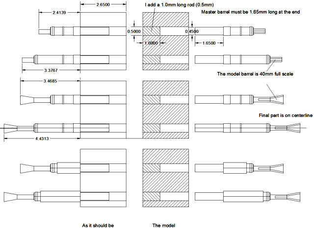
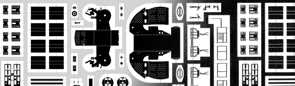
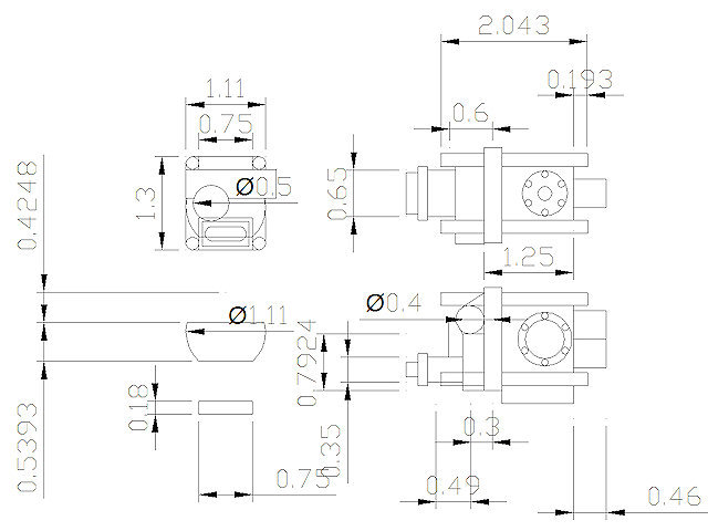
Here’s a production drawing that was sent to Master. The cooling (heating) sleeves around the guns are placed eccentrically but not on the models. A small rod will be placed inside the gun cradle master so that all guns will fit nicely. The bottom drawing shows a version of the gun with additional sleeves (Remote powered versions). Perhaps some drilling is required for the cast parts. Note that both short and long barrels are designed for the inner and outer guns.
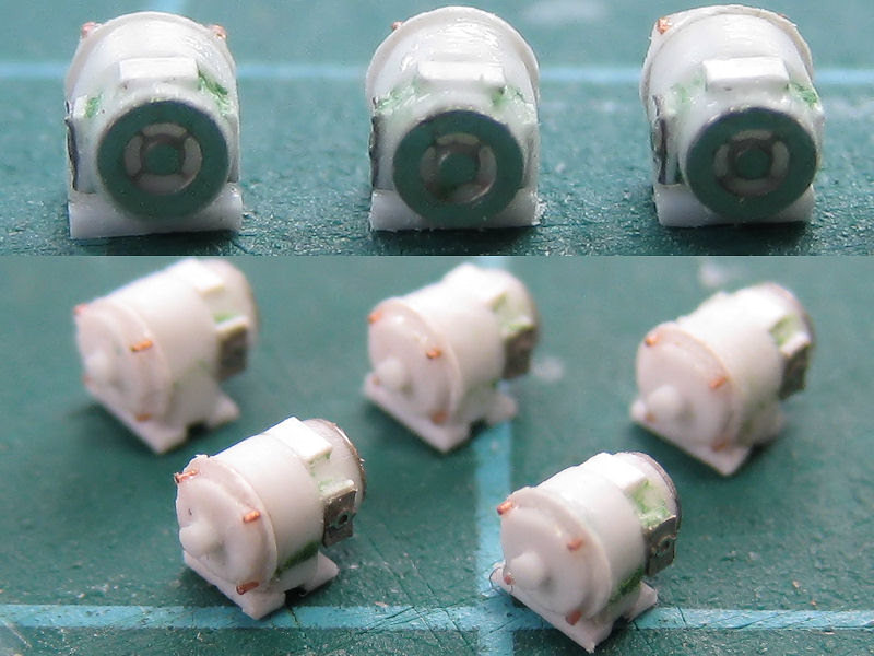
The gun cradle started as one main part with a smaller detailed part glued to its inside. The MASTER model will be a monoblock.
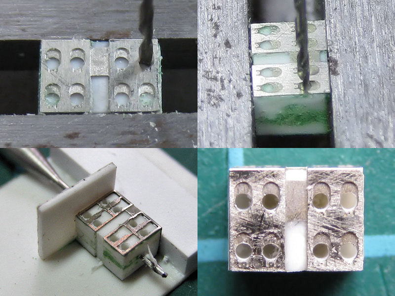
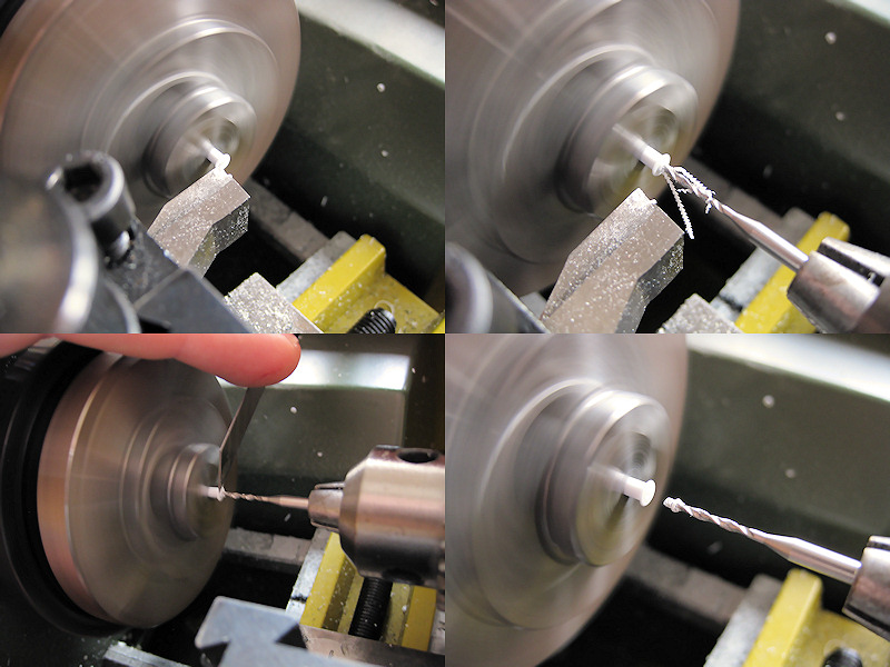
The gun cradle block was drilled through using the drill press. I had to first position the drill and to then take a picture using the macrosetting of the camera to see if the drill was set properly! Perhaps I should buy a visor or magnifying lens?
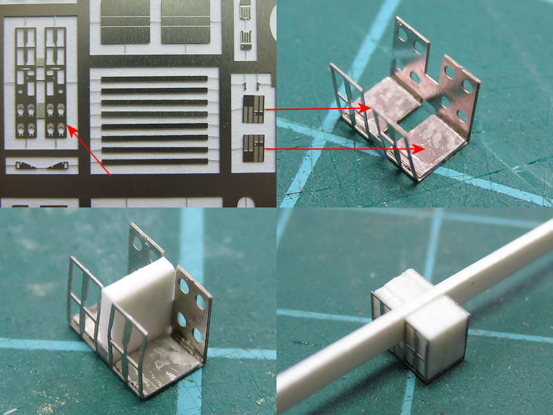
Small detail parts were added to the roof of the gun cradle. I use Tamiya tape to position the part and use a 0,1mm brass wire to apply a drop of glue. The gun cradle of the quadrupple gun is seen at right.
All MASTER gun cradle parts are now complete. The parts are fitted with disks or rods to help aligning them in the main etched parts.
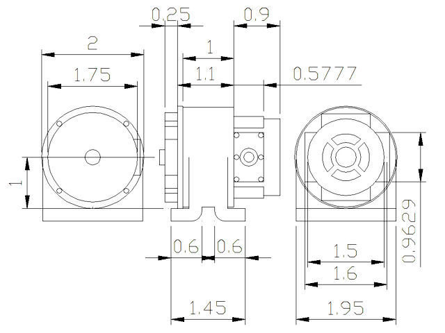
There are two pieces of equipment at the front of the model; an electric motor and the hydraulic pump. Here’s the production drawing for the electric motors. With these small parts, you really have to plan ahead and such CAD drawings are of great help to me.
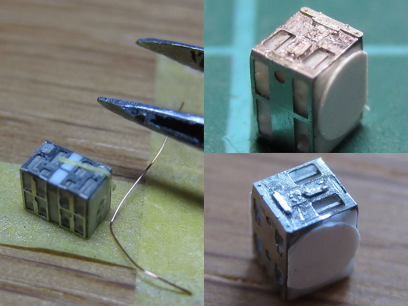
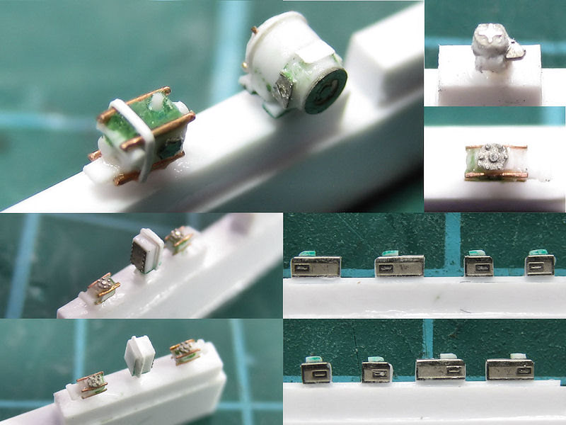
Here are the models of the electric motors situated front left on the model. They are a combination of lathed parts and rings made with the punch & die set (I make all rings on the lathe now, the punch & die is not accurate enough). The brass wire is 0.1 mm thick.
The pump for the hydraulics is on the other side. This part is much more complex than the drive motor. A lot of pipes run from this gear to various points around the weapon. It appears to be an iron cast housing of complex shape. I made an approximation for this part. The final part isn’t really as accurate as the drawing might suggest. This part was so time consuming to make that I decided to make one and cast the rest. Among other small parts I decided to cast are two hydraulic units behind the ammo trays, bolted to the side of the main gun frame.
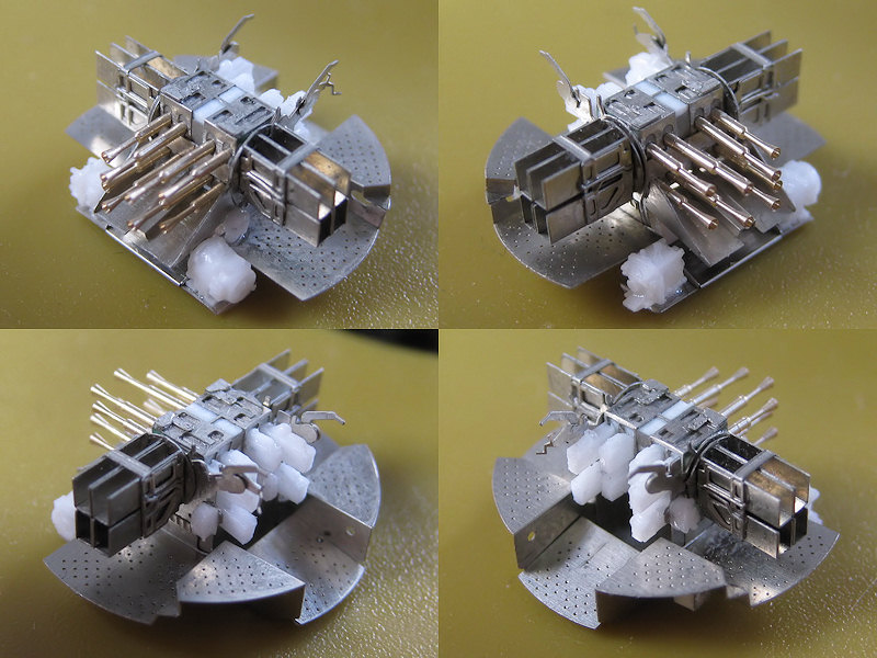
This is an overview of all the parts. The top left part of the image shows the hydraulic pump and drive motor situation at the front of the gun. The image top right shows the elevation drive with one of the hydraulic pumps below it, also shown bottom left. The bottom right image shows the rear of the guns protruding from the rear of the main gun housing.
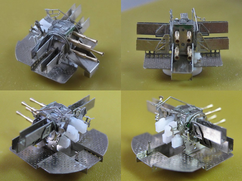
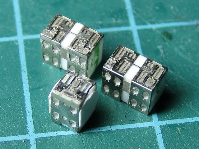
These are the test-fits of the demo models. The parts are assembled a bit wobbly… I was so preoccupied with detailing the modes that I forgot that HMS Hood carried one Mk VI. The main etched part for the gun cradle is now a Mk V but the rest of the parts are not. Complaint forms can be downloaded at the IPMS main website. Anyway, the fit is fine but some parts were very difficult to align. Many of these errors were ironed out for the second design. These etched parts arrived last week.
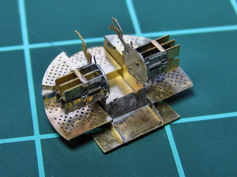
The new design works much better. It’s made from brass so I could finally solder all parts; no glue so far. I have no experience with soldering but you learn a lot in a day. One ammo tray took hours, disassembling itself when re-adding heat; the second one was produced quite quickly. Still, these are very tricky models to make but the results should be well worth the trouble!