Page 16 of 27

Funnels, part I

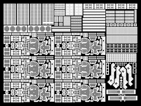
The models for HMS Hood’s funnels were already completed a few years ago and were of the few remaining parts of the first generation. The walkway at the center of the funnel was solid styrene, not a nice new etched walkway and the railings weren’t done so nice. So, I decided to have new parts for the funnel in the etch set for the walkway and the one-bar railing and start all over. Little did I know that these were the parts with the highest failure rate of any sub project I did so far.

This is the only one good shot (known to me) of the funnel interior, taking from high up in the bridge structure. It would have been wonderful if the sailor who took the image would have taken one of the funnel closer to the bridge so that the interior would be fully visible, because almost no other information is to be found. You have to interpret the image careful to distinguish between the railing of the walkway and the vertical and horizontal supporting bars and stays. The first thing to note is that there a walkway going around at the edge (so that the crew can deploy and fix a canvas cover) and a walkway in the ships length direction, but there is no walkway across the funnel in beam direction. Second, note that the (only) walkway across the funnel ends a bit higher at the far than the walkway around the funnel. As the funnel cage is curved, it would make sense for the across walkway to correct for this curvature and be a bit higher so the crew can pull the canvas cover over the grid. These covers are rarely used and are seen mainly when ships are being built or when mothballed

Few drawings of the funnel interiors exist at all but I managed to find two in Anatomy of the Ship (AOTS) Dreadnought and Belfast. This image is from the former source, by John Roberts. Even here it is mentioned that the exact layout is not known and is based on contemporary design. I decided to “create” HMS Hood’s funnels based on this information. You can notice a few things in this wonderful drawing. First, a ladder is seen from deep within the funnel going toward the walkway. The crew had to access the funnel from the upper deck. Now, if you look at the top image, you’ll notice that there’s an opening in the railing of the walkway. Hence, an opening for a ladder must be present for HMS Hood’s funnel as well. So, the shape of the walkway is distinctly different for the walkway as sketched by Roberts in AOTS HMS Hood.

Second, a large number of internal funnel stays are visible. The position of the stays remains unknown, except the two in the top image. Two vertical supports from the funnel cage down to the walkway seem to be at the same position. However, only two supports sound a bit low so I added two additional rows. I cheated a bit, as you cannot see them in the top image, so I decided to let those additional two stays start a row lower down. The stays end above the division plates at the bottom of the funnel. I didn’t add an etched walkway for this funnel interior, as I forgot about it and the previous version of the funnel ended one deck higher on the model so it couldn’t be placed. So, I’ve hacked that part away to show the division plates. Anyway, the design for the educated-guess funnel interior is now done.

A hollow funnel is one thing, but snugly fitting the etched part is something else, so I experimented a bit. I had a mould made from the dimensions of the etched walkway and wrapped it with plastic plate and put it in the oven. I spent a lot of time playing around with the plate thickness, the dimensions to get a good part, the temperature and the heating time. I ended up at 150 degrees (C) for two and a half minutes. The result is a thin 0.25mm plate with the correct shape. A second plate was wrapped around the first one and they were glued together. I had to add a few markers so that the plates were glued in the same position when they were heated, of they might deform the funnel a bit.

The result is a heat-treated funnel that fits the etched part like a glove! (the part in the middle is the antenna for the Type 273 radar and is not part of the funnel).

Adding the stays was the next experiment. I make a small ring from two additional layers of heat-treated plates and drilled in the funnel with a 0.2mm drill. Brass rod was inserted, glued with CA and later trimmed to size. I made several attempts, as a small misalignment of a row of holes showed up only too easily. The rod was added with the funnel on the mould to have something to hold the funnel with, lowering the mould with each successive row.

The result looks quite good, though I had to be careful not to exert too much force bending the brass rod which doesn’t bend back. Corrections can be made, but the results were not always too precise for my taste. So, for my second series (reason for doing so stated below), I tried using fishing wire. A series of channels was carved in the outer plate and the wire was weaved around the funnel. This did solve the problem of a brass wire not being able to stand tension, replaced by a wire that couldn’t take compression. So, I had to use some force pulling the wire taut, and I tore a hole through one of the funnels at the last pass (of course). Not so useful either. Still, all the channels and adding some pretension did work out quite well, so I went back to brass wire.

So I kept the idea for the channels and added some tension by pulling the wire and bending it downwards before trimming it to size. A third layer of styrene was added to bring the funnel to its required thickness before adding the exterior detail: next in line were the rivets on the outside of the funnel.

I already added some rivets to the tops of the main gun turret and decided to continue that technique here. I visited a repair shop for antique clocks and they gave me a collection of very fine gears. I made the tool you see in the picture above.

The plate width required for the funnel was first measured carefully using test plates and divided in strips. Using a table, the caliper, and a ruler, I rolled in line after line of rivet detail.

The result is a nice plate, a bit over-scale, but the effect should be worth it.

Adding the plate proved to be quite troublesome, as you cannot use normal glue as that will melt the thin plate and using superglue leaves very little room for error. Here can see the test fits of the plates (I had only half the rivets on the left funnel, so it was replaced).

The problem with the first set of funnels was that I accidentally removed a bit of rivet detail. The split between the plate ends is cleverly hidden behind steam pipes, but still, people may want to go searching for errors for the funnels just to see if there’s a plate line and spot the ugly area. I tried to repair this part by cutting out a part of the riveted sheet and add some replacement sheet, making matters much worse! These funnels were trashed, something I learned to regret later on, as these funnels were really a lot of work.

So here are the last versions of the funnels. I didn’t manage to have the horizontal bolt lines align properly for both funnels. Gluing was quite tricky, as the plate needs to be aligned properly and the smallest deviation will show up. Work to fast and you can make an error. Work to slow and the glue may form lumps that will show up immediately and you need to carve off the plating and clean the funnel (another hour or two). The split is filled and looks reasonably fine on a close-up and it’s tricky not to damage the lines of bolts on either side of the gap. Do note that the spacing between rivet lines along the split matches the distance between other lines quite well (hurray for planning ahead). Fortunately the double steam pipes, one set per funnel both over the split, will run over the horizontal lines.

Here you can see a collection of the failures.

Cordage and Hawser reels, Part I

One of the reasons this blog wasn’t updated for a quarter of a year was due to the trouble I had with assembling the cordage and hawser reels. I’ve split up the posts into two parts: standing and hanging reels. The latter are the thinner reels that are scattered around HMS Hood hanging from a bulkhead (about fifteen) plus the four smaller reels near the davits of the 27″ whalers. Here I’ll show the standing hawser and cordage reels, otherwise known as the opening scene of “how I started worrying and learned to hate my model”.

One of the things that will immediately become apparent when you start looking for photographs is that the reels are nearly always covered in canvas (just as the ships boats). Although I want to have the most accurate model I can build, I already decided to slightly cheat on those covers so that all detail would be there to admire. Using the images that I had, I started with a head count. This is quite difficult, as you need to determine the height of each reel correctly before you can decide what type it is, or perhaps you find out it is a type you missed? I certainly wouldn’t recommend estimating the type by eye, I really needed a ruler the estimate the dimensions in relation to items in each photograph.

I’ve identified five types. The first type is the large hawser reel (L) that is specified in the Anatomy of the Ship series volume (but not entirely to my liking). I found one behind the forward breakwater, two on either side of the aft searchlight platform, and one next to the bridge (see below).

Other types are seen here. The top right one is a cordage reel that remained on board HMS Hood, but I cannot find more that one, at the starboard side of the forward funnel. The bottom-left is a hawser reel that is similar to the largest hawser reel but smaller, about the height of the railing (hence medium). I found six so far: one behind the forward breakwater, two behind B-barbette, two in front of the main stairs on the boat deck (between and outboard of the funnels), one near the main mast. I also had a look at the image top left and decided this cordage had a few weight-saving holes. This is not uncommon so I made a variant on the medium hawser reel. I now think it’s just a normal cordage as the one top right and the image is too poor to make out its correct configuration. Still, these variants were added anyway. We know that many cordage reels were replaced by hawser reels so this one will be a hawser reel too. The last type is a hawser reel shown bottom left that is basically too small to be a medium hawser reel (so: small). There are four: two are fitted below the paravanes stored on either side of the bridge (lots of smaller reels are fitted there as well), and two were found at the far end of the boat deck, both at port side.

This image shows two small and one large reels at the far end of the boat deck. The right vent and 4″ mount serves as a reference for identifying them.

This image shows a nice surprise: there is a large hawser reel (taller than the railing) fitted near the bridge. There are no other images of this reel, so it’s quite difficult to make out its position.

The dimensions were obtained from careful observation, but the pattern followed from tracing existing reels from museum ships. This image was taken of HMS Haida, taken from Resin Shipyards, with permission. The design matches the drawing in Anatomy of the Ship and required dimensions nicely.

The other reels were drawn using what material I had. In order not too have too few details on these parts—can’t have that—I decided that each side of the reel should consist of three parts, as shown here. There are a few design choices I made that seemed like a wonderful idea but turned out to be quite to opposite. The center part would first be glued to the large part, by applying glue from behind. The combined parts would then be centered on a small drill and the last part would be added, nicely centered. I started with the largest reels, thinking them easiest to construct but they were the hardest to do by far. Notice that the center etch part has a small circle that fits nicely on the part at right? These need to be aligned. This was the first major error: it is so very difficult to apply glue while keeping the parts aligned. I’ll make sure to avoid breaking rotational symmetry of the parts when I can help it.

But this was only the beginning of my troubles. The parts are etched in steel—not brass—that material is very difficult to glue. All parts kept falling apart and proved to be very difficult to glue back without overdoing the glue or damaging the parts. I had to try out all different types of glue before deciding on one glue that worked quite well: a good bond, not too thick, not too expensive and easy to apply. I now use ordinary Pattex. I trashed all my other super glues and I won’t be buying these miracle glues on modeling shows as they clearly suck (no, the glues!). The Pattex won’t last very long when opened, so I bought many bottles. I also learned that flat PE parts squeeze most glue to the edges, so very little glue is actually between the parts. Removing excess glue usually results in not having any glue at all. Next time I’ll etch some ridges to keep the glue where it is supposed to go.

After having solved the 2010 glue crisis, I made the drums. Simple rod with a 0.3mm hole in the center. I used thin brass wire, set my lathe to the slowest setting, and applied a bit of glue. Turn on the lathe, and see how wonderful the wire will wind itself into impossible shapes and how the glue will get everywhere and forcing you to start all over. Again! Needless to say, I had a lot of failed parts. The next problem presented itself when you find out that you need to trim the drums to length so that the edges are perpendicular to the center line; otherwise these nice etched parts will be skewed and all effort was for nothing. Of course, when the bond of previously-etched parts wasn’t as good as you hoped for, the entire part could come loose at the last minute anyway. So, at the end of the construction phase, a small round of non-destructive testing was introduced to sift the strong from the weak parts. Those who could be saved went to the depressingly small pile of finished parts.

Here they are. Nineteen small models (short of one large reel). You’ll notice that the etch set, which I had made three times, has enough parts to make ninety (link). I thought I had enough parts to make lots and lots of parts and worry about how many I needed later. “I can always choose the ones that worked out best”. Unfortunately, I hardly have spare parts left! I have one spare cordage and four medium cordage reels that are probably wrong anyway. Still, I really like the those small holes and I think I’ll scatted them around the forward gun turrets.

So, on to the really small hawser reels. The good news is: only two etched part per reel and not six.

Happy ending in part II

Winches, Part I

Two types if winches were present, the variable speed winch (VSM) and the electric winch (EW). These winches are scattered mainly around the barbettes and the forward boat deck area for the boat derricks.

The above image shows HMS Hood shortly after her construction with both types of winch clearly visible. There are two VSWs between the forward and aft turret pairs plus two more on the starboard quarterdeck . Two EWs are placed at B-barbette, two on either side on the conning tower, two near the boat derricks, and two against the quarterdeck bulkhead. The winches near the turrets aren’t positioned symmetrically, so not all winches are shown on the above photograph.

If you look very closely, you’ll notice that the rigging of the boat cranes was changes at the end of Hoods career. Two winches were placed on the structure between the funnels as indicated above (reconstructed winch shown). All (most?) references indicate these winches are the same winches as previously placed on deck level but changed position. But then there would be no winch to drive the derrick, only the hook, and the rigging scheme no longer makes sense: these have to be new winches to operate the derricks. Images showing both in a single shot weren’t found.

The evidence is really staring you in the face if you look closely at the above photograph from the official HMS Hood site of these two sailors posing in front of the boat derrick’s EW. The 16″dinghy stowed to the bulkhead and the 25″ fast motor boat indicate this picture was taken after the winches were placed between the funnels and yet a winch remains visible. So, the number of EWs was increased to ten, though only eight models are required.

The left half of the image shows how the rigging of the boat derricks was lead to these new winches. The right half of the image shows that the two EWs on the quarterdeck were later moved inside and only the drums remain visible. No small wonder, considering that Hoods quarterdeck was always flooded when underway. Having the winches inside isn’t new, all the Queen Elizabeth battleships have their winches inside.

After having done a thorough head counter the two types of winches were traced using a CAD program. Some perspective is always present but they should be reasonably accurate. The VSWs still remain a bit of a guess though.

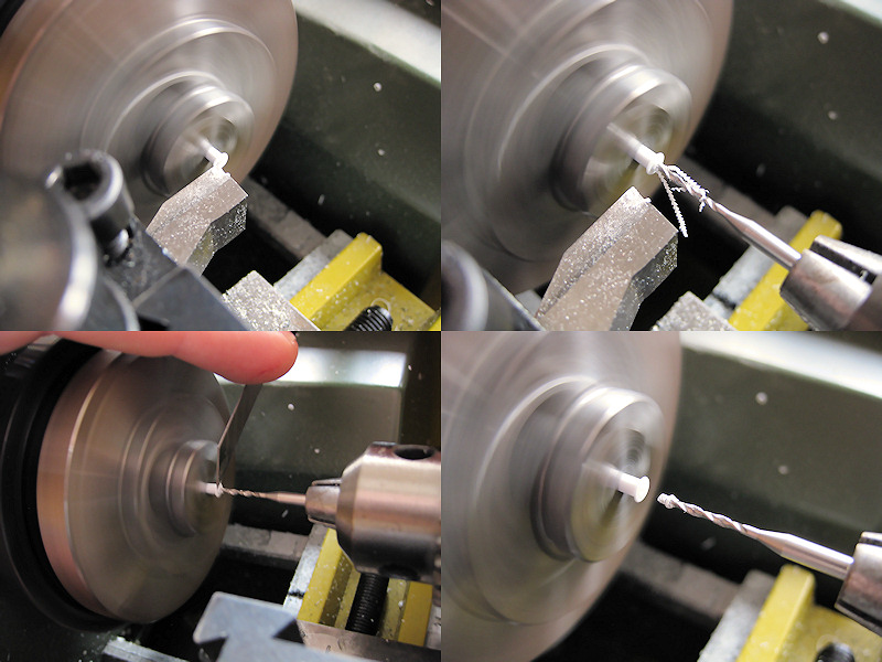
The main difficulty in making the winches are the drums. I spent many hours trying the get the lathe to do what I wanted and made many failed attempts. The drum was made from brass stock. made flush and the center was marked. A 1.0mm hole was drilled in next. The lathe was set to make a tube with a wall thickness of 0.1mm. The lathe was set at its maximum rpm.

The tube was parted from the stock brass using a parting tool bought from MicroMark and ground to a 0.4mm width as visible top left. Note I use the drill to support to tube while parting. Although I broke a few drills while experimenting (parting tool not set at the correct height), there really was no way to get a good tube without supporting it, otherwise the lathe tears the tube from the rod. This exercise was repeated for the styrene insert, drilled in with a 0.4mm drill, cut to size and fitted with stock styrene rod.

The next part proved to be very troublesome: I wanted to have 5 holes in the drum, spaced out at 72 degrees. I initially glued the brass tube to stock styrene by Plastruct, but small deviations in its roundness made this a futile effort. The rod was simply not accurate enough and I spent many hours and breaking many drills getting the part right. When using rod made to size with the lathe, I had no such problems and the five holes could be drilled in. I set the drill press to a high rpm and mounted the drum on the divider (Proxxon). You have to be really careful here, as the drill can occasionally push the styrene our and you can also crush the drum with ease in the chuck. Of course, this happened a few times.

Eight drums are now sitting comfortably in the EWs. The winches are built from mainly lathed parts.

Here you can see the completed EWs, with the etched parts for the control box and the some hand wheels. A nice exercise in getting to know the lathe better.

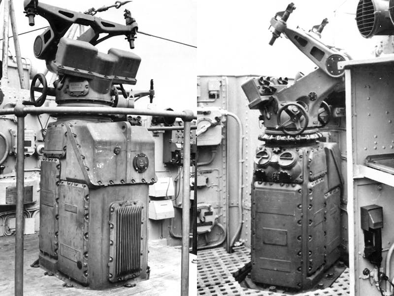
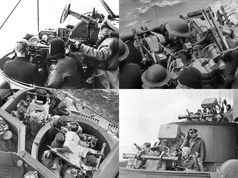
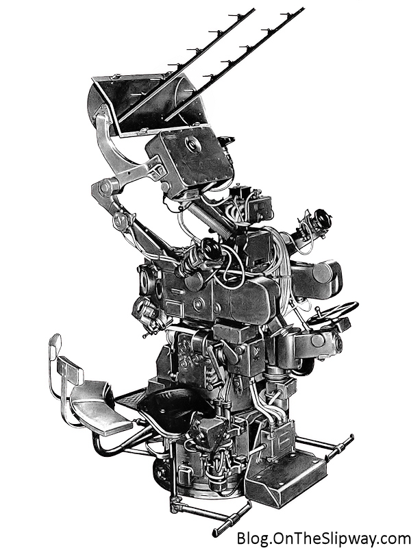
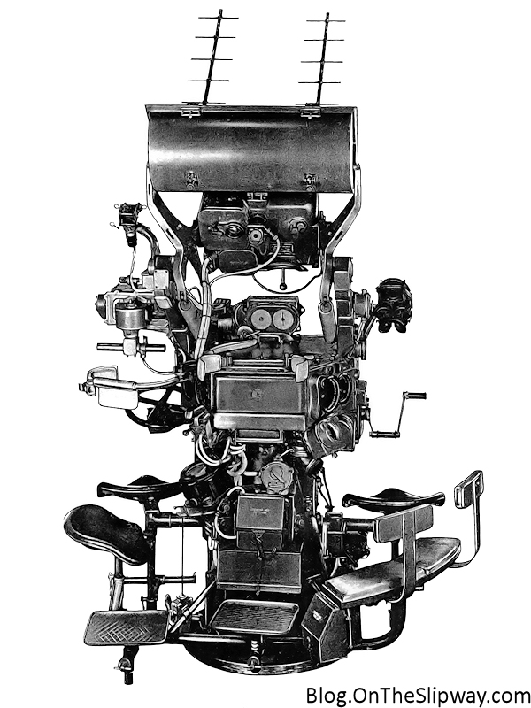
Octuple pompoms, part II

Continuing from part I where I showed the etch design for the new octuple pompoms. I published only the Mk V, but I was working on three models: the pompom guns in question are the octuple Mk V and Mk VI and the quad Mk VII.

The Mk V gun is the prewar version (then called the Mk M, M for multiple) first fitted to HMSs Valiant, Nelson, Rodney, Hood, Furious, Royal Sovereign and Renown. The Mk VI, fitted in 1934 and onward, is nearly the same with minor differences in the platform and gun cradle (central weapon housing). Several capital ships were fitted with one or two of either type, although a shortage of the guns meant that Renown and Valiant initially received only one. Both types were later updated to automated fire resulting in the Mk VA and Mk VIA. Guns designated with a * behind their Mark denote a weapon fitted with guns firing a shell at a higher muzzle velocity. Later versions were remote powered denoted RP10, RP11 and RP50. Most ships were fitted with a mix of versions of both Mks or remote power units. The Mk VII is the quadruple version with again many variants, e.g., the Mk VII*P being the high muzzle-velocity self-contained power mounting. The late war version of both the octuple (Mk VIA* rpxx with the aft part of the mount fully enclosed by shielding) and quad guns (Mk VII P*) are much more complicated to make and are a completely different weapon to model. Of course, John Lambert drawings has all of them but you have to stop somewhere. The differences between the Mk V and Mk VI are slight but as HMS Hood has two Mk Vs and one Mk VI (on the bandstand just behind X-turret) I wanted to have both correctly modeled. I currently do not know for sure how to distinguish between the normal and automatic (A) fire guns or high-velocity versions, but I suspect that the (conical) flash suppressor is typical for the automatic version? Most ships were upgraded to these types of barrel at some point in their life.

I have prepared a few images showing the early/mid war versions of the weapon and how to recognize them.

This is an excellent image of a Mk M or Mk V aboard HMS Rodney, taken from Man O’War 3 (1979) by Raven & Roberts. Note the small ‘hatch’ on top of the gun cradle. This is typical for the Mk V. No flash suppressors are seen on this weapon. It appears that the gun sites are already the more modern version than those on the Mk M. Note the two sailors loading the ammunition.

The Mk VIA* is the gun you’ll see on most ships, here aboard HMS Prince of Wales taken from Ensign 1 (1972) by Raven. Note the structure on top of the gun cradle is different and two ridges are visible. This weapon was fitted with flash suppressors at the end of the gun barrels. The early ships of the King George V class were delivered with these weapons, later expanded to as much as eight octuple mountings. Note that the gun sights are the sights as in most photo-etch detail sets, but that these sights do not appear on early versions of the pompoms.

This is an image of a pompom Mk VA* aboard HMS Nelson or Rodney (forgot source). Note the small hatch on the gun cradle in combination of the flash suppressors at the end of the gun barrels, so we can be sure this is a Mk V, not a Mk VI. After both Rodney and Nelson were fitted with more pompoms near their secondary battery, quarterdeck and B-turret (Mk VIA), it appears that the older Mk V weapons received new guns (or were upgraded to version *). Pictures of both battleships—and many others—after fitting the additional modern pom poms show the barrels with the flash suppressors.

This image shows Mk VIs prior to 1939 without the flash suppressors. Images of this version are a bit harder to find. Note the ridges on top of the gun cradle. The top of the image is part of a photograph taken on board HMS Ark Royal from British Battleships of World War Two (1976) by Raven & Roberts; the two lower images were taken aboard HMS Hood with permission from the official HMS Hood site. Again, the ridge on top of the gun cradle is visible. Note that the weapon was not fitted with flash suppressors at the end of the gun barrels, so those suppressors clearly do not give away the type of mounting version.

This pom pom has water cooling jackets around the barrels, indicative of it being an RSP mount. Note the splinter shielding on the aft platform of the weapon. HMSs Howe and Anson were fitted with these modern variants. This image is reproduced with permission from Maritime Quest.

I made a small list of what battleship was fitted with what type of weapon and if they were fitted with or without the flash suppressors (new barrels) so you know what gun to place on what ship. This list is based mostly on Raven & Roberts British Battleships of World War Two, one of the few references that state what weapon was fitted, though not in full detail for each ship. The list is complemented and corrected by observation of what pics I could find that clearly show the type of barrel and/or type. It’s not always clear if, for example, if HMS Valiant and HMS Queen Elizabeth retained their older pompoms after their refit, as with HMS Rodney and HMS Nelson, or received all-new units as with HMS Renown. I’ll try to keep this list updated when necessary.

LIST OF GUNS
Last update: June 2010.

*    New barrel with conical flash supressor

HMS Queen Elizabeth
1936 2x Mk VI
1941 4 x Mk VI*A
HMS Valiant
1930 1 x Mk V (starboard only)
1932 2 x Mk V
1941 4 x Mk VI*A
HMS Barham
1934 2 x Mk VI
1941 4 x Mk VI*
HMS Warspite
1934-36 1 x Mk V , 1 x Mk VI
1937 1 x Mk V , 3 x Mk VI (4 x Mk VI*?, new barrels)
Images taken in 1937 show old barrels, but new barrels in 1943. Replaced during the refit in 1942? All units replaced?
1941 1 x Mk *V , 3 x Mk V*I
HMS Malaya
??? 1 x Mk V, 1 x Mk VI
1941 1 x Mk V*, 3 x Mk VI*

HMS Hood
1931 2 x Mk M
1938 2 x Mk M, 1 x Mk VI

HMS Renown
1932 1 x Mk V (port side not fitted)
1936 1 x Mk V, 1 x Mk VI
1939 3 x Mk VI*A (all replaced)

HMS Repulse
1934 2 x Mk VI
1940 3 x Mk VI

HMS Rodney
1932/33 2 x Mk V Abreast forward side funnel
1938 2 x Mk V, 1 Mk VI*A (aft deck)

This image taken in October 1940 shows the new type of barrel aboard HMS Rodney. Image from the Imperial War Museum Collections Online Database.
1941 2 x Mk V*, 3x Mk VI* (one on aft deck) 1 Mk VII* on B-turret

HMS Nelson
1934 2 x Mk V Abreast forward side funnel
1940 3 x Mk V (one on Q-deck), + 2 x Mk VI (in place of secondary director-control tower)
1941-1942 3 x Mk V*, 2 x Mk VI* + 1 Mk VI* on B-turret (6)

HMS Resolution
1936 2 x Mk V/VI?
1941 2 x Mk V/VI* , 2 x Mk VI*I (B-turret, Q-deck)

This image of HMS Resolution from the HMS Resolution association shows new barrels for the quadruple pompoms.
HMS Revenge
1931 1 x Mk V (starboard only)
1939 1 x Mk V, 1 x Mk V/VI (type not know, probably Mk VI)
1941 1 x Mk V*, 1 x Mk V/VI*?, 2 x Mk VII* (B-turret, X-turrets)
HMS Royal Oak
1934 2 x Mk VI
HMS Royal Sovereign
1932 2 x Mk V
1942 2 x Mk V*, 2 x Mk VII* (B-turret, X-turret,)
HMS Ramillies
1934 2 x Mk VI
1941 2 x Mk VI*, 2 x Mk VII* (B-turret, X-turret)

This image from 1944 is reproduced with permission by Mick French & the HMS Ramillies Association, showing new barrels on the excentrically placed quad pompoms.

King George V class
All ships had the Mk VI or later with the new barrel
HMS King George V
1940 4 x Mk VI*
1941 5 x Mk VI*, 1 x Mk VII* (Y-turret)
1944 8 x Mk VI*
HMS Prince of Wales
1941 March 4 x Mk VI*
1941 July 5 x Mk VI*, 1 x Mk VII*

This image taken during the Atlantic Charter clearly shows that a quad pompom was fitted to HMS Prince of Wales’ Y-turret, still present on images taken as late as December 1941; she never carried an octuple pompom in this location. (courtesy of the United Nations

HMS Duke of York
6 x Mk VI*
1946 8 x Mk V*I, 6 x Mk VII*
HMS Anson
1942 6 x Mk VI* RSP?
1944 8 x Mk VI* RSP?, 4 x MK VII*
HMS Howe
1942 6 x Mk VI* RSP?
1944 8 x Mk VI* RSP?,
1945 8 x Mk VI* RSP?, 6 x Mk VII*

Copyright © 2024 On The Slipway

Theme by Anders NorenUp ↑