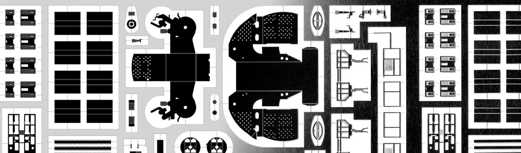
The etch set presented in Custom Photoetch Set Part II is now done. There was a slight delay as the set received some minor adjustments as required by the etcher and I felt I could add one more part (Type 279 aerial). The set was etched by Saemann Ätztechnik in Germany, with excellent results:
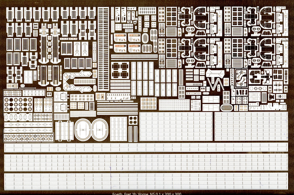
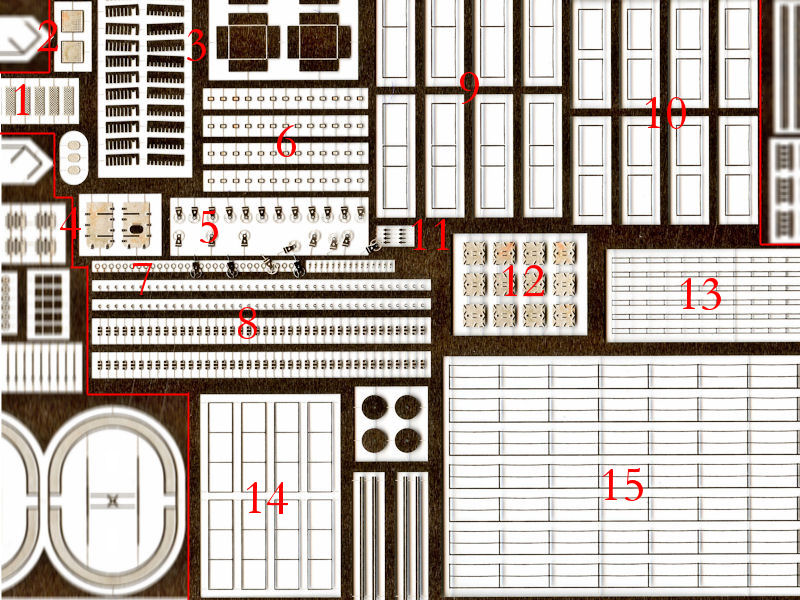
I had three copies made. I decided to spread around the parts so that I would need at least two sets with one for backup. This was probably a good decision; the parts are already falling out of the set as the material holding them in place was designed a bit too thin. An overview with most of the parts is below. The color is a bit off; the material is silvery in appearance.
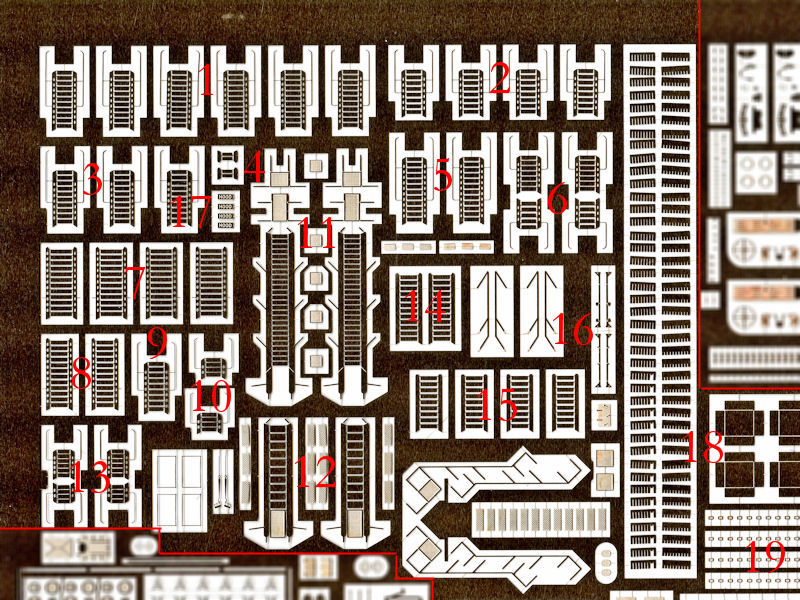
All stairs from the previous set were repeated; I made a design error and couldn’t fold the steps without breaking them. This is now solved. Each deck has stairs etched to size to account for the different deck heights. The spacing between the steps was changed accordingly, so you shouldn’t be able to notice the slight variations in height and span. The model will depict HMS Hood just under way, so the accommodation ladders and stairs on the quarterdeck will be stored.
1 Shelter deck of signal platform
2 Signal platform to conning tower platform
3 Conning tower platform to Admiral’s bridge (large)
4 Behind torpedo control position
5 Admiral’s bridge to fore bridge (direct)
6 Admiral’s bridge to fore bridge (via upper plotting position)
7 Forecastle deck to shelterdeck (wide, outboard)
8 Forecastle deck to shelterdeck (narrow, on centerline)
9 Conning tower platform to Admiral’s bridge (small)
10 Air defense platform to roof torpedo control position
11 Accommodation ladder, shelterdeck
12 Admiral’s accommodation ladder, quarterdeck
13 Fore bridge to compass platform
14 Forecastle deck to shelterdeck (forward)
15 Quarterdeck to shelterdeck
16 Quarterdeck stair platform (stowed version)
17 Foot plates with “Hood”, (Checkered foot plates around 12)
18 Flag lockers, grid plus cabinet
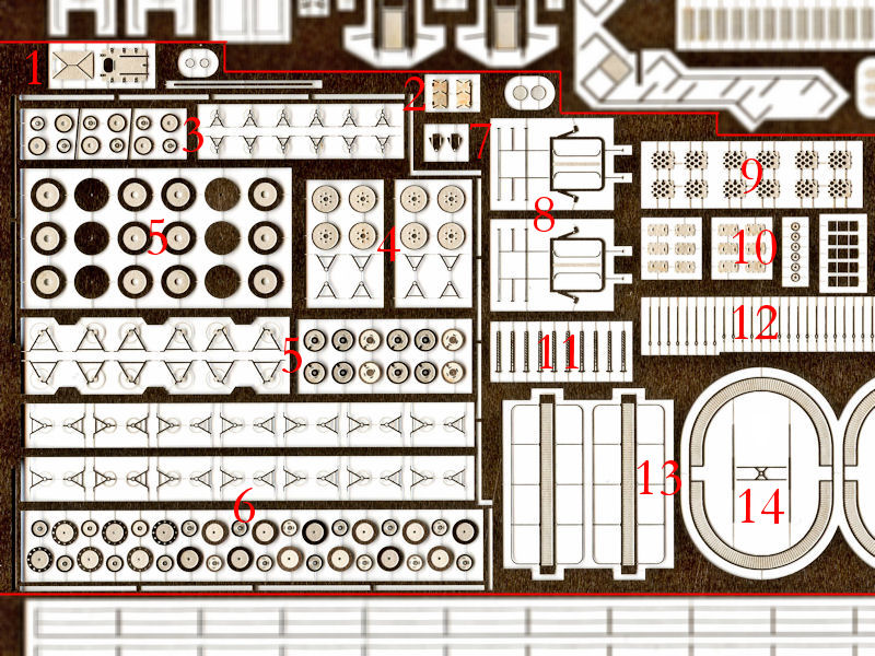
A large selection of cordage reels is included. I found 5 different types and designed them based on photographs on board HMS Hood, and various museum ships.
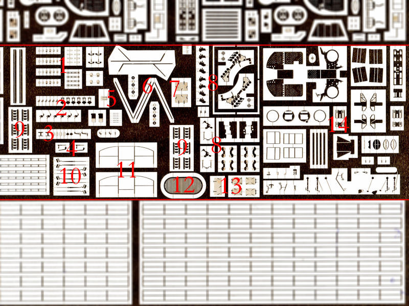
1 New Quarterdeck hatch aft of Y-turret
2 Hatches for cabinet on main starfish
3 Small cordage reels
4 Medium cordage reeks
5 Very large cordage reels
6 Large cordage reels (two styles)
(Very small cordage reels places elsewhere)
7 Detail for X-turret and 20″ signal light detail
8 Night life buoy (repeat)
9 UP ammo locker hatches (repeat)
10 Assorted detail for electrical winches
11 Semaphores
12 Rigging detail (repeat)
13 Funnel walkways
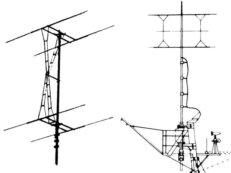
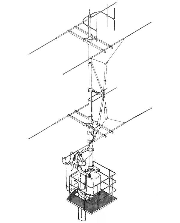
14 Type 279 radar aerial
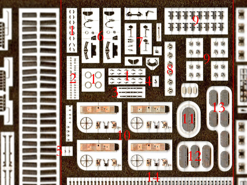
1 Detail for main derrick
2 Assorted eyelets for all derricks
3 Main derrick pulley frames
4 Crane hook main derrick
5 Crane hook small derrick
6 Assorted detail paravanes
7 Assorted detail Pompom director Mk II
8 Escape manhole hatch (omitted in previous set)
9 Assorted detail 4″ gun fuse setters
10 Searchlight lanterns
11 Carley float type 17, 8×12 ft
12 Carley float type 20, 5×10 ft
13 Carley float type 19, 5×8 ft
14 Davit detail
1 Checkered foot plates
2 Small outboard platform of forecastle deck
3 Flag lockers, grid plus cabinet
4 New torpedo hatch (near forward breakwater)
5 Very small cordage reels (not fixed properly)
6 Very small mushroom vents grid
7 Assorted eyelets
8 Awning detail (perhaps too small)
9 Railing around staircases, one end open
10 Railing around staircases, both ends open
11 Torpedo head hatch hinge (on the side of the hull)
12 Hatches ammo storage on shelterdeck
13 Railing around searchlight positions
14 Railing for funnel walkway
15 Railing superstructure (chain)
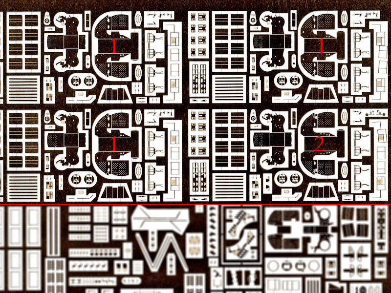
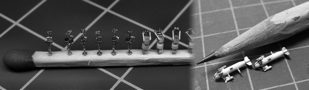
1 Assorted detail octuple Pompom Mk V
2 Assorted detail octuple Pompom Mk VI
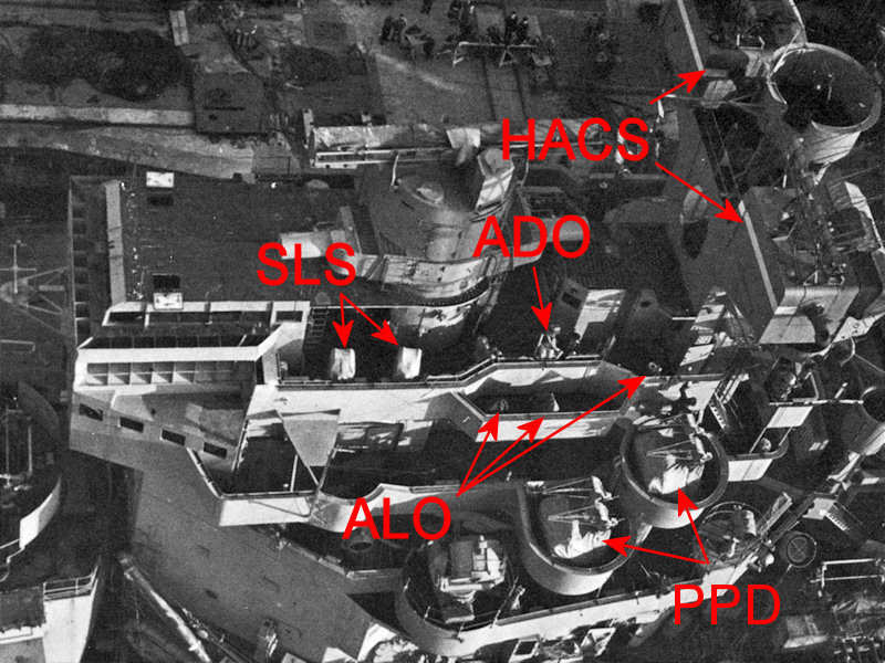
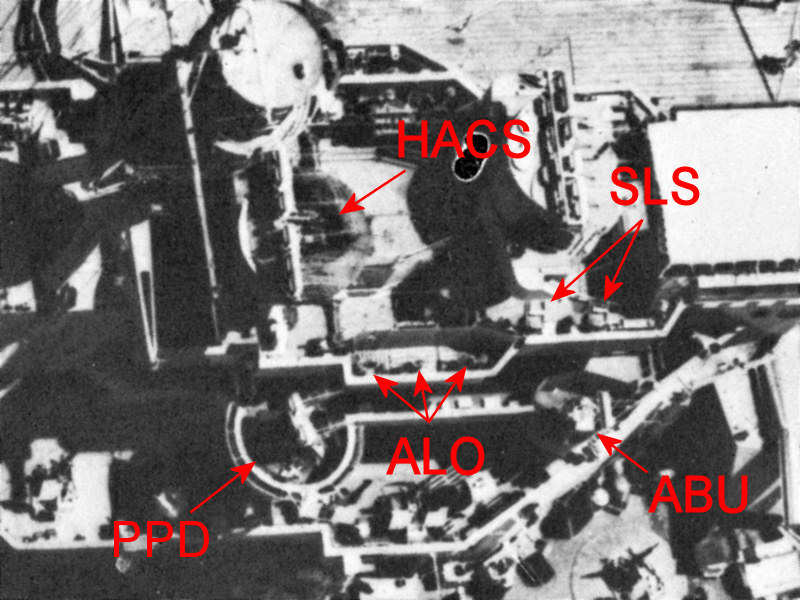
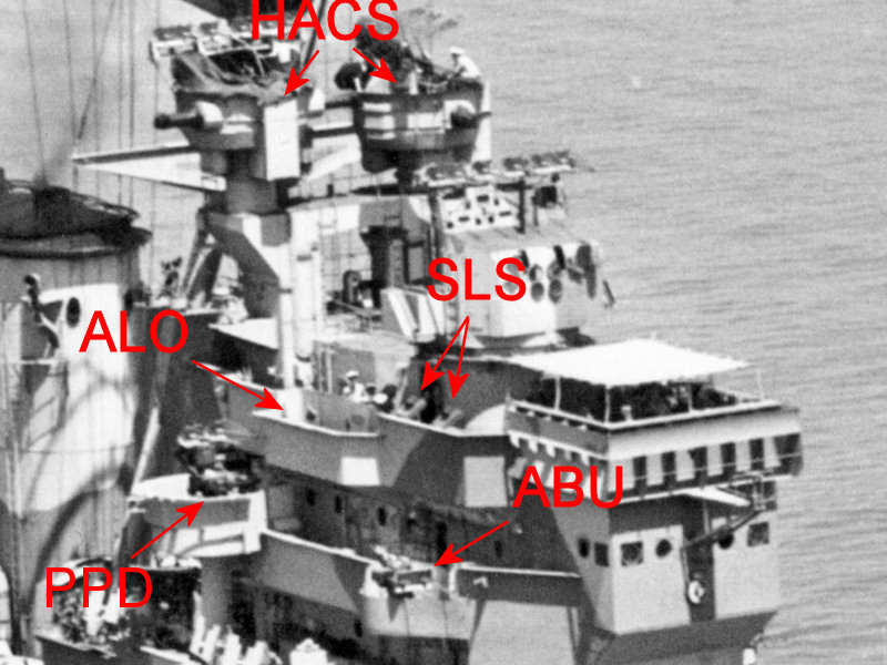
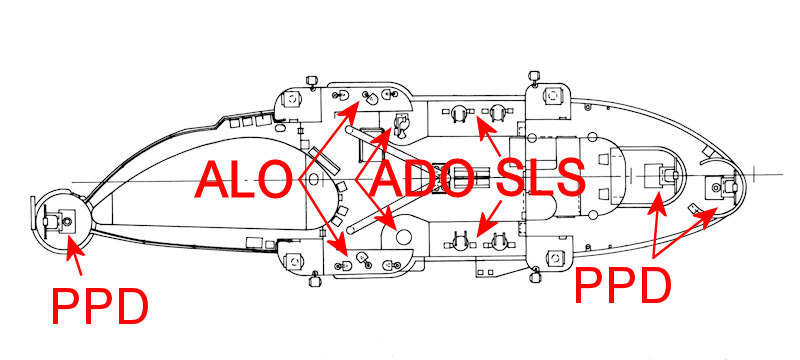
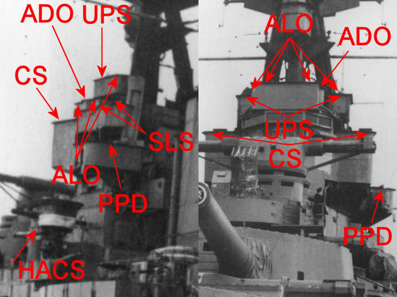
1 Assorted detail searchlight director
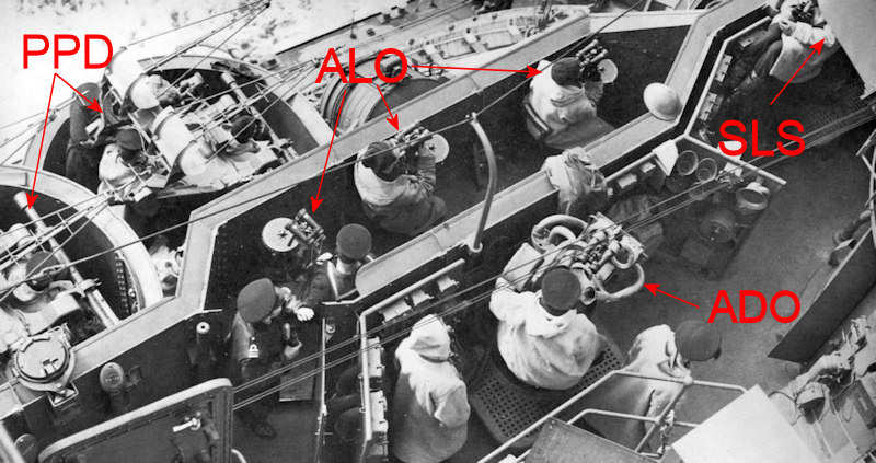
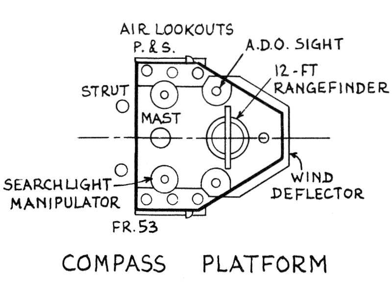
2 Assorted detail air-lookout position
3 Assorted detail air-defense officer’s sight
4 Assorted detail Pompom director Mk I
5 New hatch capstan engine room (near anchors)
6 Aerials MF/DF office
7 Hatch
8 Vickers quad machine gun (repeat)
9 35ft fast motor boat ladders (accidentally added twice)
10 Main mast stays
11 Hatch cover frame
12 Hawse pipe cover
13 Hatches
14 Quad Pompom
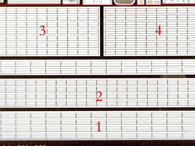
I decided not to use any commercial railing, as HMS Hood has five styles I wanted to have correctly modeled (one being for the funnel walkway). Note that the railing style on the main deck is a wide three-bar , while it has a shorter spacing between stanchions on the shelterdeck. The rest of the railing on HMS Hood is all two-bar except for the funnel walkway. Having two-bar railing above the shelterdeck is a detail missed by most modelers.
1 Railing quarterdeck and forecastle deck
2 Railing shelterdeck
3 Railing superstructure (chain)
3 Railing superstructure (bar)