
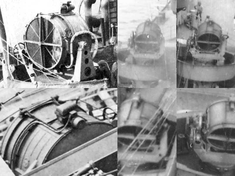
The large 44″ searchlights of HMS Hood were one of the last items of which I did not have good information except for a few pictures. Fortunately, John Lambert issued a series of drawings, L/O/162, although he mentions it’s the Mk VII of 1942-44, while Hood was sunk in 1941. I ordered them anyway and initially thought they were wrong as the frame didn’t match the photographs. However, I found out that nearly all pictures of the searchlights showed their port side and that I somehow thought the unit was symmetrical. On closer inspection it seems the drawing of the searchlights is as good a match as far as I can tell. This picture shows some of the best images of the searchlight. The images at left ware taken of HMS Onslow (top) and HMS Prince of Wales (bottom) with HMS Hood at right.
I intend to build the searchlights in two parts. The frame is mainly built in styrene (can’t see how to make a photoetch part that I can physically fold into the frame shape) and the projector itself mainly as a photoetched part.
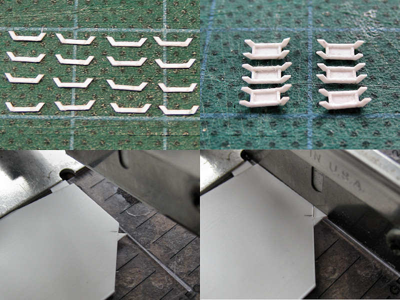
I started with strips cut to shape for the frame and gluing them into the shape shown right. The front and rear should angle back about 8 degrees and this first attempt resulted in very uneven parts. It’s not so well visible in this particular picture but when continuing to add the rest of the frame, the part didn’t really work out. On to the Mk II miniature frame! This time, I spent some more time pondering and I eventually took a slightly different approach by cutting triangles first. At the bottom the mould for the chopper is shown. I use this approach a lot to cut angled parts to size. At right you can see a small template triangle in place to position the template. After a few sizes of triangle, you end up with the size you need (there’s always a slight difference in the template and copy size, usually about 0.1 mm.
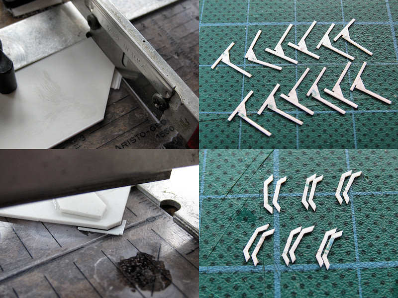
Top left shows how to prepare large amounts of strip at an angle. Works pretty well, but right shows the easier approach; strips glued to the triangles. Now it’s just a matter of chopping the parts to size using another small mould. I always have large cheap styrene sheets laying nearby to spend on such actions. Two chops later and the front and rear base frames are cut to size much more consistently (and easier) than adding strips cut to size.
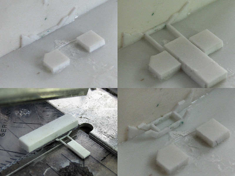
The next mould is a small plate angled forward 8 degrees and placeholder strips for the frame. The two blocks are for positioning what’s shown at right; two strips glued to a center block that acts as a spacer (and makes it easier to handle as well). Add a bit of glue and it’s fixed. Next, the part is cut to size and the same mould is used to glue the second frame. All parts were given some superglue in the corners. Now both the front and end plate are at the correct angle. Using a few moulds seems to be a lot of work but in the end the result was less work, resulted in less rejected parts and the parts more consistent in shape than when not using the moulds.

The top half of the frame was built from strip drilled in using my new drill press which I bought for the occasion. The side detail was built from a small ring, a small tube and some triangles.

This part was sanded to size and added to the frame. I made another ring for the searchlight bearing and checked if the part was nicely aligned. The hand wheel was then added, starting from a strip drilled in with a small 0.3 mm drill using the drill press. I start using thicker and slow-curing CA more frequently when bonding metals as the photoetch parts do not allow most of the other glues I have to stick.
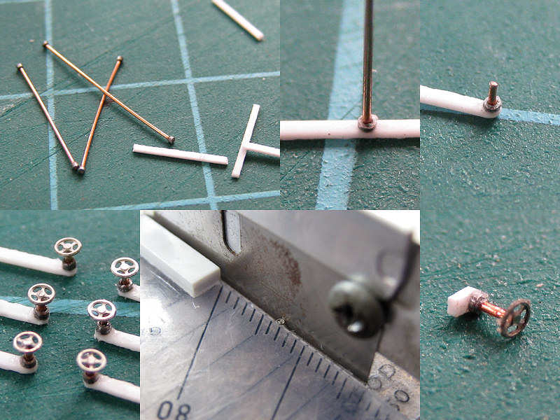
The second hand wheel is being constructed from a small ring and strip. It barely survives the chopper! The end result is a small part to be added to the searchlight base.
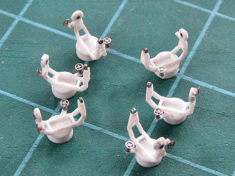
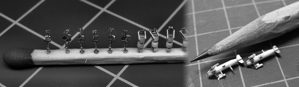
Here’s the completed frame. The base part is made using my new lathe The lower base part has a conical shape and a 2mm gap so that it can be fitted easily on a disk on the model. The top part of the base is a small disk but with a very small 2mm extension so that it fits concentrically in the lower base part.
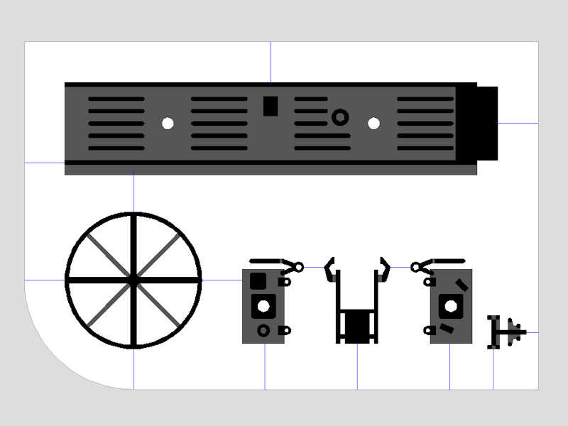
This is the design for the lantern which will be nearly all photoetch except for a small disk to close the part off. I couldn’t add all the required detail in a double-layer part, so I made three additional part to be glued onto the main part. The two parts for the side will be aligned using some rod, the top part will be aligned using the small square visible in the middle of the main part. Should be a nice folding exercise!
Go on to part II.