After having bought the drill press, I bought a small lathe by Proxxon. I owned an older Emco Compact 8 for a while but only used it on occasion as it needed more space to operate than I had. I lost a few parts moving it to my new house and the live center was completely stuck in the tail stock. I damaged the lathe while trying to repair it (how typical) and decided I wanted a smaller, newer, and more compact lathe. Easy access to spare parts is a diminishing feature of the Elco, let alone access to affordable spare parts. Similar to their drill presses, Proxxon offers two lathes, the PD230/E (small) and the PD400 (large), but the differences between them are large enough to look more closely before deciding. The PD400 has twice the distance between the centers, weighs 45 kg, and has a spindle bore of 20.5 mm while the PD230 weights only 10 kg, but has a smaller spindle bore of 10.5 mm. This meets my needs perfectly for a small tool that I can easily store in my hobby room. The PD230 has the same range as accessories as the PD400—including milling and drilling equipment—(except a quick-change holder for a parting tool and the traversing steady). A disadvantage of the Proxxon lathes is that they each come with their own chucks, clamps and collets, and share few parts among them including the mill/drill upgrade. This shouldn’t be a problem as I do not want to have two lathes now, but the PD400 can also be bought as a CNC version. It is too expensive for me now (listed at €4400. The other list prices are €930 for the smaller and €2300 for the larger lathe) but might be a nice option in the future requiring me to possibly buy all these items once more. The lower cost, weight, and footprint of the PD230 made it the logical choice for now. I purchased the lathe on Ebay for €699 from a German reseller with an Ebay-nick of Briggebaecker.
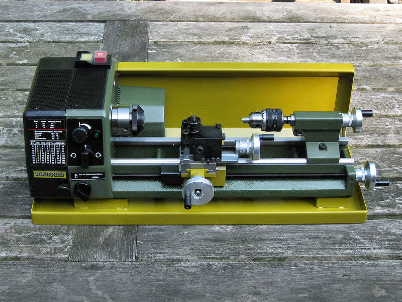
Here’s the lathe including the “Splash guard and chip collecting tray” (24006). I decided to have a few accessories with the lathe. This first one is a collet set (24042) for better accuracy (centricity) and easy of use . As I intend to use styrene when possible, I want to minimize damage of the styrene of the three-way chuck leading to the part being off-center, but this is a very expensive accessory. However, it will be very easy to use with stock styrene and brass rod and the collets come in a range of 2.0, 2.5, 3.0, 4.0, 5.0, 6.0, 8.0, and 10.0 mm. (postscript July 2010: I never use the collet set. The three-jay chuck is just fine) The second accessory is a gear chuck (24020) for drilling. I expect this will really be an improvement over using tubing with a given inner diameter. Of course, without the cutters the lathe won’t work so I also threw in a set of cutters (24530). The last accessory is a quick-change holder for the easy change of cutters (24022). I’m not too sure I’ll be using it often but I’ve seen machinists use them and they looked very convenient as you do not need thin metal sheet to change the height of the tool. This part is fitted on the PD400 by default, but is again a different type and parts are not interchangeable. (postscript July 2010: the quick-change holder is a necessity, not an option!). The PD230 also doesn’t have the parting-tool holder and cutter for its quick-change holder according to the brochure of Proxxon. The last item is a center turning attachment (24070) which might be nice for longer parts.
The lathe comes with a a change gear set for wire cutting (left and right handed), live center (MT-1), three-way chuck and a set of hex keys, so no need to worry about different types of screws here. The PD230 can be used for thread cutting although I do not foresee I will be using that option. The lead screw, cross and top slide, tail stock, and tail stock sleeve position can all be fixed, though not too tight. The tail stock sleeve is fixed by a bolt and not by a hex screw. All the functions my old Emco had are present, although the Proxxon has less screws to properly calibrate all positions.
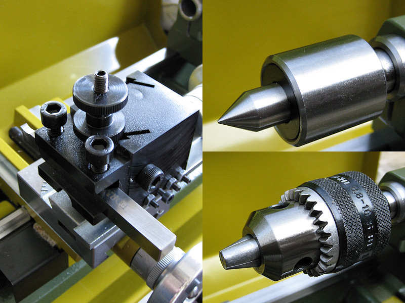
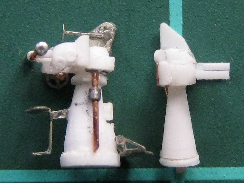
The quick-change holder is seen at left, the live center (included) and gear chuck at right.
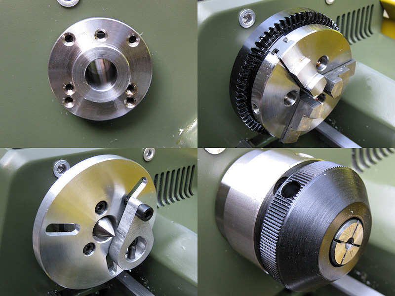
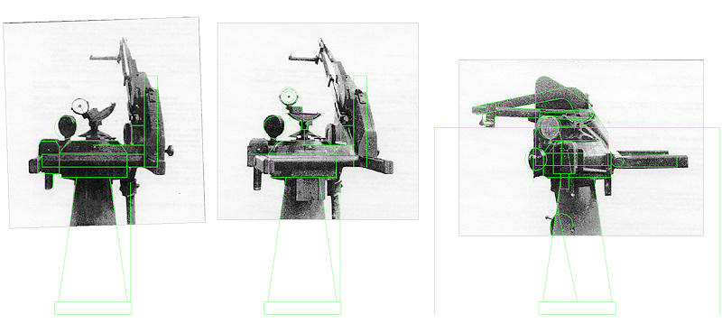
Several items can be attached to the lathe. The top left picture shows both a triple and quadruple array of bolts to fix chucks to the headstock. The three-jaw chuck is shown at right. Proxxon does sell a four-way chuck (24030) but I don’t think I’ll even need it. The bottom-left image shows the center turning attachment. The free-hanging bit on the right is clamped on the work piece which is on its turn mounted on the center. The screw fits in the slot and will rotate the workpiece. Apparently more accurate to use, but also very nice to fix certain parts between the centers. At right the collet chuck is shown. The collet chuck of the Elco automatically pulls out the collet when the chuck is loosened, but not so for the Proxxon. You need to hit it with some stock rod through the spindle bore if the collet won’t come out easily.
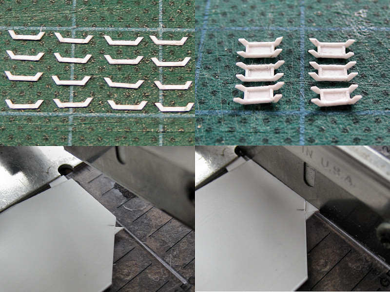
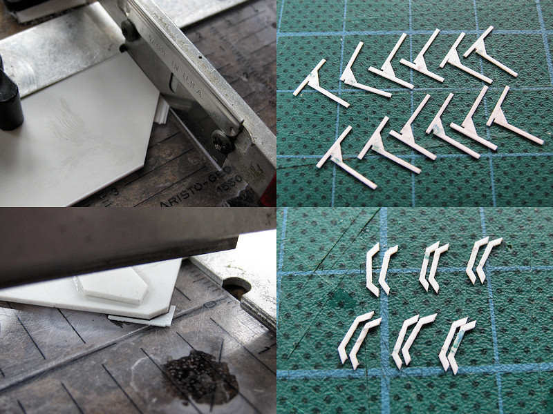
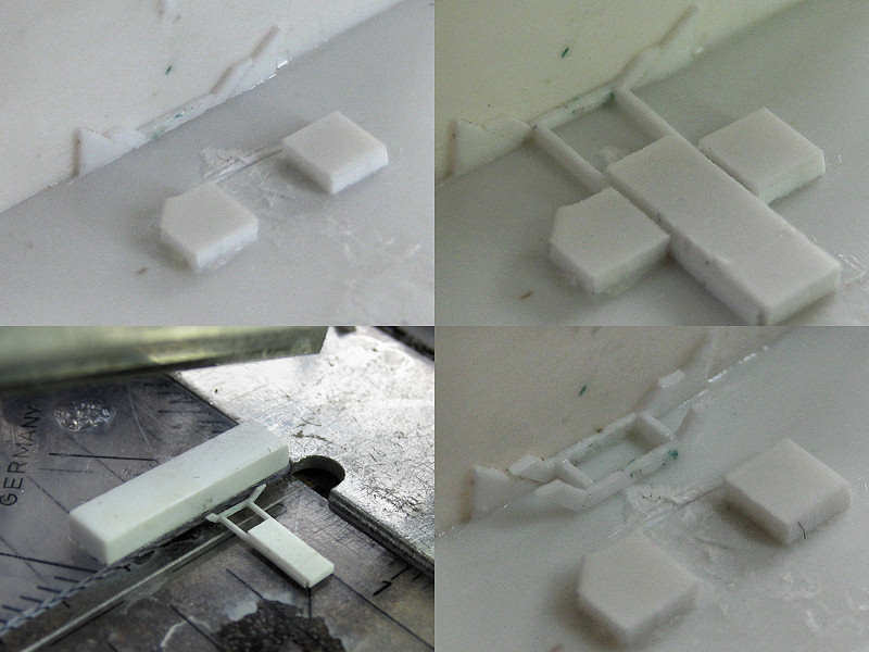
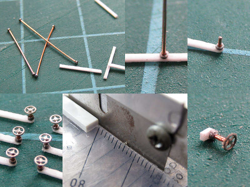
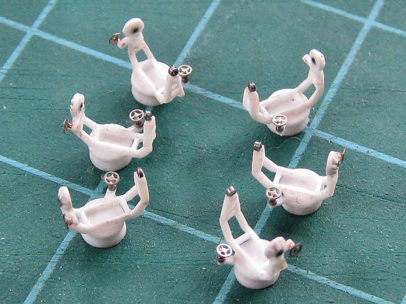
I first spent a few hours taking the lathe apart, cleaning up the grease, oiling it, and putting it back together again. I started experimenting with 4.0 mm styrene rod. You have to be careful choosing a low rpm for the parting and drilling, as they quickly melt the styrene. The parting tool by Proxxon is just over 3 mm wide, which is a bit too much for the poor 4 mm rod to handle. I intend to make a very thin parting tool and have Micromark’s cut-off tool holder on order (82753), a small tool that holds a thin cut-off blade. I intend to grind one cut-off blade to a much tinner width and see if that works. Micromark sells many additional extras for the American variant of the Proxxon, called the Microlux minilathe. There are many more accessories for the Microlux than the Proxxon, even a digital readout.