As a full scratch build, having a custom photoetch (PE) set isn’t that far fetched. When I started drawing the set, Trumpeter hadn’t released its model and the only available sets were those of Iron Shipwright’s and White Ensign Model’s. Neither set was any good at all. Now several sets are available with the only interesting sets those of White Ensign Models (new set), Lion Roar.
I specifically do not include Gold Medal Models (GMM). Although I have used GMM sets with great enthusiasm in the past (sniff, memories), their sets are still according to the trusted GMM design: a (for current standards) small set with railings (50% of the set), generic parts for some navy (40% of the set) plus a few dedicated parts for the ship in question (10%). I feel this setup is outdated considering the huge PE-sets other manufacturers produce and their new sets sell you the same parts in a reshuffled configuration. The added HMS Hood detail set is “nice”, but not spectacular. The etching quality has always been very good though.
The Lion Roar set is quite impressive when you see all the frets lined up, but on closer inspection the etching design is crude and contains many errors. I feel it is, well, clunky. I think Lion Roar has a long way to go in designing their PE. With the release of the Japanese aircraft carrier flight deck sets, I do think they are improving and have released a truly innovative replacement part. They also released a very nifty HMS Hood main turret in resin which is clearly made superbly, but they managed to completely botch up the rangefinder and the barrel is crap. In short, it’s a great set for a beginner who’s not afraid to spend half their building time knee-deep in superglue, but not really useful for a more demanding HMS Hood modeler.
I like the White Ensign Model set best, having the most HMS Hood specific parts and add to that the most correct Royal Navy parts. This might have something to do with the fact I sent them my etch set and I recognize a few parts, although they’ll deny it, of course. But, having already admitted to designing my own etch set, the WEM set was a bit late for me to use. Plus, even White Ensign Models didn’t nearly include all the parts I wanted for my own model.
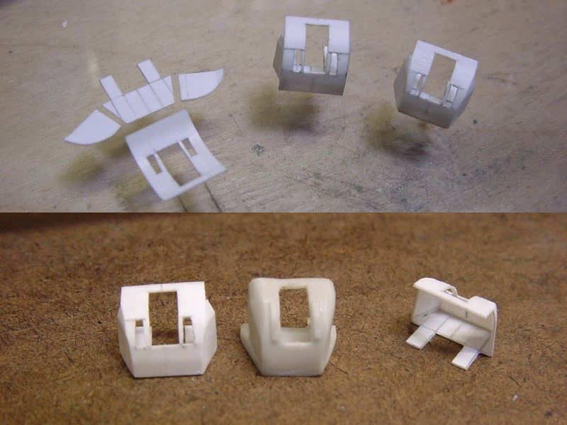
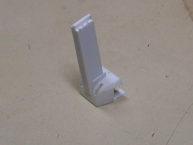
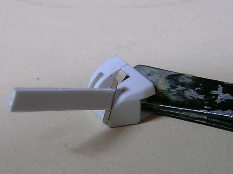
So, custom-design PE sounds like the ideal solution, but it didn’t quite turn out that way. I spent far too much time tinkering with the drawings and adding more detail loosing sight of the final size of the part. All the stairs, each of them designed to fit the exact deck height and width for their specific location, all snapped in half when I tried to bend them. The material isn’t very malleable and some folding lines weren’t etched properly (designed too thin). So, the set is definitely to be etched in a new form hopefully without beginner errors. But on the other hand, some parts turned out fantastically!
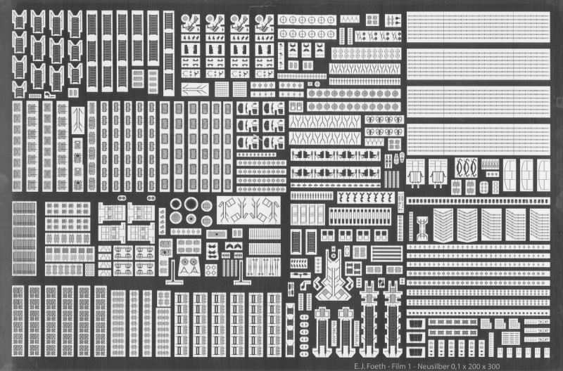
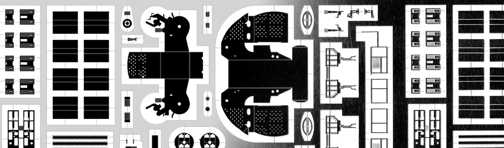
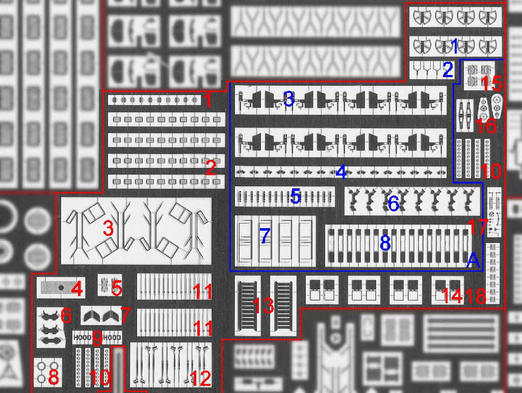
So, this is the entire set. I didn’t do the printing and etching myself, this was done by Saemann-aetztechnik in Germany.
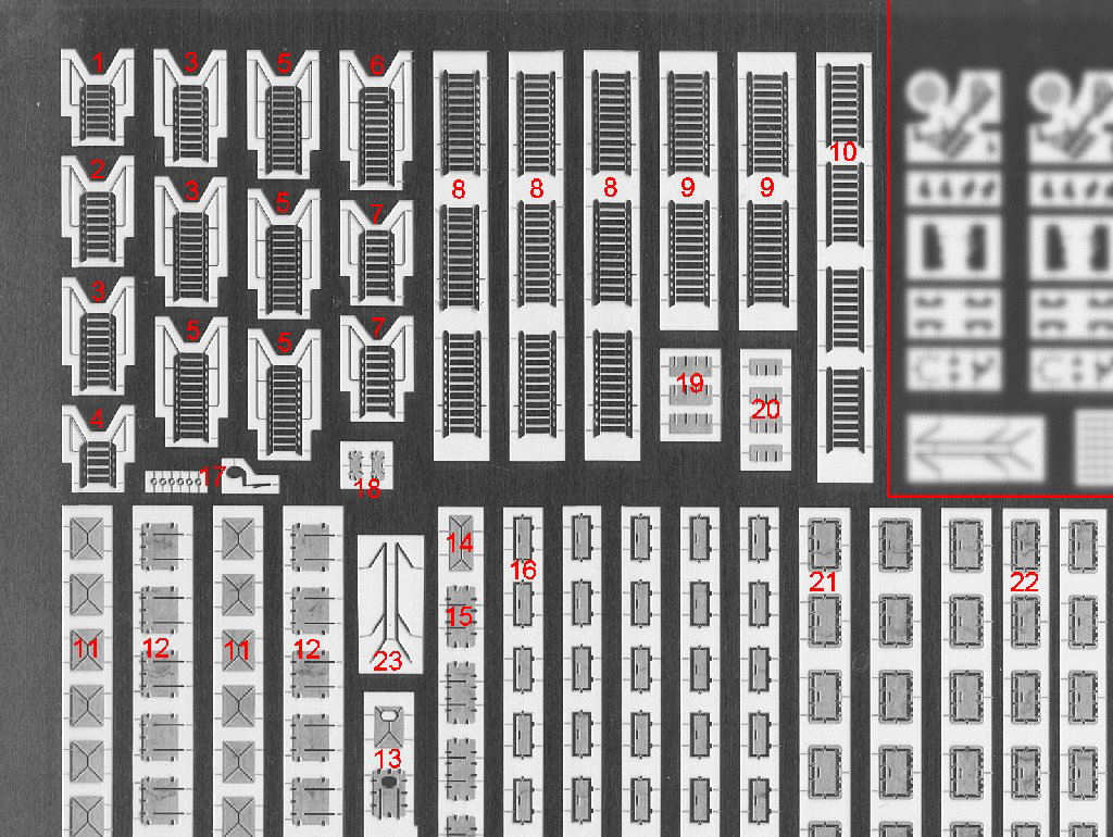
1-10 Assorted stairs
11-12 Deck hatches including inside detail plate
13 Quartedeck deck hatch
14-15 Ammo loading hatches plus inside detail playe
16 Superstructure doors
17 30ft gig detail
18 Quad Vickers ammo locker hatches
19-20 Boiler room uptake vent hatches
21-22 Assorted watertight doors, correct style
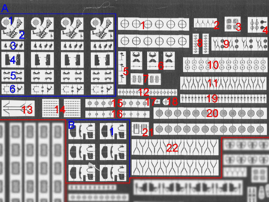
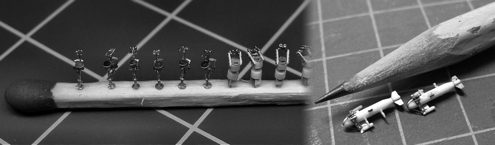
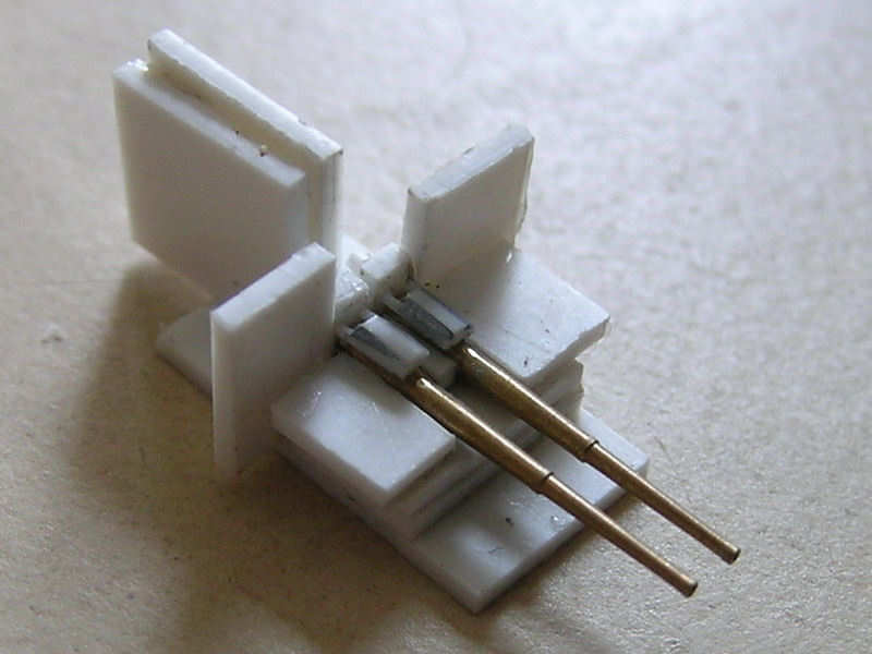
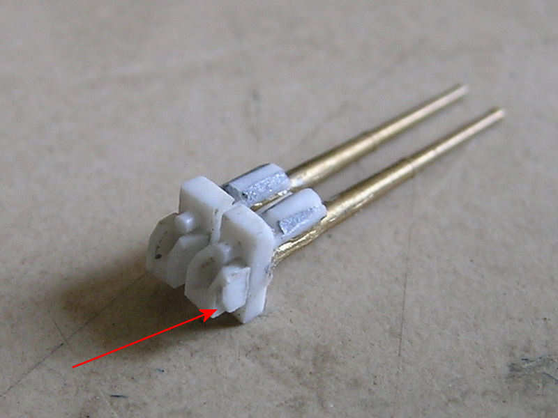
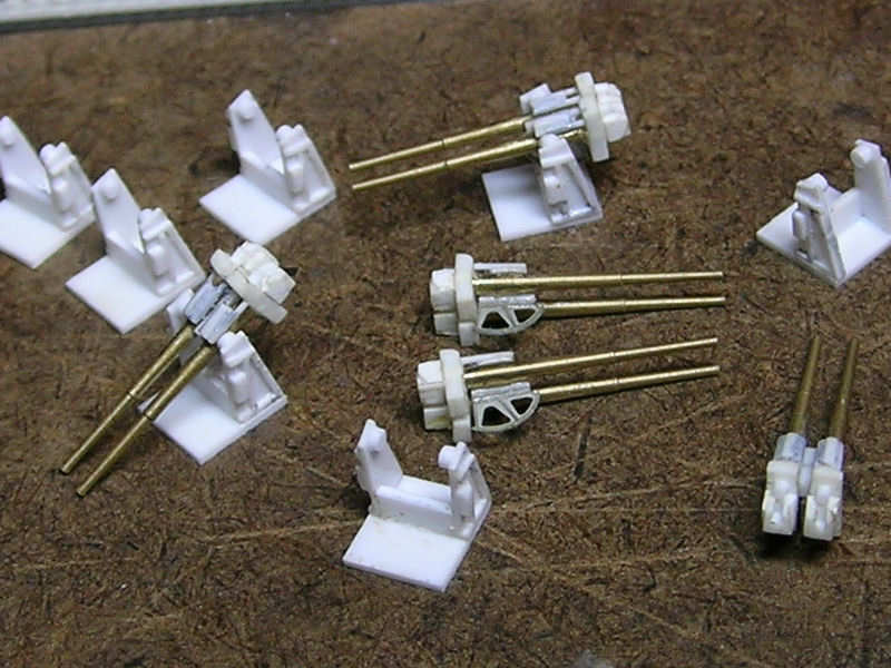
A Quad Vickers detail parts
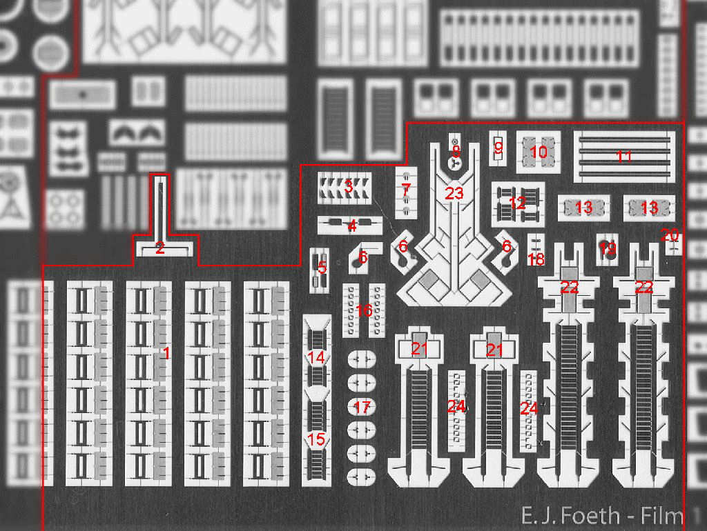
1 base plate
2 Frame
3 Spent casing bins
4 Shields
5 Ammo drums
6 Assorted detail
B Paravane, assorted detail
1 Searchlight covers
2 twin 4″ ammo loading lights
3 Quarterdeck bulkhead hatch, inner
4 Crane pulley
5 Pompom director seats
6 Pompom director, assorted detail
7 Quad Vickers ammo locker hatches
8 32ft cutter detail (unusable)
9 Small reels
10-12 Medium reels
20+22 Large reels
21 Quarterdeck bulkhead vent hatch
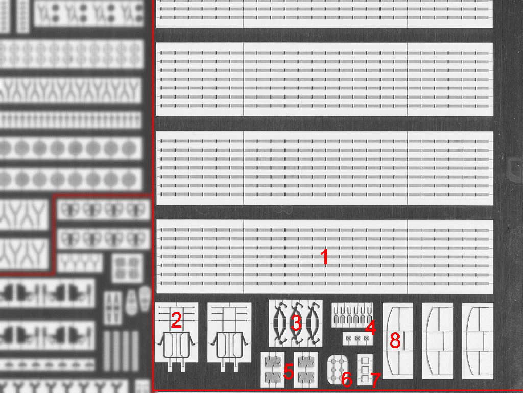
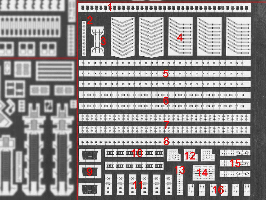
1 Degaussing cable (not used)
2 Night lifebuoy rack
3 HACS inside detail
4 HACS, assorted detail (over scale)
5 Pompom ammo locker hatches
6 Funnel grid detail
7 HACS detail
8 Deck hatch awning support
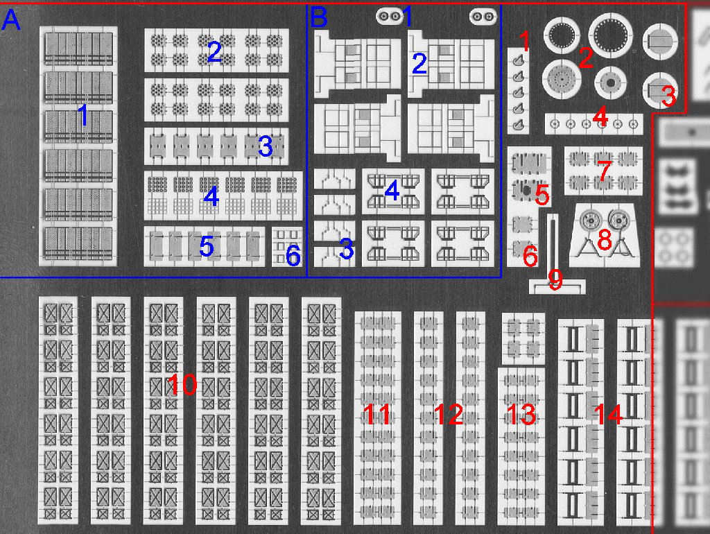
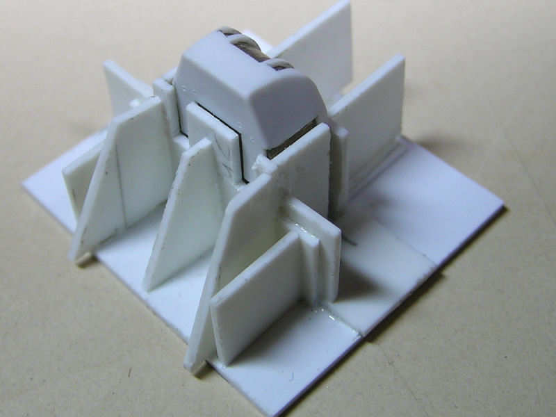
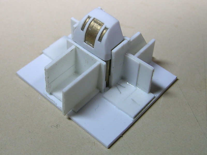
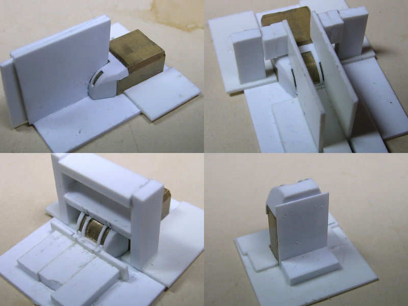
A UP launcher
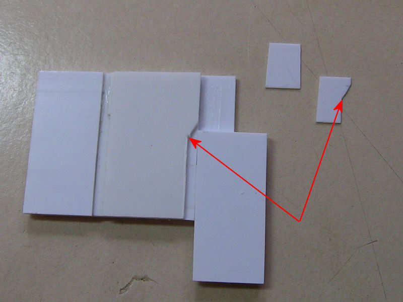
1 Casing
2 Ammo locker hatches
3 hatch
4 Front/rear casing detail
5 Door
6 Window frame
B Pompom
1 Traversing engine detail
2 Railing
3 Hand wheels
4 Ammo locker frame
1 Commanders hatch main turret
2 Capstan, assorted detail
3 hatch for boat deck
4 Assorted detail
5 Torpedo loading hatch (can you spot the error?)
6 Pompom ammo locker hatches
7 Ammo hoist hatches for the boat deck
8 Large reel
9 Spotting top detail
10 twin 4″ ammo locker hatches
11-13 Single, double, and quadruple skylight hatches
14 Deck locker detail
4″ gun
1 Elevation gear
2 Loading lights
3 handwheels and assorted detail
4&5 Fuze setting device detail
6 Traversing gearbox
7 Awning support
8 Vision port hatches
1 Signal light detail
2 Mushroom vent detail
3 Admiralty ladder handrails
4 Quarterdeck detail
5 Pompom ammo locker hatches
6 Main crane pulleys
7 Clump cat heads
8 Main derrick detail (not used)
9 Ships name
10 Eyelets
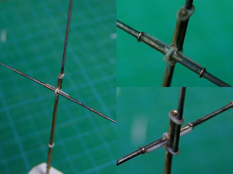
11 Rigging details
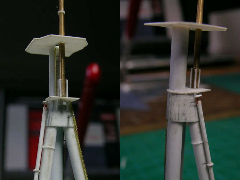
12 Mast stay detail
13 Assorted stairs
14 Quarterdeck bulkhead hatch
15 Quarterdeck bulkhead hatch, inner
16 Sounding machine
17 Skimming dish, assorted detail
18 Assorted deck hatches
1 Deck locker detail
2 Spotting top detail
3 45ft barge detail
4 45ft barge rudders
5 Rangefinder hatches
6 Boat rudders
7 Assorted deck hatches
8 45ft barge steering wheel and propeller
9 45ft barge railing
10 Voice pipe cabinet hatches
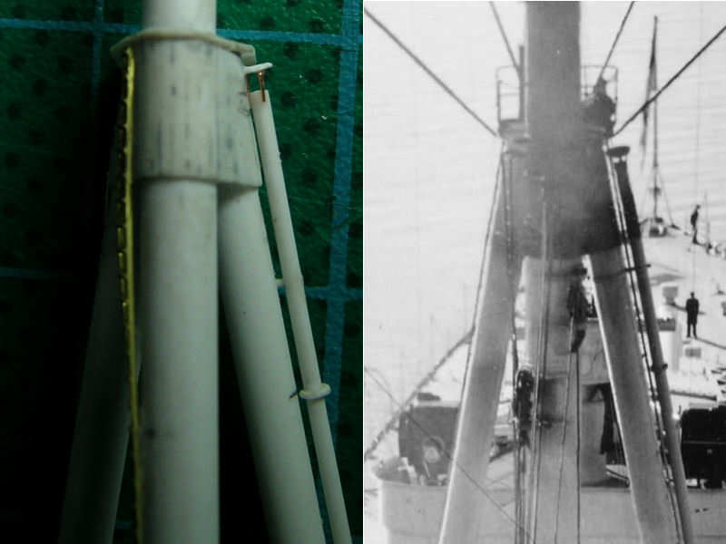
11 Mast detail
12 Assorted stairs
13 Paravane locker hatches
14 Assorted stairs
15 Assorted stairs
16 Cutter details (not used)
17 Fast motor boat propellers
18 Boat rudder details
19 Boat rudders
20 Boat rudder details
21 Boarding ladders, short
22 Boarding ladders, long
23 Boarding ladder handrails
24 Boat detail
1 Assorted seats
2 Random detail
3 Frame for bridge
4 Degaussing cable (not used)
5&6 Mushroom vent detail
7 Assorted hand wheels (4 and 5 spoke)
8 Assorted seats
9 35ft fast motor boat engine hatches
10 35ft fast motor boat stairs
11 Fast motor boat, assorted detail
12 35ft fast motor boat, handrails
13 Too small
14 Assorted handrails
15 25ft fast motor boat, windshields and too small parts
16 Fast motor boats, propeller shafts