Category: Deck

Shelterdeck, part I

Hood modellers were recently confronted with two changes in HMS Hood’s appearance. The first one related to the underwater hull; it was most likely never red, but either slate or black. Research is ongoing and I expect the painting guide of HMS Hood on the official website to be updated soon. Second, we had a discussion on the application of Corticine on board HMS Hood (Corticine is often spelled Corticene in admiralty records). Corticine is a linoleum-like substance, a ground cork and caoutchouc or India rubber mixture, that was added to the decks as an anti-slip measure. On the exterior it was usually applied for bridge deck areas where the crew was expected to stand for prolonged durations. Dave Weldon, who studied HMS Hood a fair bit longer than I did, has Corticine on the shelterdeck of his Hood model the large open area around the bridge and funnels. I had noticed that this area had a rectangular gridded pattern on the deck, but never made the connection this could be corticine. After all, these lines follow the plate pattern of the deck and no appreciable contrast change with the rest of the ship is observed.  But the gridded pattern is a strip pattern, and upon closer inspection of photographs and based the logs corticine, as well as an a lengthy discussion with the Hood Association, we came to the conclusion that corticine was indeed present. The pattern is estimated to have a 6ft x 12ft spacing, laid symmetrically with regard tot he ship centreline and starting on the expansion joint that runs through the emplacement of the forward pompoms.

The ship logs also indicate that Semtex was added in 1937. Semtex is also an anti-slip material, trowelled on and confined at the edges by small headings of steel welding on deck. It was a rough material said to wear down shoes quickly.  It can appear in several colours, reported to be light grey, tan, blue, green, or red brown, with only tan and light gray as an early WWII option, depending on the manufacturer (They remain unspecified in the logs of HMS Hood). The location of the Semtex is indicated near the emplacements of the 4inch high-angle guns. When we look a bit closer on all the images of the deck it is clear that the grid pattern is only partially present, indicative of both Semtex and Corticine regions; many of these pictures were taken in either 1940 or 1941. So, with some certainly we can now say that the entire shelter deck is either wood, Corticine, or Semtex; there is no spot of dark deck grey to be seen (not counting on top of the various deck structures).

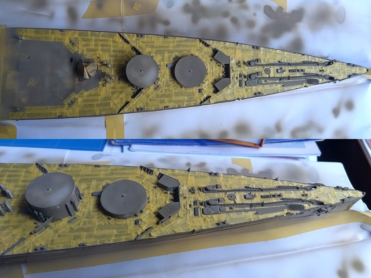
With this new information I went to work, adding the lines in stretched sprue; this material is cheap to make, and can be easily glued with the sprue pulled taut on the deck. The difficult is aligning all these lines with so many obstructions already on the deck, so I had to mark all positions carefully and use tape to fixed the lines fore adding glue. Calipers were often used to get the distances correct. Some lines were not entirely satisfactory and were replaced. The far foredeck was especially tricky but worked out very well. The the pompom area was given a corticine treatment as well, but that was later shown to be incorrect.

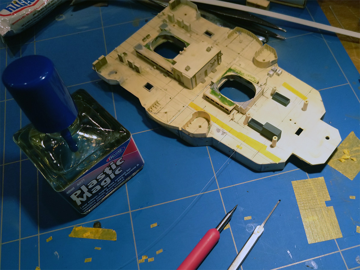
I recently picked up a bottle of Plastic Magic via a tip on the Britmodeler forum; it’s a very thin liquid cement that you can apply by a fine brush, similar to Tamiya’s Extra thin cement. I always used Uhu’s (with the needle dispenser) or sometimes glued using thinners. This new glue is much easier to use, and I wonder why I didn’t pick up these thin glues earlier. This is a small experiment with a 0.13×0.20mm strip that could be glued very easily. Note that there are three ammo lockers forward of the UP launch emplacements; these are on many drawings but not on any photograph and were removed, causing a lot of damage to the deck,

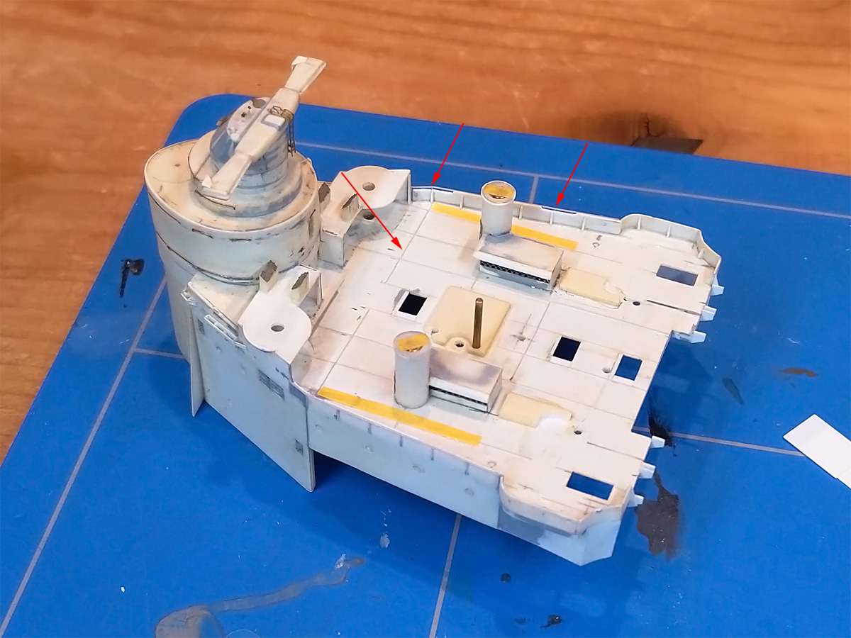
The bridge deck was also covered with styrene, so here’s a shot of the strips in process; this part isn’t done yet. While I was at it, I carved out a small step in the splinter shielding where the saluting guns used to be present.

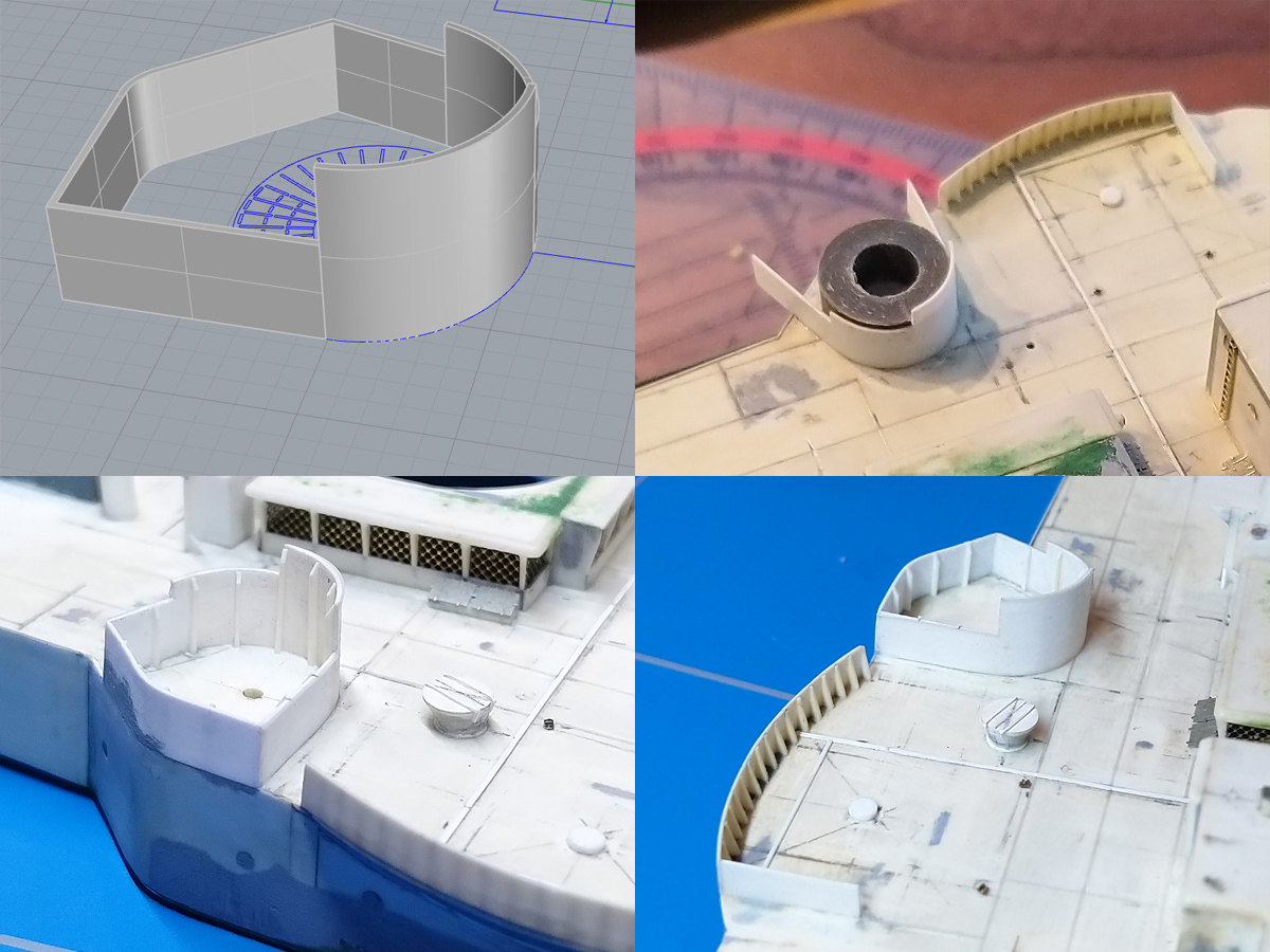
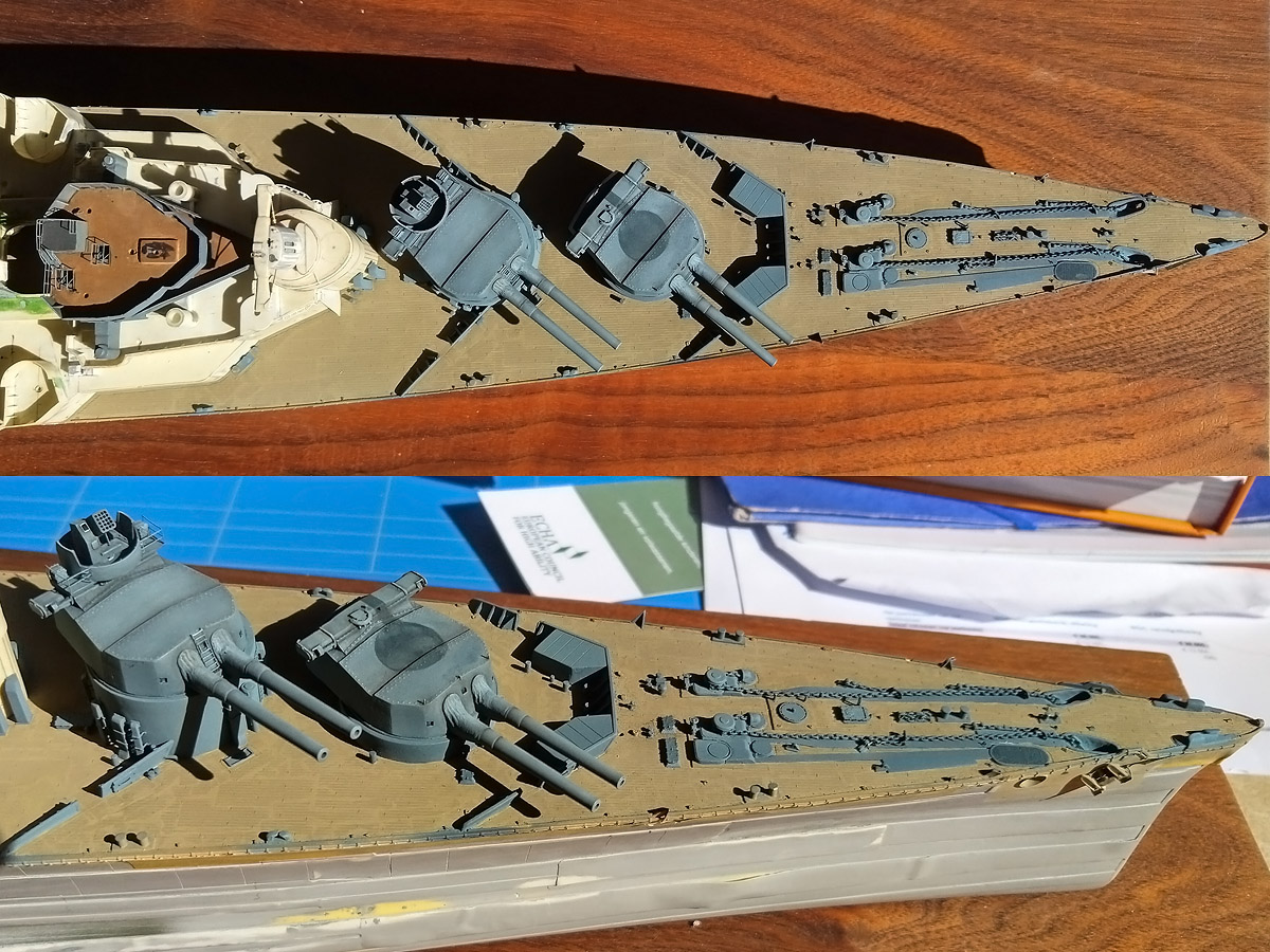
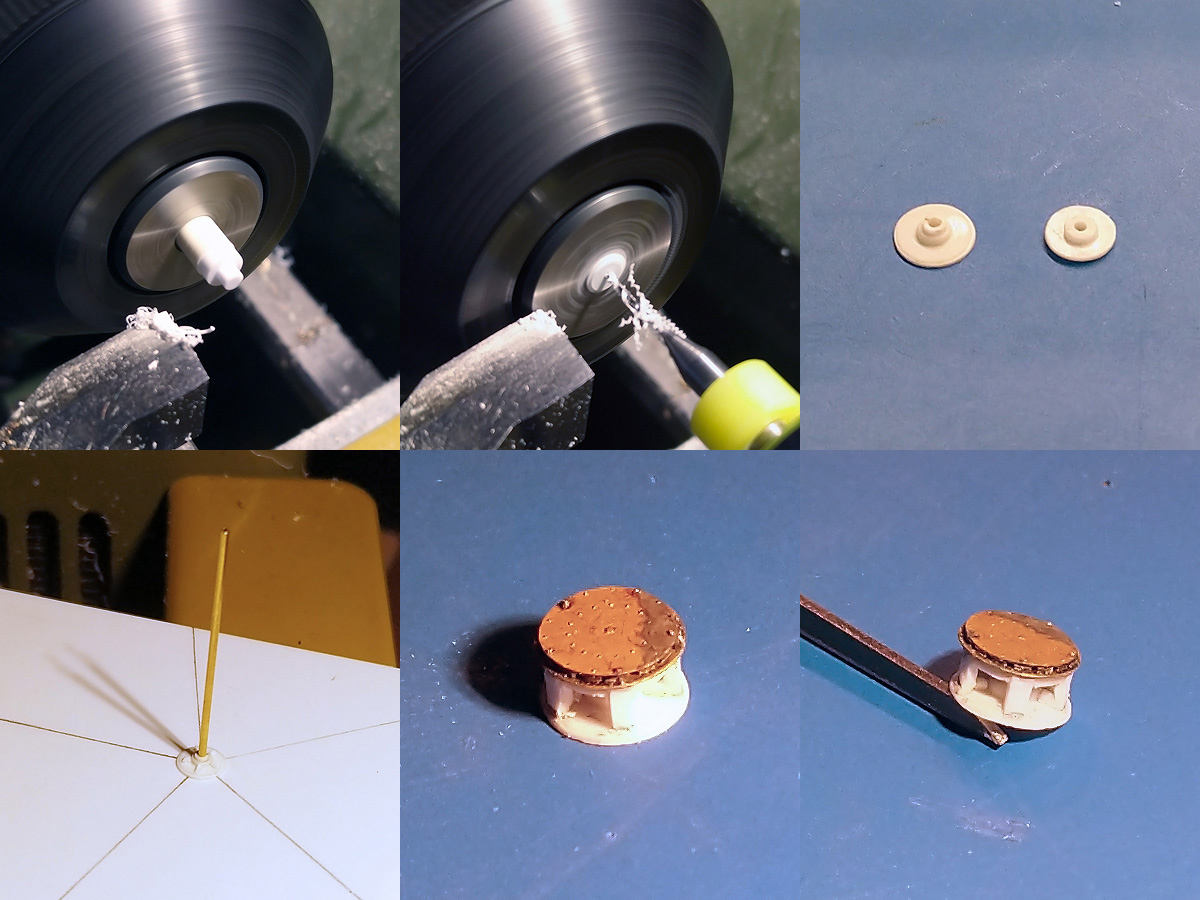
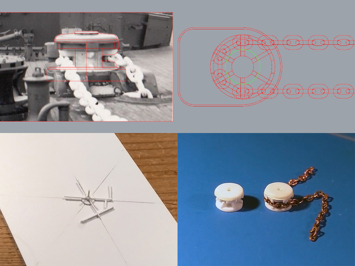
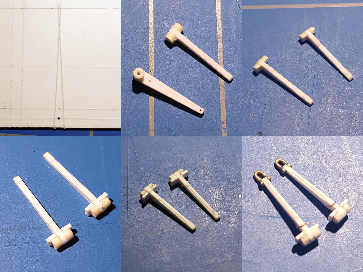
While adding the strips I noticed that all the parts on the model aligned with the 12x6ft corticine strip pattern except the forward UP splinter shielding. Plus a new pic showed I didn’t have the outline exactly right. I made a small model in Rhino first. I made a small plug on the lathe to help positioning the shield during gluing. Small stiffeners were added, as well as a small aerial trunk built from discs and Magic Sculp.

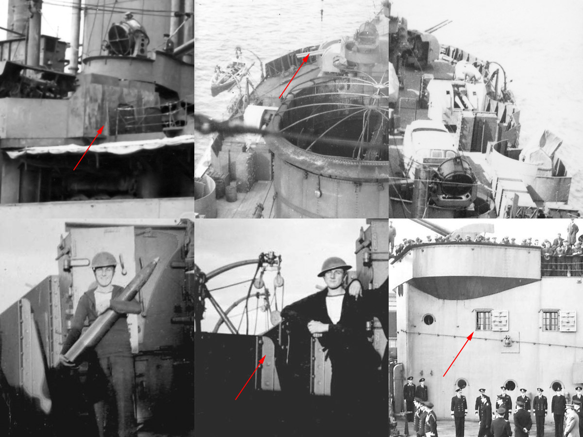
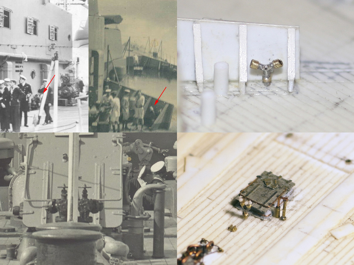
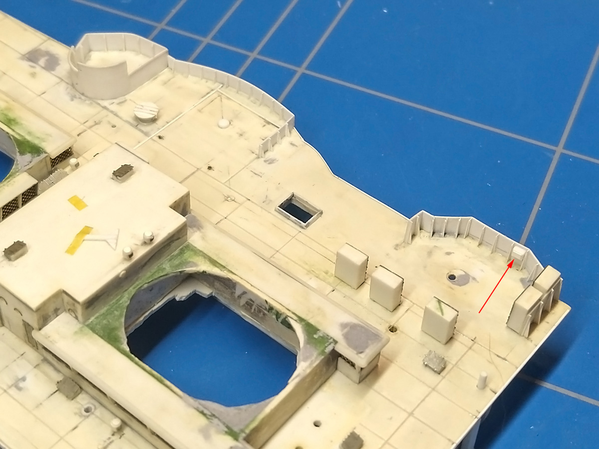
The rest of the splinter shields were only partially finished, many missing the stiffeners in the back. The two pics on the lower row show these strips are a strip and a small triangular plate. Also noticed a small storage container on the after most shield , presumably to store items required for the 4in guns. The bottom-right image shows the windows to the Admiral’s day cabin (with the dining cabin forward, also with two windows per side) that are shown a bit below.

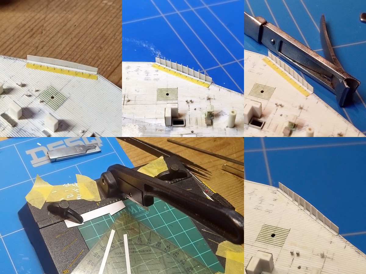
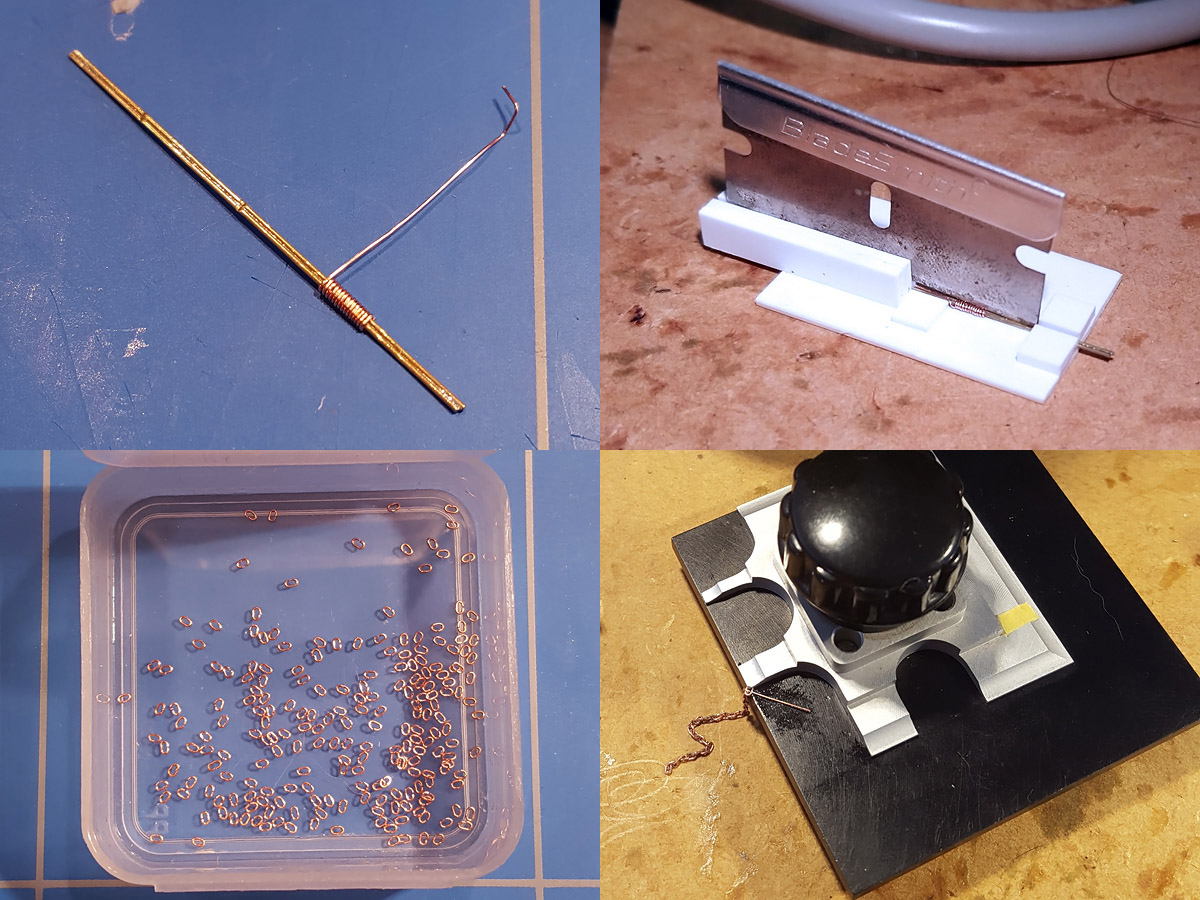
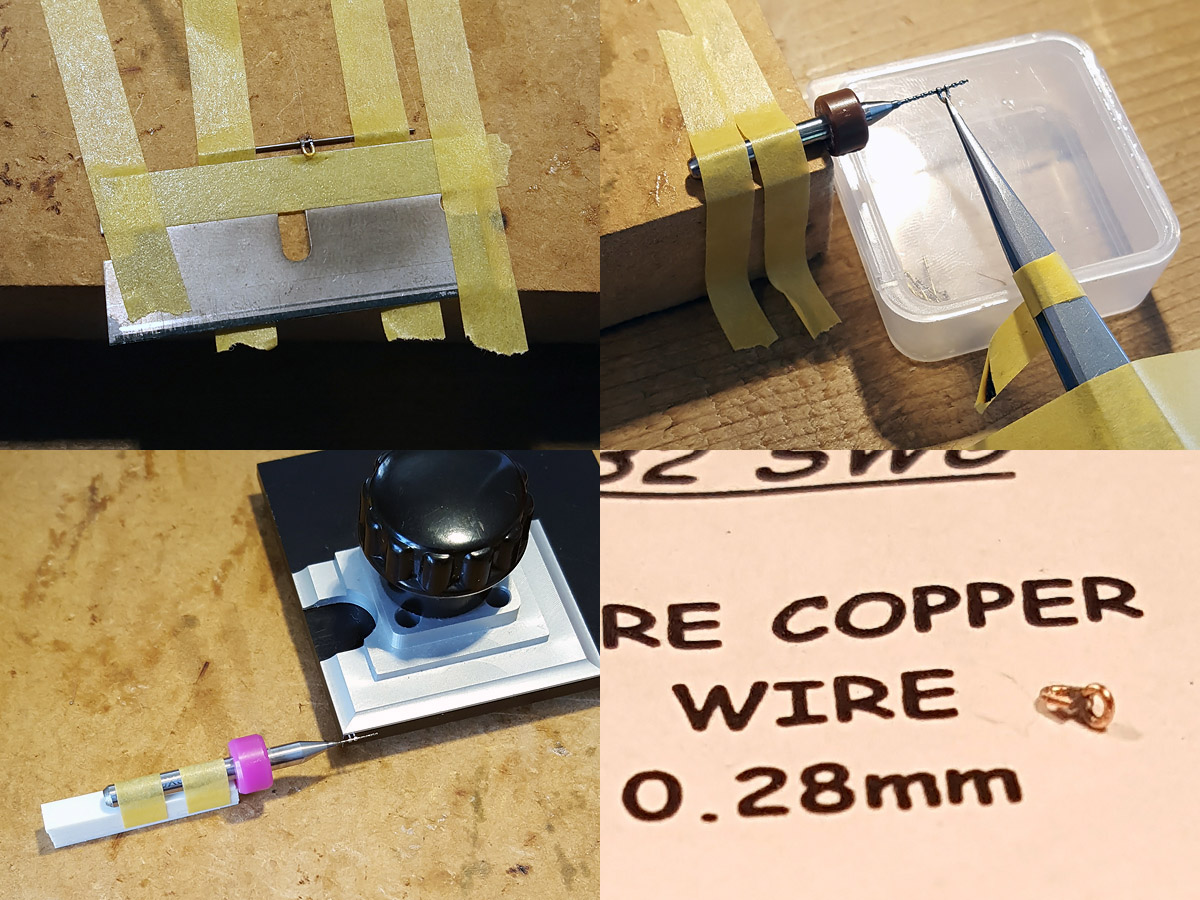
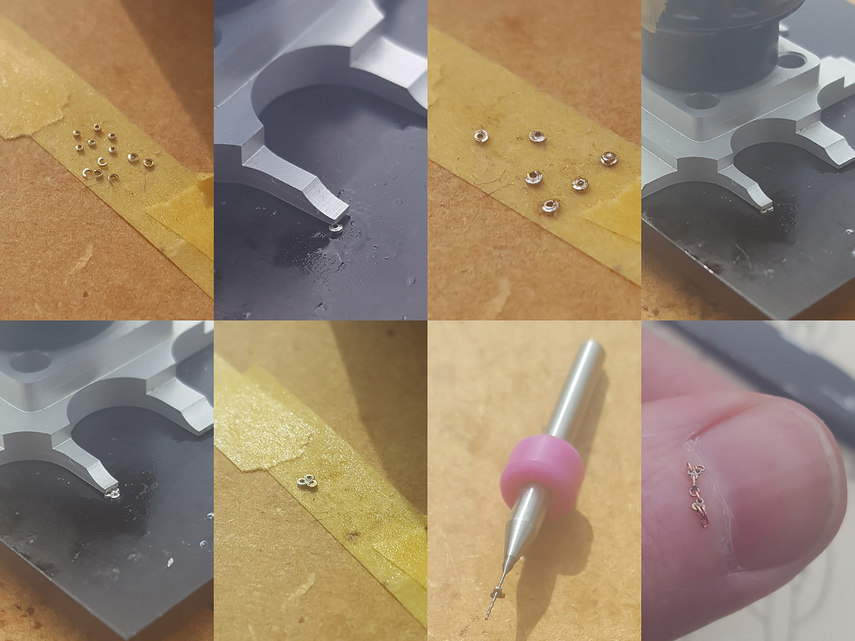
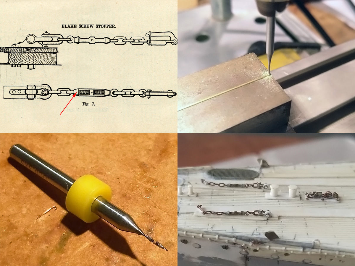
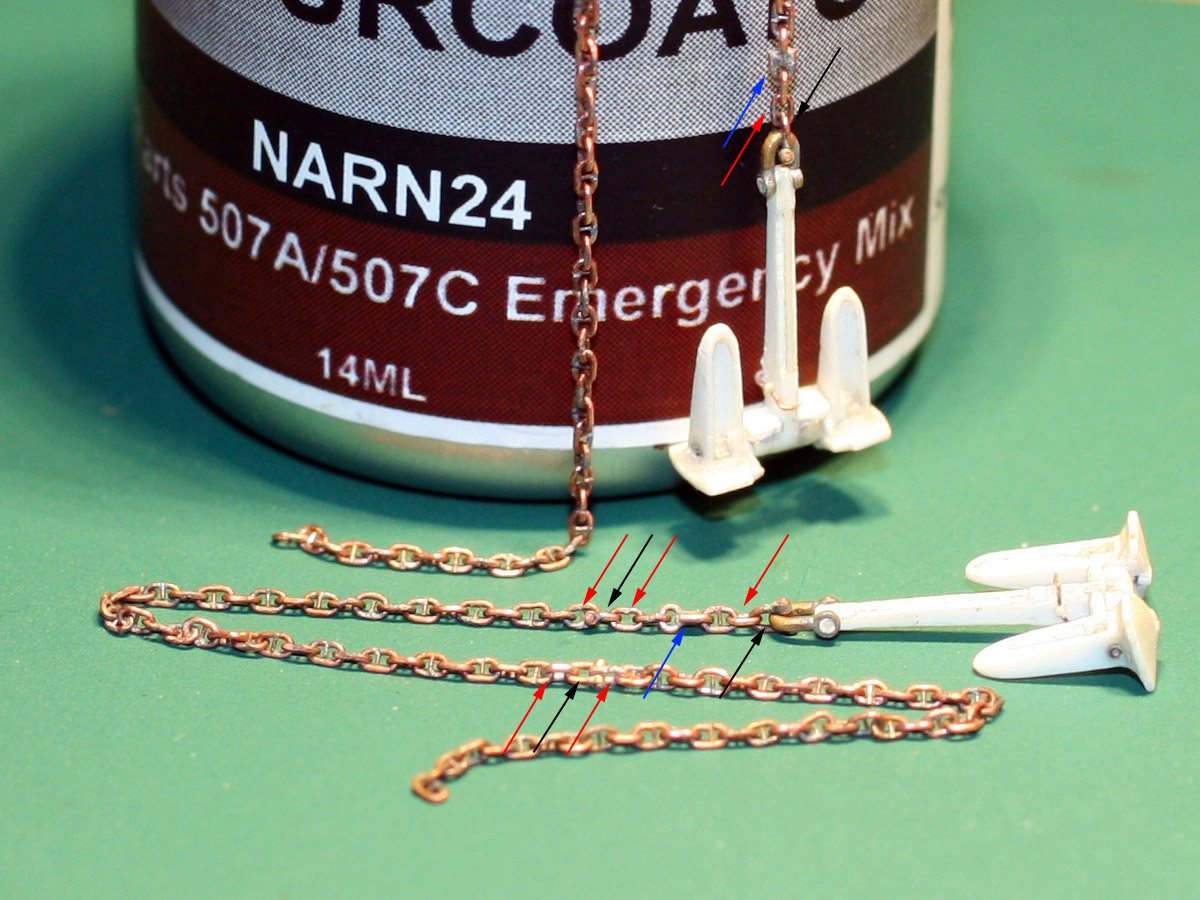
The strips were added by first adding smalls trip of masking tape with the right spacing. Small strips of 0.13mm were added next. When the glue had set these were beheaded using my clipper. A series of support triangles was added next. The photographs show that each triangle is not the same height as the splintershield, so I rounded that the height to the first half foot. The bottom left shows the copper at work, with a series of strips of the correct width. A small styrene template is first used to cut the strip at an angle and then chop it to size.

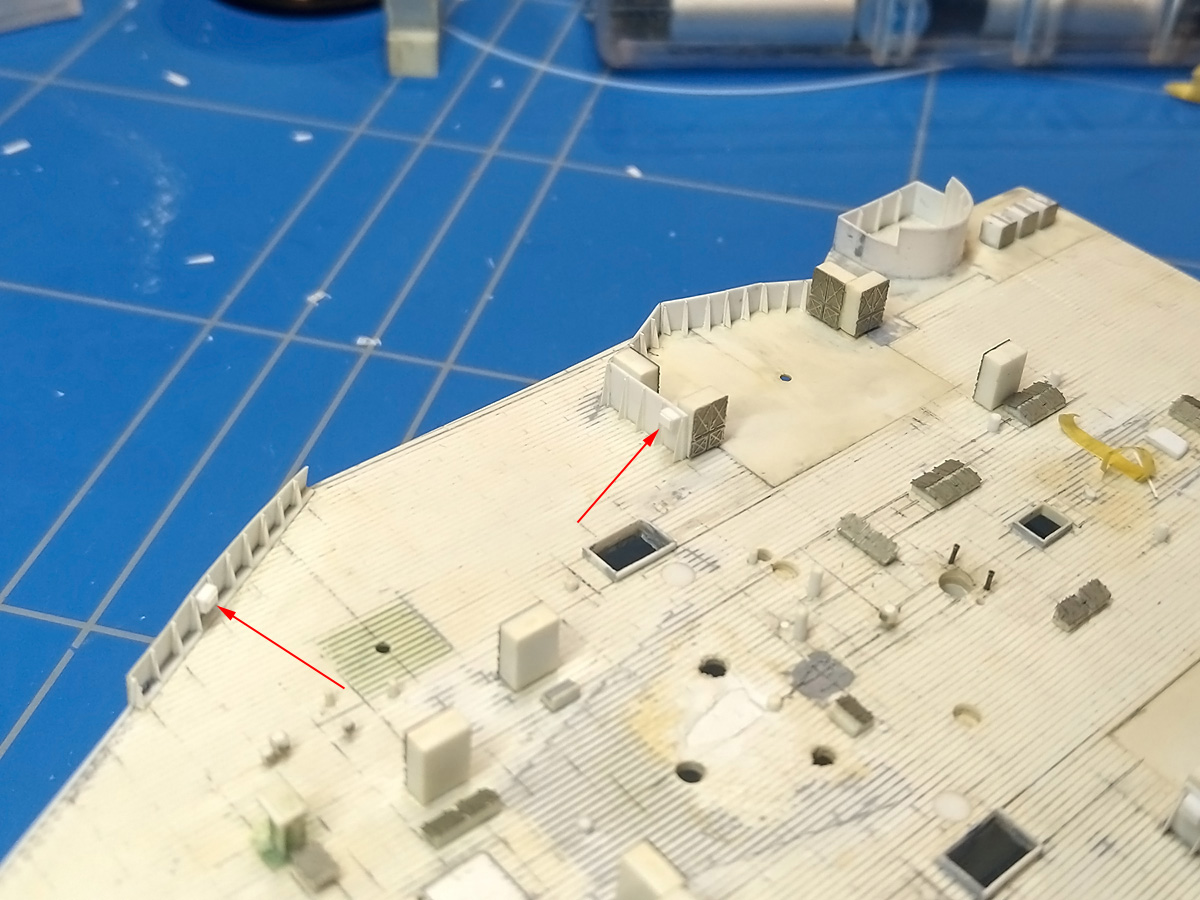
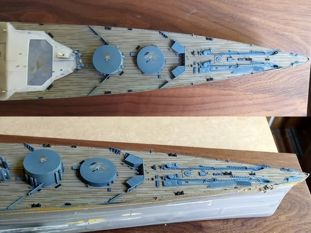
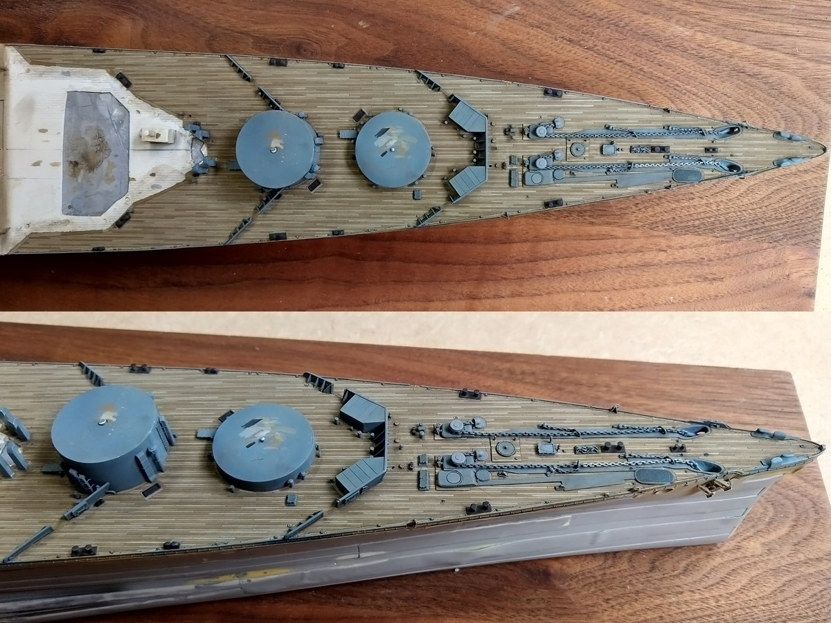
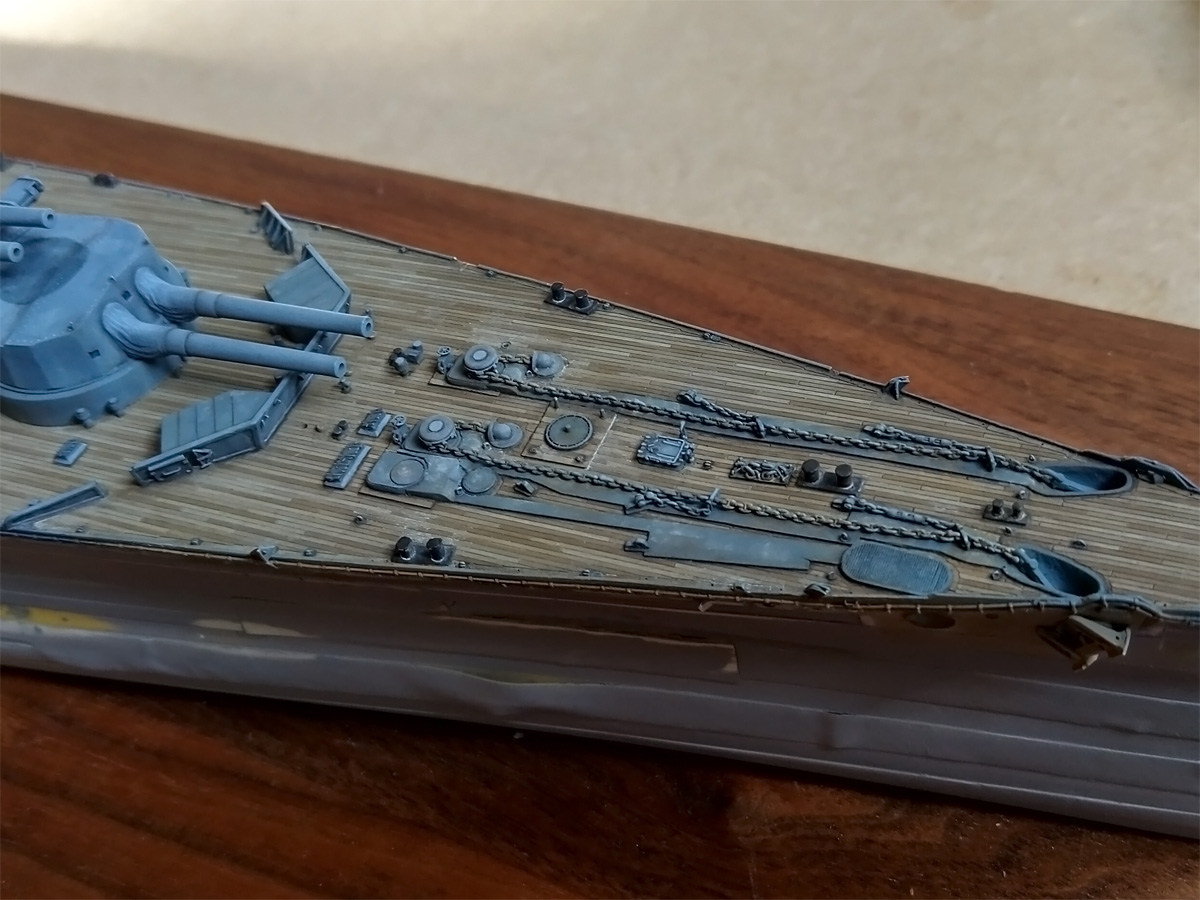
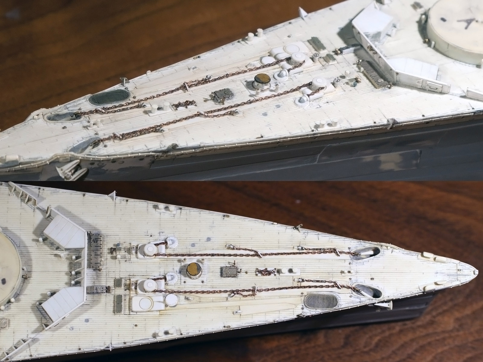
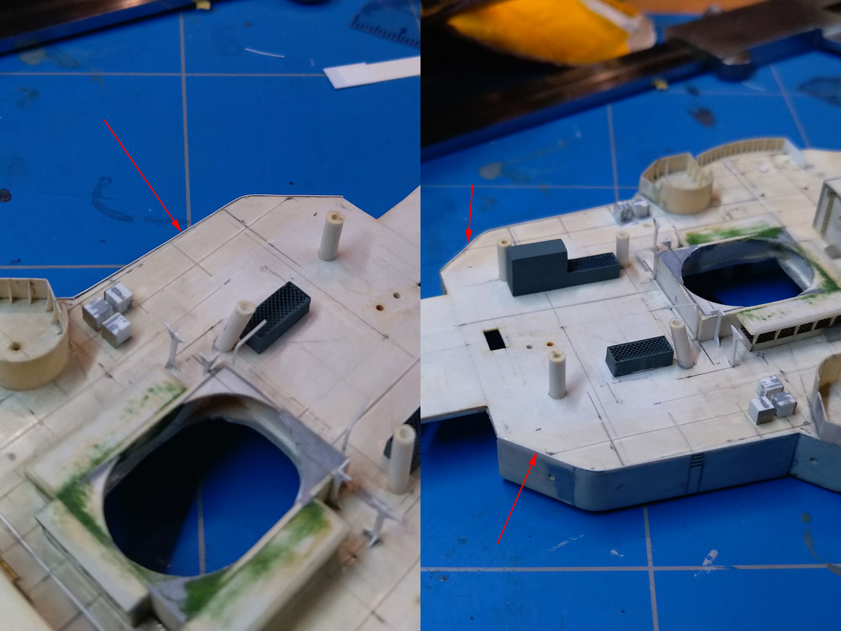
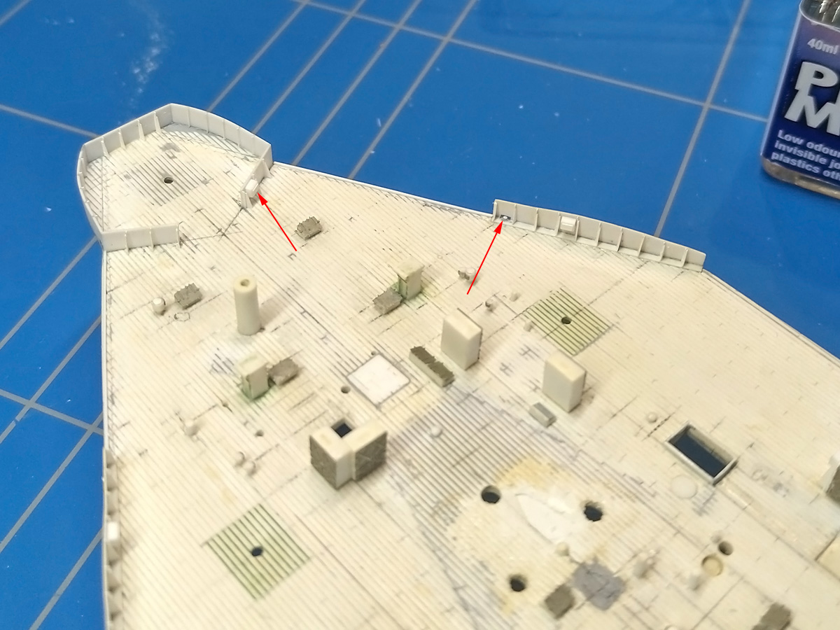
Results of the shelterdeck as it is now; the arrows indicate the location of the lockers, both confirmed in photographs.

The smaller shield as a smaller opening where a small hand wheel was present to lower some shutter. Although I have no good pics of the aft 4in gun emplacement, I added the locker as random detail.

I added another random locker  to the forward 4in gun emplacement, and also replaced the splinter shielding around the pompom in the new style.

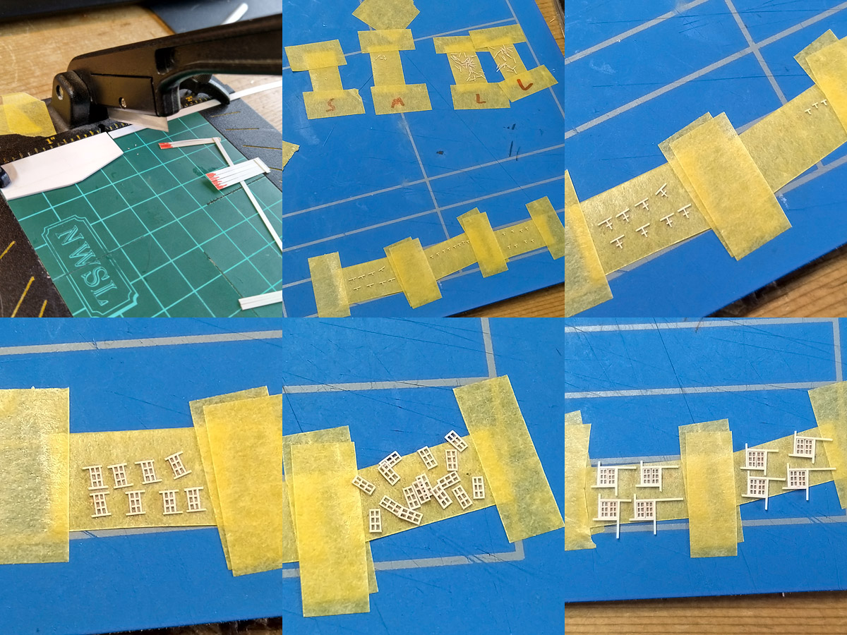
While I was at it I decided to do another experiment with my new glue and built a set of windows for the admiral’s day & dining cabins. The openings are only 2×2 mm, so I needed very thin strips. I used a stop that was touching the blade, giving an about 0.15mm thin strip. This means I’m cutting of slices half the strip thickness. I added a bit of colour to not worry too much which side is “down”. I made a small assembly line using tape; not entirely useless as the small and medium strips were about the same size and initially parts ended up mixed making for bad windows. Building these small parts in series also ensures that the glue can set between each step. A total of 8 windows of 22 parts were built

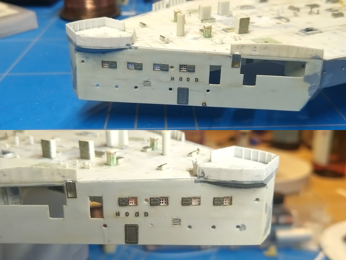
And the result; I had to do some carving to the back plate which was quite unnerving, but nothing went wrong! The rest of the part is in line for cleaning up.

Painting the deck, Part II

A small update of some work that was done earlier and then stalled a bit. The fore deck was next in line for painting. Unfortunately I had a minor disaster with a coat of Humbrol H72 giving rough spots. After brushing the model with alcohol I lightly sanded the deck and removed the grainy surface where I could using pieces of sanding paper glued to toothpicks; etched parts could be scraped clean. Many details are soldered or glued firmly, but the vents around the barbettes are most fragile and took a bit more time. It went well enough, but I was otherwise very much not pleased loosing a day or two that could have been spent painting. Not sure if it insufficient stirring or thinning but it was probably my fault somewhere along the line. Learn by failure I suppose. The result is still not too bad but macro shots will show the bad finish in some areas. Perhaps one of the reasons I dread painting;  some errors are very difficult to correct.

The entire deck was masked after a layer of primer, corrections, and a couple of coats of Humbrol H72, rough-spot corrections and a barrel of Whisky. There’s a lot of detail to work around, so this takes many wee bits of tape. As the deck will be painted by hand it doesn’t have to be too exact.

The rest was sprayed with two coats of my AP507A/B mixture (Humbrol 34  White, 77 Navy Blue and 140 Gull Grey). I initially stored some batches on paint in Badger jars and most of this dried in the jar; I bought a stash of empty tins at https://www.phoenix-paints.co.uk/, including some 125ml tins for storage. Meanwhile, the new Humbrol colours I ordered do not mix to the same colour I had; too blue. With some black and some drops of red the colour might be used as a base. Fortunately I have a a few tins of my old paint  lying around, more that enough to finish the model but if they spoil too more Whisky is in order.  Note that the sandy layer of H72 on the deck shows patterns of masking, as a final insult to my painting troubles, but that didn’t worry me at all.

Then it was a matter of painting in all the plank work again, using the same recipe of Humbrol H72 Khaki Drill, H72+H110 Natural Wood, H72 + white and pure H187 Sand (a discontinued colour). The deck edge details were touched up in the base colour and bollards and steam winch positions in black. The colour of the chains is typically hull colour but one shot from 1940 shots the starboard chain to be a bit lighter, so I copied that to add some variation, in Sovereign Hobby’s AP507C.

Three washes of van Dyk brown followed.  I used Winsor & Newton’s Sansodor as a solvent that dries very slowly, allowing for some touching up and clearing excess wash from the deck with a wet brush (when the wash is starting to set).  The contrast between planks is perhaps too pronounced, but it’s tricky to strike a balance between having contrast differences while at the same time having the deck appear as one colour. The contrast is a bit more than on the quarterdeck with the darkest brown being more brown. Probably the universe telling me to paint as much as possible in a single pass.

The background receives a dot filter first, that is random dots of colour (red, blue, brown, yellow) applied to the base surface spread out by a wet brush. The next stage followed the approach as described by Marijn van Gils in his stellar book “Lexington’s final battle”; the main idea for enhancing contrast not to add a (pin) wash plus a drybrush run, but adding shadows and highlights by a fine brush where needed without affecting the base layer (much). T

he first step in increasing contrast was adding shadow lines using a very fine #000 brush and a black/raw umber mixture plus a #1 brush standing by for corrections. This gives a bit more contrast than a pin wash but also requires more time and control. At first these lines appear to be too dark, but after drying the results become less pronounced, so you really need to try it a few times and overdo it just enough that the results in the end are fine.  It’s particularly well visible at the edges of the deck or top to the capstans. The second step is adding highlights, starting from base colour for correction work where required)a nd adding more H140 Gull Grey the smaller the details get. This really makes all details pop up, especially for the etched details. This phase  was followed by a layer of white spots and smears representing salt deposits of Humbrol Radome Tan; I tried it first on a separate part of the model to see how this would work out and the result is: actually quite good. The light part of the anchor chain was (reversed) drybrushed with the base colour to simulate wear of the light coating; the entire chain received a subtle wash with Humbrol Leather for a combination of rust and sediment. An additional layer with adding darker spots and deposits will follow later. The shadow & highlight stages takes time and some regions are difficult to reach, especially the breakwater where adding these long lines is tricky. Mushrooms and winches were painted separately; hose reels are still on the to-do list. Some minor work will follow to finish this bit but I got distracted be the boat deck…

Ground Tackle, part II

With the cables slowly progressing as discussed in part I a few other bits & pieces were built to fully detail the area in front of the forward breakwater.

The capstan was remade simply because I lost the one I had. These are a nice combination of etched parts and styrene. The main (Napier) capstan is built up from disc and making these discs were tricky to do on a lathe: the parting tool would always deform the styrene. I played with tool angles and revs for a while, but in the end used a different approach by first cutting of a piece of rod with a small step in the diameter (top left). The part would then be reversed and work would continue from the other side with the cutting tool going fully against the chuck (carefully). The top etched parts were a bit of an experiment with three layers of PE and the small eyelets on top. Normally etching 0.1mm holes is asking for trouble as these holes are rarely etched through but now that I have a series of miniature drills I felt confident enough to drill in the etched holes; this went well enough. Too bad the eyelets are are too small to notice…

The Napier capstan can also serve as a cable holder when its whelps are removed and this holder has five spokes. The main cable holder dimensions were estimated from photographs and I estimate six spokes the holder for a proper spacing of the cable around the holder; otherwise the distance between cable on either side of the holder would not really match the photographs. A small template was helpful to keep the spacing at consistent angles.

After I thought the main deck was done I made a few passes finding out small details I might have missed. The top row of images shows a small Y-shaped manifold behind the forward breakwater and against the rear quarterdeck bulkhead (a pair of them). I do not see more of them and they also do not show up on any of the plans. The forward hatch received a small support roller and some hydrant manifold. All parts are mainly soldered Albion Alloy tubes.

There are two pairs of paravane fairleads and the rear pair was replaced by some small support structure. Initially I thought this was added to keep any paravane cable away fro the degaussing cable but this structure shows up in 1939, prior to fitting the cable; a small plate was added in front of the structure when the degaussing cable was present though.

Top right shows the floor plate of the navel bonnet under construction. With the Proxxon drill press and divider it’s very easy to drill a polar array of holes on a plate. A small jig was built using 1.5mm rod and some strip with a hole punched out. The rod was made on the lathe as my experience showed that stock rod by Evergreen or Plastruct is not round enough.

The bottom right show the cable holder arrangement, a collection of strips finished by Magic Sculpt. The arrow indicates some detail but I do not know what it was for.

And here is the entire fo’c’sle. After the chains and capstans were replaced a few lifting eyes were added that are scattered around the deck. The cable holder brake handles were reproduced as well as a pair of staghorn bollards near the torpedo loading hatch (the wide hatch in front of the breakwater. A few hatches, capstan and support rollers are not yet fixed for ease of painting. One thing I do not really like is that the skylights on front of the breakwater should have a bit more distance between them; ah well.

Ground Tackle, part I

While I was cleaning up the foredeck around B-barbette I noticed a bit of damage at the anchors; the link connecting the anchor to the chain was broken and this was difficult to repair.  Just for the fun of it I wanted to find out if soldering studded anchor chain was doable. The studded chain previously installed was a bit over scale, otherwise fine, but why not try. In the end I decided to overhaul the entire ground tackle section of the model. As usual, this took a bit more effort than I anticipated.

You can find quite some information on anchors & cables in the Manual of Seamanship (1937, volume I) and I’d certainly recommend you find yourself a copy. Here you can see the ground tackle area of HMS Rodney. The anchors themselves are hove into the hawse pipes (A). The main anchor cable (B) runs around a cable holder (C) into the cable locker via a navel pipe (D). Inside this locker the cable is secured (see IWM image A 20535 to get an idea). There are two smaller chains on deck. Blake’s screw stopper is used (E) for heaving in and securing the anchor during sailing using a large bottle screw to apply tension; the main cable no longer carries the weight of the anchor. Blake’s stopper (F) is used only temporarily when the cable is parted at a joining shackle for mooring and other operations.  Note that both the main cable and Blake’s stopper are not taut in this photograph and that several smaller lashings are present to prevent lateral movement. Additional securing lashings can be seen (G) joined to the various eyelets scattered in this area (H). When the ship is moored to a buoy, the cable is parted and the anchor is temporarily ‘catted’ at the clump cathead (I). A large capstan (J) is used by the crew to move the cables around, with the aid of a pair of support rollers (K).

Here we have a good view of HMS Hood showing the cable holders (A), the capstan (B), support rollers (C). In addition, you can see that there is a small (portable) roller next to the hatch coaming (D) and a small hydrant manifold (E). The lower half shows the crew of Rodney hosing the deck after having hoisted the anchor (F) and a crew member about to place a lashing to secure the cable (G).

The Manual of Seamanship lists that chain is supplied in shackles and half shackles; one shackle is 12.5 fathoms (75 ft). Hood carrier 35 shackles and 12 half-shackles with a single cable link diameter of 3 3/8 in. Only a very short length of the cable will be visible on deck with most of the cable stored in its locker. All the parts of the cable including all the stoppers are given in great detail in the manual, except the single cable link and its dimensions. Using the link diameter of 3 3/8 in I estimated the link length at about 18″ to 18+3/8″ inch; I must have missed that the official Hood site states 20” but that is within tolerance.

The shackles are joined by a joining shackle, a large U-shaped link with two ‘rings’ at the end—called lugs—and a pin. Note that the joining shackles must run around the capstans vertically so that the cable does not jump; this is best shown bottom left (HMS Repulse) . With the joining shackle always laying in the vertical the number of links is therefore always odd per either whole or half shackle. The top two images are HMS Hood while she is not at anchor; the position of the joining shackle on deck indicates the first run of cable from the anchor must be a half shackle (slightly more in fact). According to the AOTS Hood there is no stud in all links adjacent to the joining link and I later found a page from a Harland & Wolff ledger showing studless end links for each shackle. I could not find any photograph to confirm this but added them to the list. These studless links are slightly thicker than the common link. For all ships after WWI a lugless joining shackle was used that you can see on the bottom-right corner (HMS Rodney). This is a slightly larger version of the normal link that can be disassembled into several parts and would be less likely to damage the ground tackle or itself during operations (no studless link here adjacent to the joining shackle). The manual of seamanship states that cables must be landed every four years for testing and there must have been an opportunity to replace the joining shackles to the lugless version if this change were critical, but this did not happen.

At the anchor’s side there is a swivel piece that allows the anchor to turn relative to the cable. Joining shackles are at either end, a swivelling link is in the centre, plus a few studded and open links. These images are of HMS Rodney and one aboard a KGV-class battleship (IWM image A11507 showing a filming crew preparing a training film called “Anchor Work”).

In many cases the ship is moored, that is, using both bow anchors simultaneously, so that the ship requires less room than using a single anchor. To avoid that the cables will become foul (i.e., twist) as the ship drifts around its anchorage a mooring swivel is used. The starboard cable is connected to the single links; the port side cable to the double links.  Adding this mooring swivel is a complicated manoeuvrer explained in great detail in the manual.  The image above right shows such a mooring swivel in place while laying the cables; this part is usually far submerged or even on the ocean floor. Next to a swivel piece two additional triangular links are present with a series of studless and studded links.

The drawing top-left from the manual does not show joining shackles and images of HMS King George V, with a more modern version of the mooring swivel, do not show joining shackles either. Perhaps they are simply not visible or stored nearby. The mooring swivel is really hard to recognize aboard HMS Hood, but the bottom images indicate its location.

With all ingredients of the cable system identified (and a few more below) I made a small rendering in Rhino of the various components of the cable that may help as a visual reference as the final parts are so very small.

A) 3 x Swivel piece (4 parts)
B) 6 x Joining shackle, main cable
C) 2 x Joining shackle, stoppers
D) 2 x Joining shackle, stoppers
E) 18 x End cable link, no stud
F) 100+ x Common cable link, studded
G) 12 x Stopper link
H) 4 x Blake Slip (3 parts)
I) 2 x Bottle screw base (3 parts)
J) 4 x Bottle screw eyes (2 parts)
K) 2 x Three-eyed plate for the mooring swivel, 6 pieces.

The parts were made from Albion Alloy’s tubes (brilliant material) and copper wire from the Scientific Wire Company. The latter is not coated like winding wire and can be soldered more easily. I used a diameter of 0.15mm (studs), 0.20 (stopper chain links and smaller joining shackle), 0.25mm (common  links, joining shackles, slip) and 0.28mm (end links and bottle screw eyelets).

Although a single real link is a heavy piece of metal, the actual links are tiny on 350 scale at about 1.3mm long. Naturally I gave the procedure a bit of thought, first trying out small pieces before going on to making the entire chain. I stared with pliers, bending around wire (drills) and such, even cutting a folded link with two knifes glued together to remove just that one slice to accommodate the centre stud. I also experimented with a series folding jigs whereby a length of brass wire cut to size would be transformed in just the right link, but the results were inconsistent.

The last attempt was much easier; wrapping a wire around a folding template consisting of two 0.4mm brass rods soldered together. The links were cut using a template, flattened, and sorted into good and bad cuts. Usually if the cut isn’t centred the entire batch is lost, but otherwise this method had a good production rate. For cutting I (gently!) tapped the back of the razor and repeatedly with a small hammer; the two brass rods only last a few batches. Then the fun part starts: soldering. The procedure is as follows: open a link sufficiently so that you can add it to the chain, close it slightly, fit the receive the stud. Clamp the link in the PE bending tool, add the centre stud wire (0.15mm) and solder away.

Normally for soldering you heat up the object with the iron and add some solder to it (with some flux), but I use the non-recommended method of adding flux to the objects and then briefly touch them with the (overheated) iron with a tiny (so tiny) bead of solder on the tip.  This may lead to increased tip degradation and it’s difficult to avoid burned flux (and other debris) collecting on the tip. At first I thought that my new best friend Stannol Tippy for tip cleaning would help (and it really does) but now I blame the wetted sponge for causing most of the tip burn. I now use brass shavings to clean the tip and so far the tip remains clean.

The bending tool is a huge heat sink, so after trimming the wire another pass with the soldering iron of the link released from its clamp was required. If the wire is still there (so funny when it sticks to the iron) and the link is fine then continue to the next one. Otherwise, cut it from the chain and start over. If two links are soldered to each other there is no way to save them. The excess wire and solder can now be sanded down. With this recipe it took about 7 to 8 minutes to create a new link, so I moved at a pace of about 8 mm per hour. I actually took my soldering equipment on vacation to Normandy, postponed reading David Hobb’s latest book, put up a parasol, and progressed ever so slowly, thankful that the third anchor chain of HMS Hood was landed and deciding that my next project is better off without anchors altogether.

The joining shackles were the most difficult parts to make and I tried several recipes, with the bottom left one working well enough. The lugs are made from Albion Alloys rod. Here the failure rate was really high as it was so very tricky to have the lugs well aligned against the U-shaped wire. The larger shackles were placed on the punch of my punch&die set and soldered without the hold&fold… The swivel piece that consists of four parts was surprisingly easy to make by comparison.

For the mooring swivel I really, really, should have had the three-eyed plate in photo-etch because this was an exercise in impatience and frustration, were it not for a sunny breeze, the sound of the ocean flowing over the dunes and an ample supply of rosé. I made two plates from tube that continuously desoldered itself, broke in half during sanding or redrilling the rings.

The anchors were also already built but shattered upon removal from the model so I made a new  pair. I started from plate, added some rod. A small channel was carved filled with a bit of strip.

With a bit of rod in the shank and flukes the anchor remain moveable, though they do not move together as I simply cannot get the glue to stick to both flukes at the same time. A bit of magic sculpt was used to make the pattern on the bottom of the flukes.

The screw stoppers were the hardest. The bottle screws were made from tube and “milled” using my drill press for which it is not suited. Two smaller tubes were soldered into the ends using a drill as a guide and the chamfered edges were added using superglue. Now, the tricky part was actually making sure that the stoppers were taut and suspended above the deck (1) while the anchor appears snugly fitted against the hull (2) while the clamp holds the main cable properly against a common link (3). The bottle screws could be used to correct for a bit of distance, but I thought that would be too difficult with so many parts to align. So the clamp was glued to the deck first, I hoped for the best and then I cheated by moving one the bolt forward by about 0.5mm and trimming the deck plate  to size. The last part of the slip will be added once the main cable is in place. The mooring swivel is also visible bottom right lashed to six small photo-etched eyelets (many more will be added).

This small pic I took today shows the assembled cable and the anchors. The arrows indicate the position of the joining shackles (black), studless links (red) and the swivel pieces (blue).

Copyright © 2024 On The Slipway

Theme by Anders NorenUp ↑