Category: Deck

Adding the aft breakwater

So last Christmas was going to be a week of modelling that should have ended with the forecastle deck painted, but I spent a bit too much time adding all the deck details, the aft breakwater and remodelling all the vents around B-barbette: they just didn’t look quite right. This work was completed a few months ago (I’m currently finalizing the section in front of the breakwaters).

Copying from an earlier post: the breakwaters were first drawn in Rhino in 3D; much easier to get part sizes rather than doing my own math.

There are a few interesting details on the aft breakwater. A portable plate can be taken out of the breakwater and stored against the breakwater itself (A). Making a single piece breakwater is much easier, but I like this detail. Also, images of HMS Hood at sea show that these plates were not always fitted. A small cleat is visible at (B). Not so well visible is a small vent that starts in front of the breakwater, but ends up behind it (C); Ian Johnston’s Clydebank’s Battlecruisers shows this particular vent more clearly. And at (D) a small footplate for an awning stanchion is present.

I made the small vent piping a bit over-scale so that I could add a nicely detailed mushroom vent. The barbette was fully stripped of detail, puttied and repopulated with vents. The location in the deck for the steam winches was nearly forgotten…

The deck edge details are a combination of awning stanchion foot plates, gutters, tie-downs and railing stanchions; this required a lot of pre-drilling with a 0.25mm drill along the entire length of the hull. Working with small drills is possible if you have a steady hand, but when you drill through the flare of the hull you (or: I) typically loose a drill… if it breaks and you cannot reach it you have to carve it from the model. Fortunately I found a good address to buy large quantities of small drills at a good price, going to as small as 0.1mm (edit: they since moved the drills to a new website and increased prices… a lot).

The cleats and awning foot plates (PE detail) are a plate with a rectangular hole (for aligning the parts automatically) plus a detail part with a small pin fitted into the deck. The small hole in the awning footplate didn’t have enough margin in the design and the parts didn’t fit, so, all the footplates needed to be drilled in and the parts soldered at the correct angle which was took time. In hindsight having the parts re-etched would have been a better decision. The cleat footplate had most of the top half etched away and didn’t have this problem and was easier to make.

Painting the deck

The next step after having added all this great deck detail is adding a bit of colour. I previously experimented a bit with various colours and stuck with one combination that got acceptable results. Note that some pics were taken in daylight and a few using LED lights that throw the colour off a bit.

Step 1: The base is Humbrol H72 Matt Khaki Drill.

Step 2: spots of H72 modulated with H110 Natural Wood and H34 Matt White were blended in. I’m not sure if this step leads to anything you can see once done so I guess this one can be skipped.

Step 3: adding colour to the individual planks using a H72/H110 and H72/H34 mixture (roughly 2:1). This is simply a matter of taking a very fine brush (Winsor & Newton Series 7 #0 ), turn off your sense of time and add one line after another. I had a correction brush standing by to remove painting out of bounds.

Step 4: the last pass is H187 Sand. The tins I have are a slightly yellower and lighter sandy colour compared to H72 Khaki Drill and they combine wonderfully; it’s nothing like the tone that Humbrol has on its website though. Actually, what is in the tin, what is on the lid and what is on the website seems to be largely unrelated lately and so unreliable I’m about to give up on Humbrol altogether. I read Humbrol had a brief adventure in China and now produces in the UK again, and that the Chinese tins are to be avoided. The H187 tin I bought are from the pre-Chinese era that my local hobby store was selling at half price as they dropped the Humbrol line. For my next model I’ll probably go for another brand and ready-to-airbrush paints… we’ll see. Anyway, this final round of colour didn’t dry up matt so one layer of varnish is probably required too.

Step 5: the deck details are given a bit of colour. I decided to simply hand-paint them in and not using hours of masking tape. I needed two or three passes.

Step 6: two layers of van Dyk brown oils were added for a wash.

Step… wait? People report their pristine laser-cut decks lifting from the model because that couldn’t possibly happen with these artisanal decks? Well, after the wash the styrene lifted a bit, probably in combination with the very hut summer we had and it sunk my spirits. Note that below this deck there is still a WEM resin hull from which I removed the deck detail and repaired some damage with putty. Not the smartest move, I admit, but then I knew nearly nothing about modelling! You can see two large bulges and two spots where the deck later lifted a bit later.

So after gathering my courage and went in using the Jim Baumann style; that is, appraise the situation and then solve it no matter the stage the model is in and get excellent results regardless (practising that last point). I simply drilled in the deck, added a lot of glue and put the deck back. The damage was filled with a few styrene discs, puttied over, lines scribed back in and repainted. This I had to do twice because new spots either surfaces or went by unnoticed. The repair job was done… not entirely to my liking. The model was shelved for about half a year…

After the depressing repair action the deck details were given their shadows and highlights using some techniques I picked up from Marijn van Gils’ model of the USS Lexington. Rather than adding a wash + plus drybrush runs, all the shadows and highlights are added by a #000 brush with a #0 brush with pure thinner standing by for corrections. Although this takes a bit more time, it also allows for better contrast and control. But I have to add that at this stage I do notice that sloppy painting require a lot of correction moves adding a bit of a wash of their own; I am far from satisfied with the width of the shadow lines, but some lines were pretty hard to make on a large and stationary model. Although the results is fine, looking at macro pics taken with my phone shows more practice is in order. Now I’m about ready to repeat this exercise for the boat deck and the bow that are nearly done with their details for my next Christmas (deck below the boat deck was included in this phase).

Adding deck details

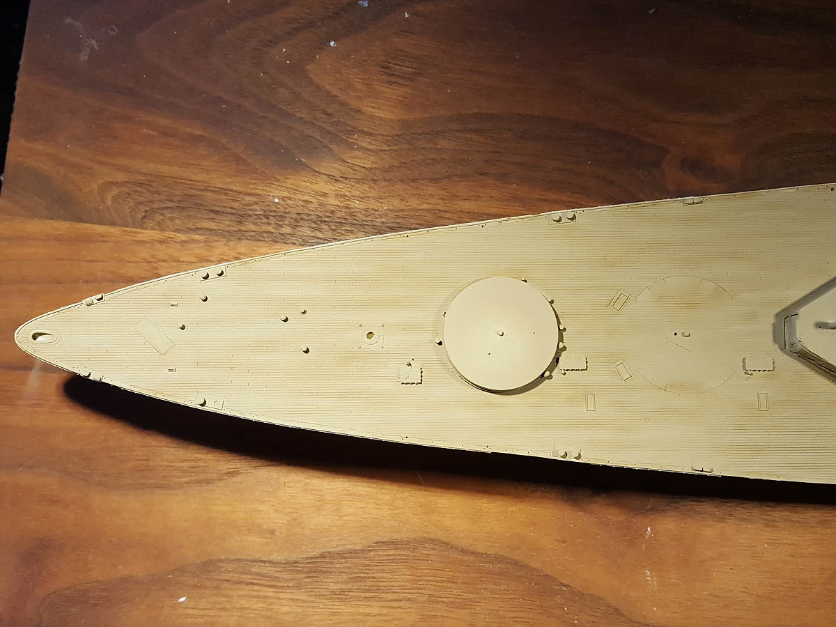
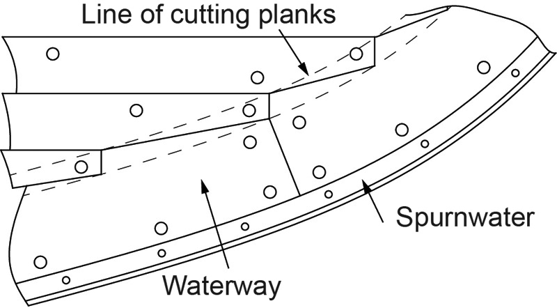
In the previous posts I discussed the deck details with margin planks, waterways, nibbing etcetera. The difficult part was getting the plank nibbing effect correct; if the spacing isn’t really regular it may show and scribing is quite tricky. You need to scribe a very small line of 1/3rd of a plank width consistently which translates to about 0.2mm; and then over 300 times for the entire ship. This kept me busy for many weeks and I experimented with various approaches, trying something new, failing, giving up, and then having another idea a few weeks later… and so on.

Approach one: Etched templates

This approach revolved around scribing templates that use the spurnwater as an reference edge; this strip was already present on the model (Plastruct 90709, wonderfully small! Go get some). Now, even drawing lots of these templates in CAD was a lot of work to do well so I made a small program in Matlab generating scripts and loaded them one by one in the etch drawing.

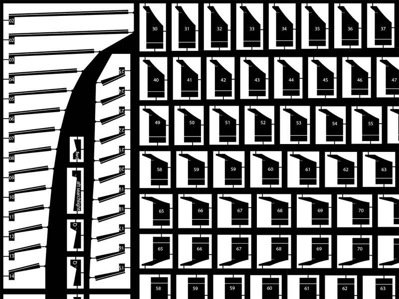
There are two templates, one for straight edges and one for the barbettes. I knew this might not work and sent in the etch anyway.

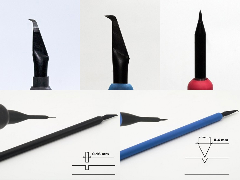
Meanwhile, I ordered three scribers from Uschi van der Rosten and started exercising scribing. I thought the fancy tips would work wonders to obtain a consistent result, but now I only use the needle scriber; I think that’s the only one you need and don’t drop it because you’ll need a new one. The etch came in and the results were… absolutely horrible. The templates are very difficult to hold, difficult to align, and scribing a 0.2-0.3mm line is just too difficult. When you are scribing you always need some lead way at the start and for 0.2mm you just don’t get any, you’re just poking the model. At this point I was fine with no deck details as I thought the technique was pretty far fetched.

Fortunately mother nature intervened a few weeks later when one of my cats took the protective cover from the scriber and tossed the Mr Scriber Narrow on the floor; the tip was broken off. What was left was a nice and small knife edge that gave a very thin line when pressed into styrene. I mutilated it a bit further into a 0.3mm wide tip, stared pressing small lines. The results were actually not bad… but also not good. I tried making more ‘chisels’, grinding down small screw drivers but it was difficult to get a nice sharp and mainly straight edge. I ordered the Grizzly H5915 Miniature Chisel set from Amazon for a few dollars but the quality was absolutely horrible; good thing I didn’t order them from Germany for over 50 Euros! I tossed them in the trash and dropped the idea again.

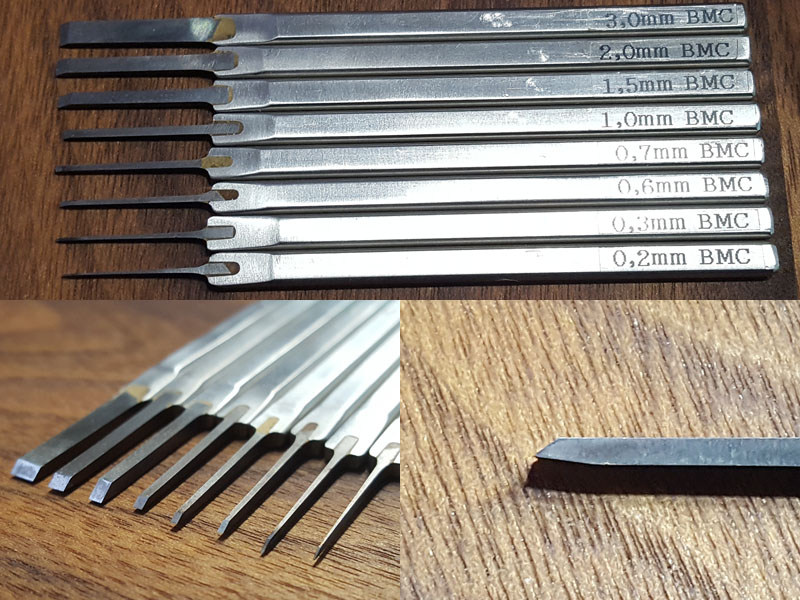
While searching the net I found these chisels by Sujibori-do; outrageously expensive starting at about €20 each—usually more—and that is without the import tax to that if you order them from Japan; they are also out of stock in most shops and you can find them well over €100 each on Ebay. But they come in a very nice range of exact widths in steps; the tip of the tool is made from tungsten steel and very, very sharp. With the flat stainless-steel grip they easy to hold without a holder you can order separately (not that I did so). They are so expensive it just had to work, right? I bit the bullet and ordered a few from Hobby Search. I started with sizes 0.2, 0.3, 0.6, 0.7, 1.0, 1.5, 2.0 and 3.0mm wide.

The tip of the chisel is asymmetrical and you need to tilt it back about 15 degrees when you press a line. I spent a fair amount of time practising on scrap styrene as you have to be careful to adjust the amount of force you exert;  the 3.0mm chisel requires too much force for making lines and you’d be better off using the 2.0mm or less. By pressing in the point you just push the styrene to the side, so you need to use the chisel as an actual chisel and remove the excess styrene carefully. For this job the 3.0mm chisel was really much more useful than the others. Giving a scratched line a correction pass with the widest chisel improved the overall line quality. Removing excess material was very dangerous at first, because if you apply the tool too steeply you’ll carve a channel in your deck, but this was a matter of some practice.

Now that I have these chisels I use them for cleaning up other parts, sharpening cut-out corners, making small corrections, putty knives (boo!). In fact, I consider them as one of the most useful additions to my arsenal of modelling tools and even ordered a few more and now have the complete set minus the two I dropped, that is… Oh well, live and learn.

Approach two: Guidance template

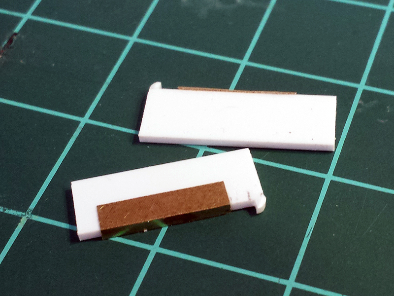
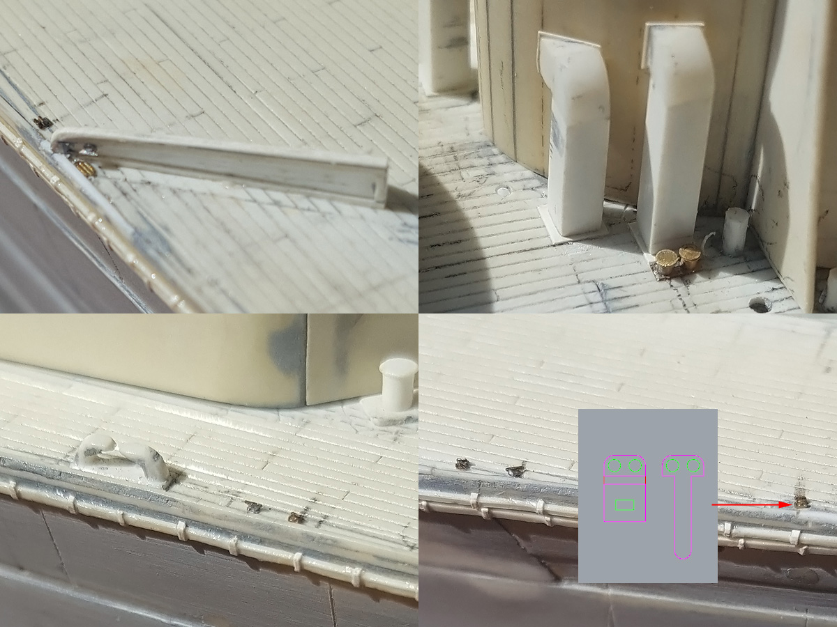
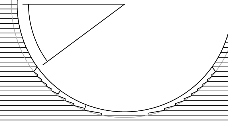
I devised a new strategy with my scribers using a small template to get the margin planks consistently. It’s basically of a small styrene strip, a small circular spacer at the end to hit the spurnwater at exactly the right distance no matter the angle of the deck, and, a small brass strip that drops just below the styrene strip to follow the V-groove in the deck; note that the brass doesn’t go up entirely towards the quarter circle because some on the deck line have been puttied a bit. Adding the 0.2mm line would be simply a matter of position the chisel at the quarter circle and pressing.

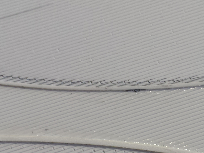
This worked really well on fresh, grooved styrene (this is even a 0.5mm spacing between planks, less than what I put on Hood). I thought it was really clever. But on the actual model, it didn’t go well. At all. The decks on the model are from the earliest attempts of my scratch-building and they have damage and corrections; the scribed lines are just not always deep enough for the template to follow. For very shallow angles near the center of the model the template would just ‘derail’… and that’s if the template can be used at all with a lot of deck detail already in place.

Approach three: manual labor

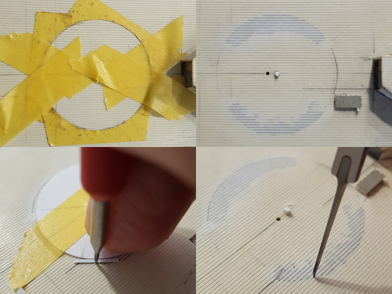
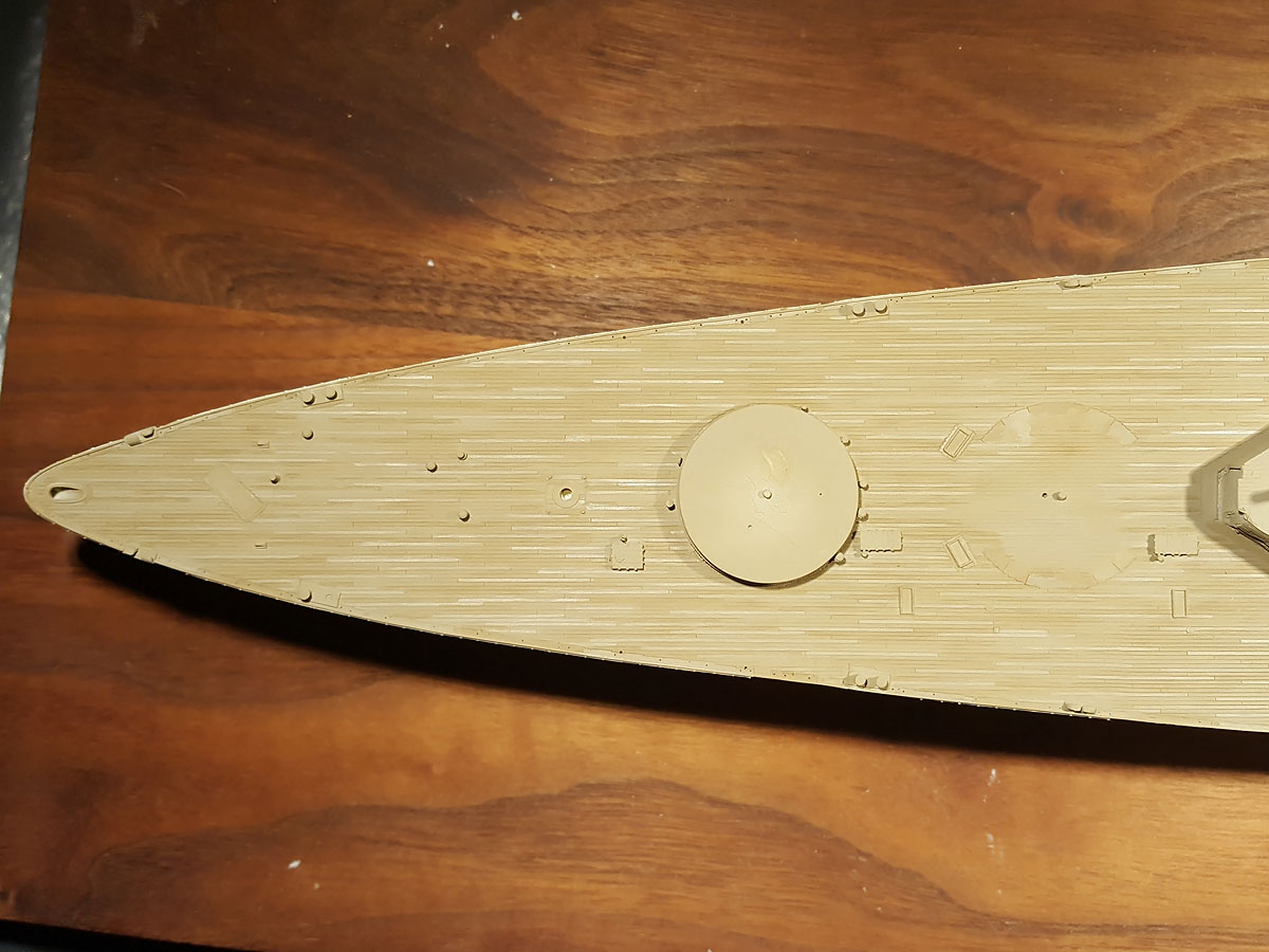
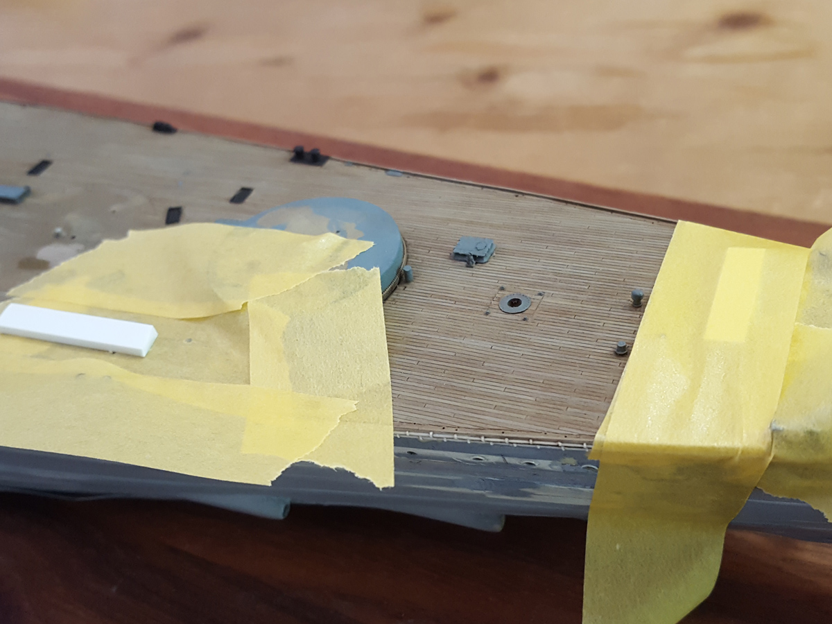
So in the end I came up with the stupid approach… basically this is a departure from using clever templates and relying more on my own skills. The margin plank is first taped off and puttied; after removing the excess putty the plank lines were well visible, so I just took a spacer strip and created a marker by gently pressing at the right position using needle scriber, or later, only using a very very fine pencil to outline the intersection line. The 0.3mm chisel was then placed at the marker, eyeballing the right position, and a small line was pressed in. Once all the lines were added it was simply a matter of connecting them with the other chisels and scribing for the longer planks. Excess putty can be removed easily from the grooves with the needle scriber. After scribing in the line I’d typically give the entire nibbing line a pass with the scriber to really connect all of them, clean up a bit, prescribe and re-chisel, clean, putty errors and repeat. Repeat again and repeat the repeating some more.

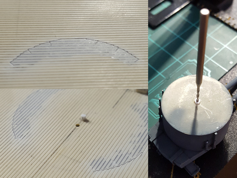
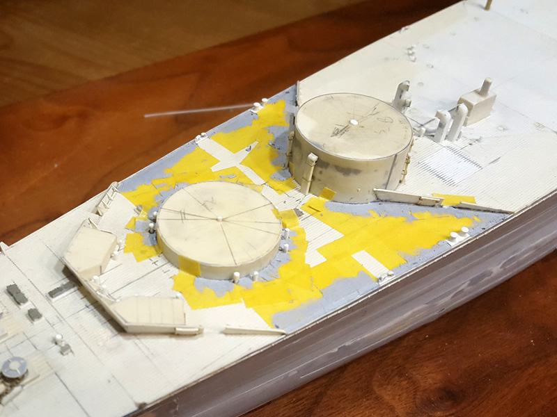
And once you have added the lines and cleaned up the parts I found out that one turret was poorly centred and needed so more work. The barbettes already glued to the deck were properly centred and this problem was found for one turret only. However for the barbettes glued to the deck it was really difficult to add in the lines with a lot less room to work with. This result is actually quite acceptable.

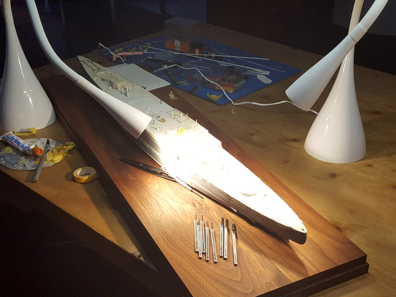
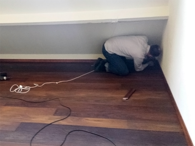
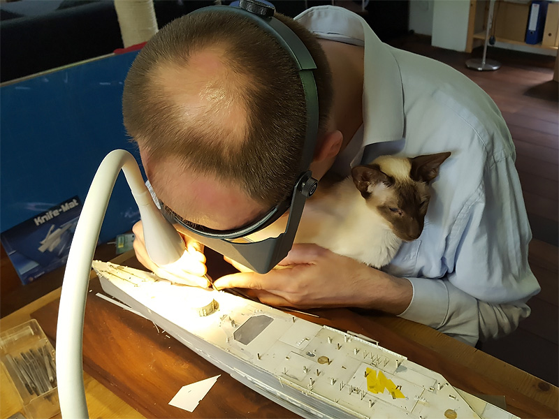
Now that the days were getting shorter and the weather turning for the worse, I could not really continue without good visibility, even with my 10x Optivisor. I got two semi-cheap LED lamps from the hardware store that give a lot of light for nearly no heat (!), plus, they are very slender and are really easy to place on the modelling table. Excellent additions long overdue.

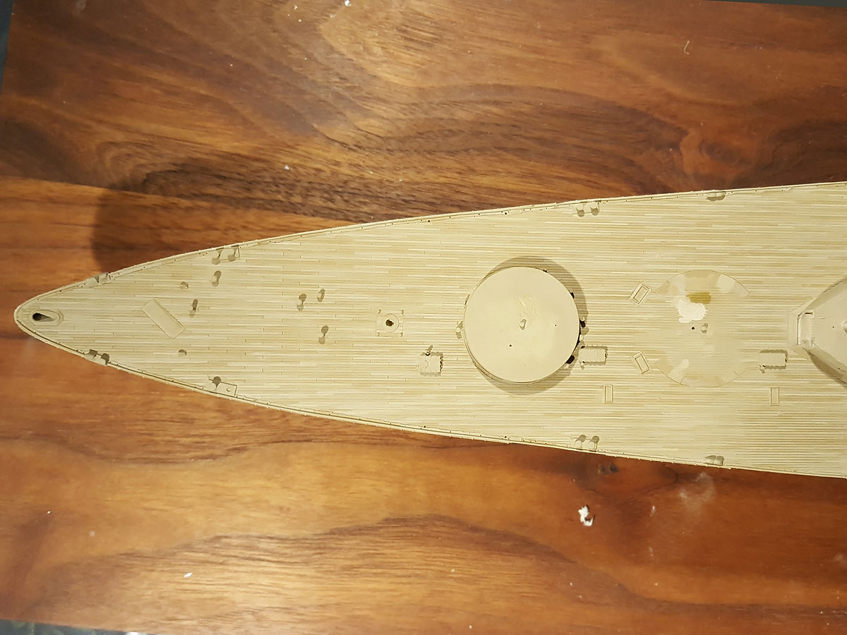
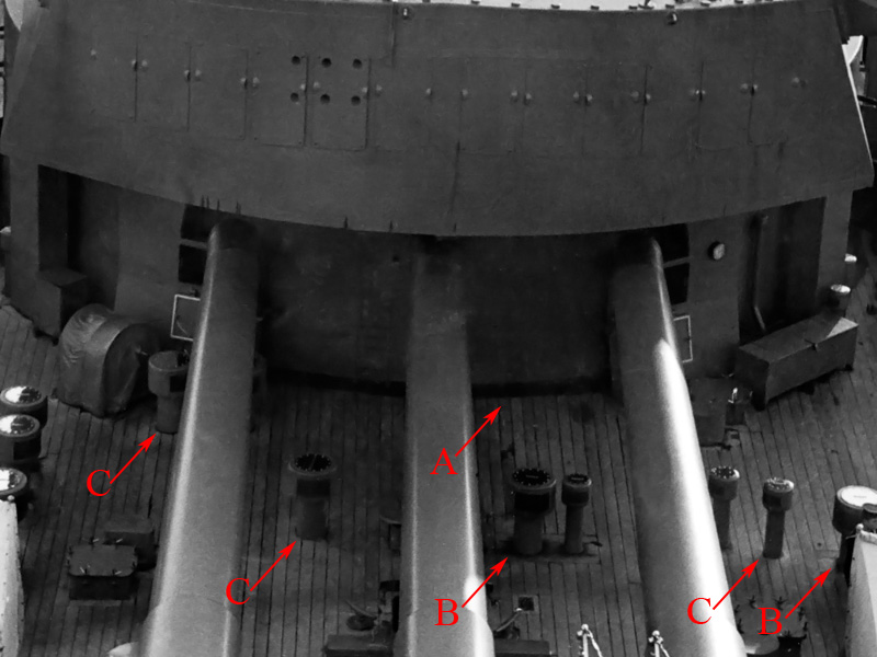
Now it’s simply a matter of puttying the margin plank areas and adding the scribing detail. The breakwaters proved to be difficult to work around, so they were eventually.. destroyed…

After the nibbing was added I took the 0.7mm chisel and added the plank ends. These typically aren’t too well visible on the real ship, but I thought they would be very useful to add when I need to paint the individual planks. Here the trick was not so much the chiselling but marking the lines by pencil with all the parts already glued to the deck. This would have been much easier if I had done this at an earlier stage of the build. There is nothing below most of the 0.5mm styrene plate of the boat deck, so I had to be careful not to puncture through the deck. The work crawled on hour by hour and the deck of Hood seemed to stretch on forever… each modelling session progressing a few inches.

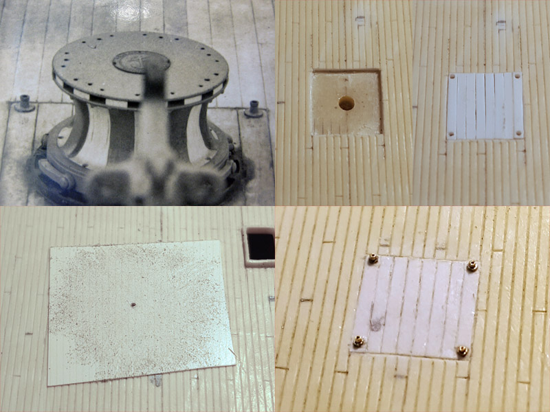
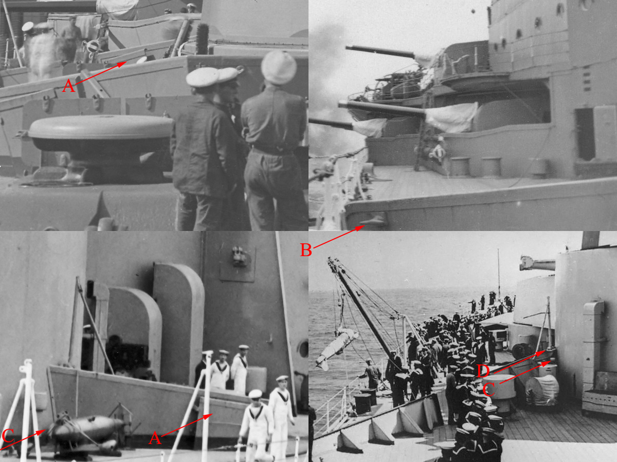
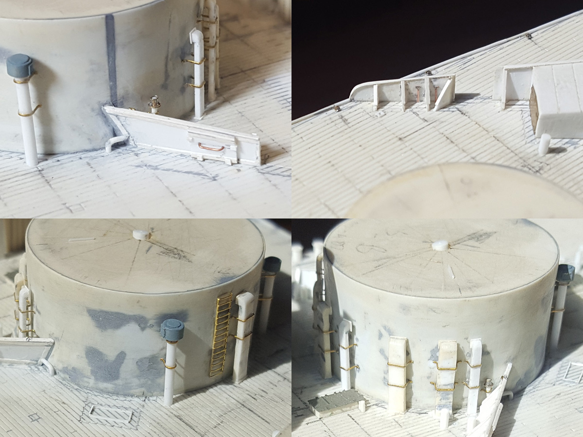
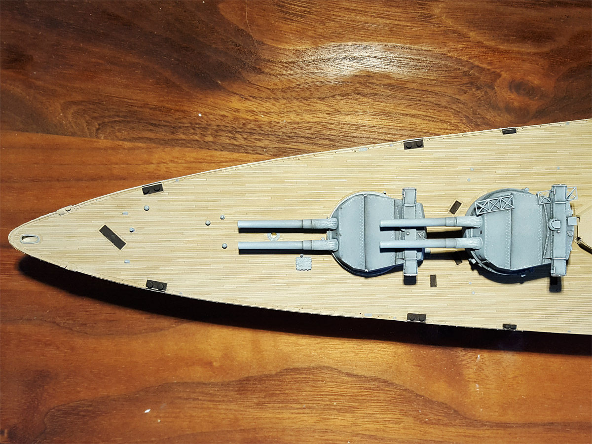
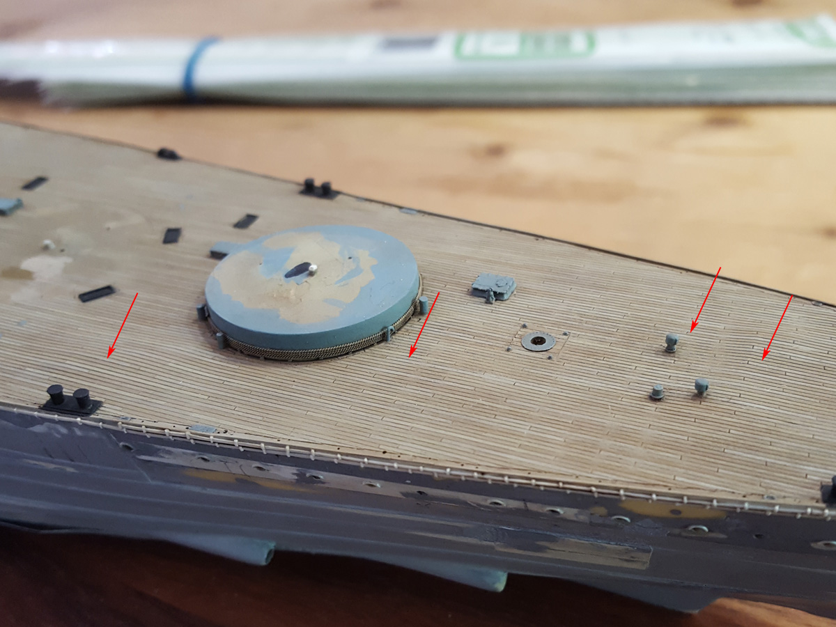
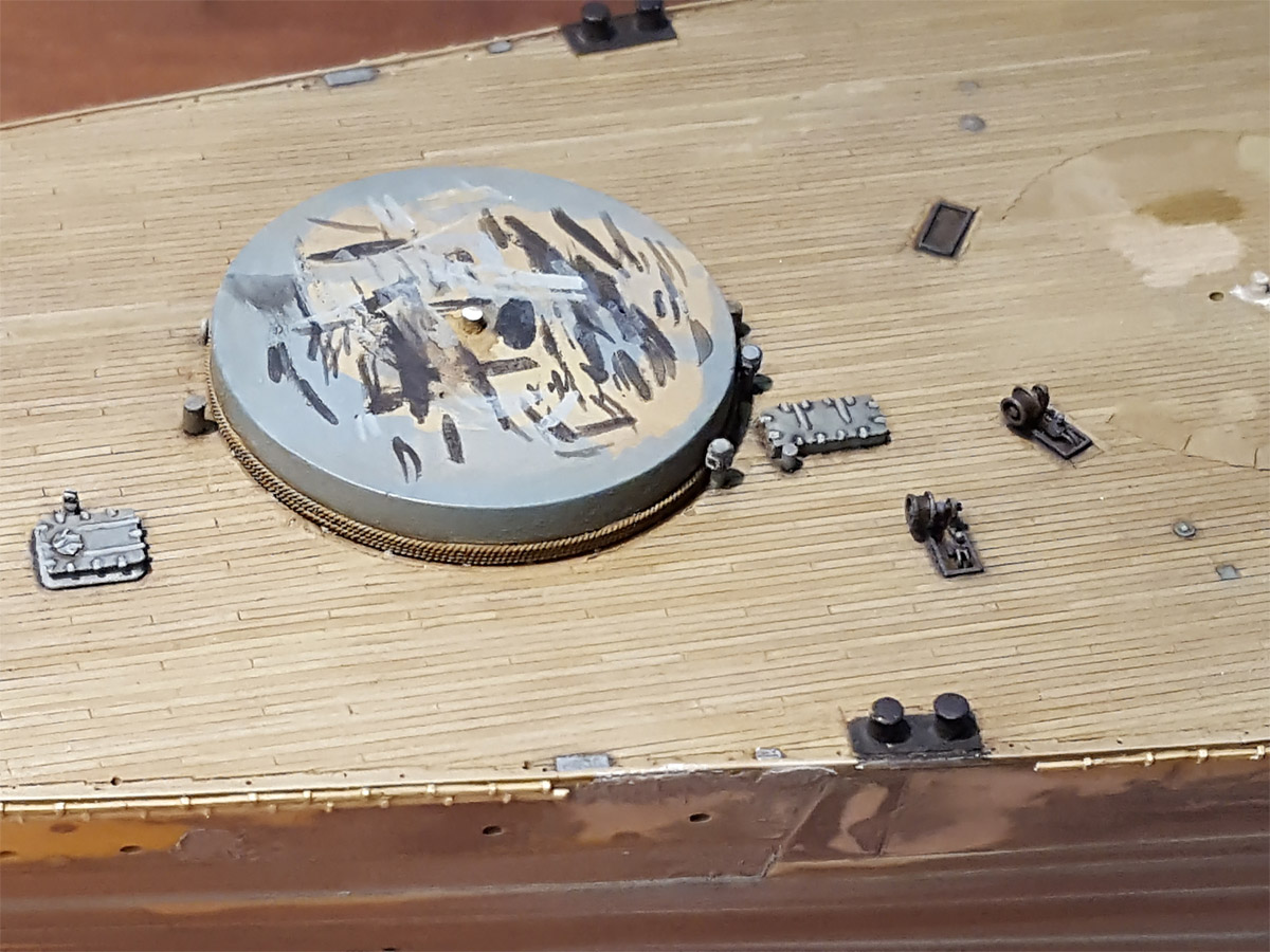
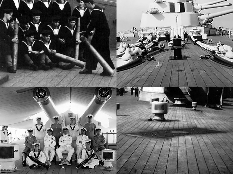
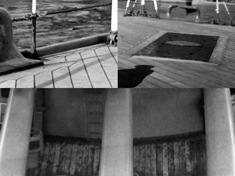
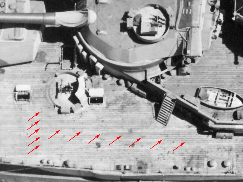
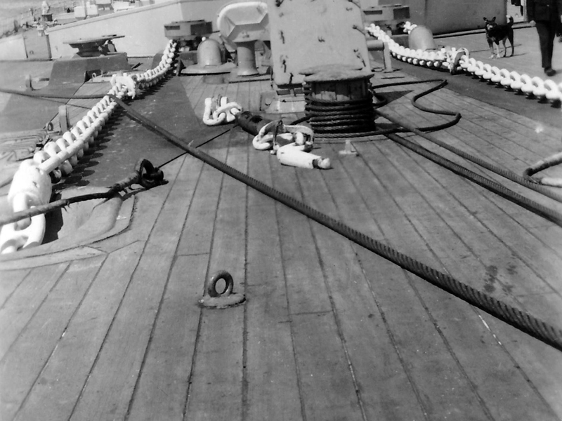
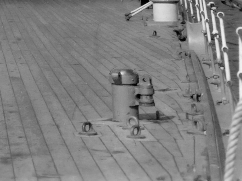
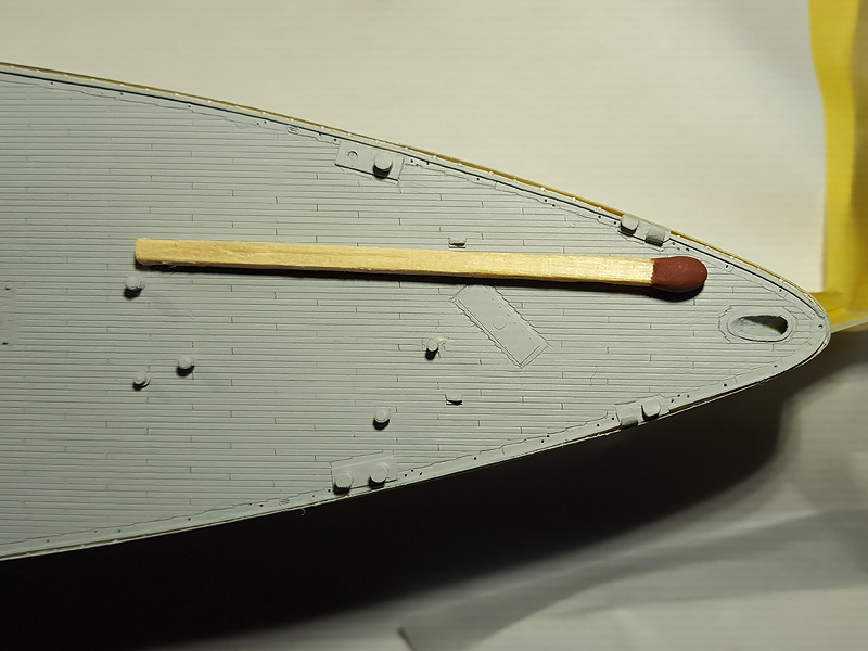
A nice image I received from the Hood association showed that the planking near the aft capstan was a bit different with a wider plank length. I cut out part of the deck and added new planks. I added some tubing by Albion Alloys to simulate the deck details. Note that with the use of a plastic strip you can very easily sand down the tubes to a consistent height.

The breakwater need to be re-added under very difficult circumstances.

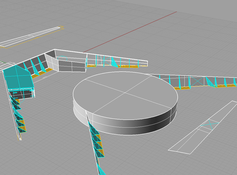
I decided to draw the breakwater in 3D in Rhino first; really useful to get all the parts to size and having a reference for future use.

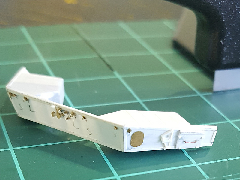
Adding all these deck details and replacing the breakwaters proved to be a huge delay for finishing the model… but the new parts look a lot better!

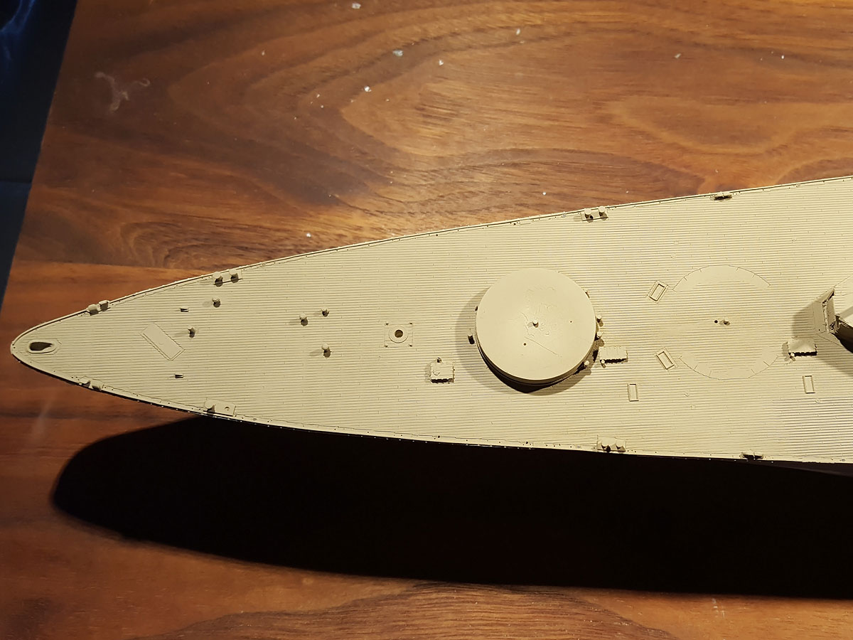
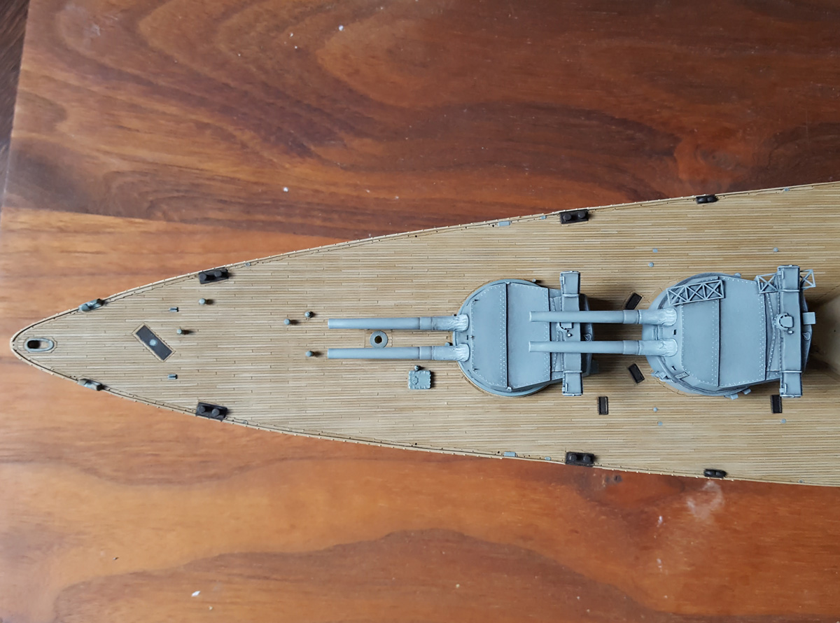
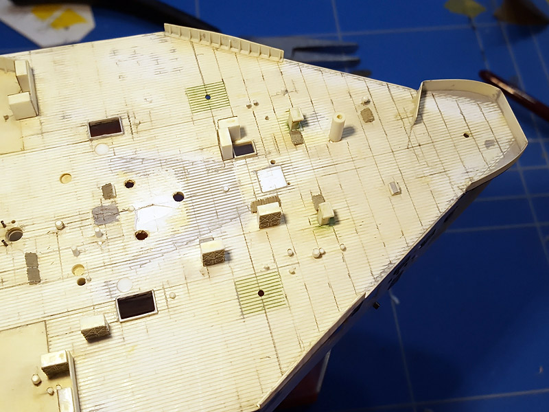
The centre and quarterdeck received a layer of Tamiya primer, nicely showing the result. The margin planks at the deck edge aren’t perfect but I’m satisfied. Note the scuppers and the many 0,25mm holes in the waterway where I intend to add individual stanchions and awning parts. I still need to add the second breakwater and add all the edge details to the forward and boat deck, but the vacation is nearly done. The next item will be painting in the individual planks of the deck just painted this morning…

It’s interesting to see the level of effort required between adding a glue-on lasercut decks by Pontos of Artwox (unfortunately rumoured to close its doors) and doing it yourself; these aftermarket sets add an enormous amount of detail to a model beyond anything I’ve seen until a few years ago. Adding this detail yourself is (nearly) prohibitively time-consuming and certainly not suited for leisurely paced modelbuilding. I guess it’s my way to relax, slowly going nowhere…

Ever more deckersizing

In my previous decksercising post I more or less stampeded over the details of the planks at the deck edge and received some comments from John Tennier, followed by drawings and documents, to underline I was missing a few key aspects of the deck (which is a polite way of saying I completely missed the point and rightfully so). I left the deck information to simmer for a while, having a bit of a modelling burnout due to a combination of circumstances making 2015 a poor year.  I did plan to spend most of my vacation days around last Christmas picking up the modelling but ended doing mainly more work and the rest of the time, well..

the deck of the hobby room needed some repair after the north wall was modified when our house was refitted, so here I am adding the last bit of the spurnwater in the hobby room and relaying the deck using a mix of salvaged planks and new ones. The fun part is that we need to do the other half this Christmas vacation… But I’ve gathered enough patience to absorb the onslaught of tiny modelling disappointments when trying out something entirely new, such as “perfect” decks details. Naturally, you can buy these wooden decks you can glue to your kit, but there are many reasons why I do not want that; the contrast in the decks lines is too high and I prefer the hand-painted deck look. Plus, I build my models to scale and not to fit some kit so it’s not really an option to try such a deck anyway.

The documents John sent me were “Shipyard practice as applied to ship construction” by Neil McDermain and a CAFO on deck coverings. Most of the info below is ‘recycled’ from these documents. The length of the plank is generally 24ft, or, 20.9mm on 350 scale. Planks are between 2.5 to 3 inches thick and 5 to 9 inches wide (5-7: CAFO, 9″ McDermaid), though the Anatomy of the Ship drawing I1 states that the planks aboard HMS Hood were 9 inches wide. That translates to slightly over 0.65mm wide on 1/350 scale. Now, I applied Evergreen 2025 V-grooved styrene to simulate the deck with a spacing of 0.25″ (or 0.635mm) that is just perfect.

Now, if I look at the image above and the what I assume to be a 4″ shell as a reference I get a plank width of about 8″ so that’s a actually bit less. The rest of the smaller images using distances between vents and such result in 7.6, 8.15 and 7.0″ when compared to the AOTS (The last one is a bit lower so perhaps that angled plate was not entire drawn properly to scale in the AOTS?). So, the actual plank width was probably much closer to 8″ than 9″ and we would have wanted a 0.58mm spacing. The only alternative I know of for a deck plate is Evergreen Car Siding 2020 that leads a (scaled) plank width of 6.9″ so the 2025 is actually less wrong and even if it weren’t, replacing the decks would be worse than just starting the entire model over from scratch.

On the edge of the deck with the hull there is a waterway that is laid first and is 15 to 18″ wide. For the ship the planks are laid in the centreline first and the position of all the planks is marked on deck. The planks are bolted to the deck on studs fastened to the steel deck. The plank end would be too fine for fastening and caulking if it were simply cut off at the waterway intersection, so a cut is made about third of the plank width into the waterway perpendicular to the plank and then connected where the waterway and plank first meet . The result is a nice nibbing pattern.

The pattern of nibbing around deck fixtures is not consistent between ships; the top left shows the nibbing around the bollards where a margin plank was present at the short end of the bollard emplacement, but not so for HMS Hood. The top-right image is from HMS Hood, showing the nibbing of the aforementioned quarterdeck deckplate. The lower image is of HMS Rodney; here the nibbing of the planks does not follow the barbette everywhere; there is not even a margin plank.

Margin planks are present at the flanks of the barbette but at what angle they stop differs between drawings and is very difficult to spot on photographs. For my model I simply took the 37 degrees as in the Anatomy of the ship.

This wonderful aerial shot of HMS Queen Elizabeth shows the deck details clearly and there is much to see. Note how the ends of the planks align really well and that there are 4 planks between planks with matching ends. The staggered pattern continues throughout most of the deck. Although it’s not too well visible, it appears the pattern does not continue between the barbettes, as you would expect with a barbette a large interruption of the deck planking. Very large margin planks are visible around the hatch coamings and bollards.

This is a KGV-class, showing the margin planks around the hawse pipes. Chafing plates preventing damage to the deck by the anchor chain really lie on top of the existing planking and no nibbing is present. The hatch a bit further down in the distance does not have visible margin planks (the hatch coamings in front of the breakwaters and on the quarterdeck were fitted ‘blast plates’ angling out at 45 degrees and other hatch coamings may have other styles?).

The breakwater is slightly more complicated and I do not have good shots of HMS Hood’s. On this shot of HMS Rodney it appears there’s a wide ‘margin’ plank present at the breakwater right and the planking pattern continuing at either side. There is no nibbing present.

However, the other end shows some more detail. A few more planks are visible behind the second breakwater of HMS Queen Elizabeth, Rodney, Prince of Wales and an unidentified ship, with three planks fitted beneath the breakwater and its supports. Tricky, as my model is already fitted with a breakwater and I agreed with myself not to destroy anything (anymore).

A few minor details (Rodney) with no margin plank at the rear of the barbette (A). For the various deck fittings it appears sometimes there is a margin plank (B) and sometimes not (C). This leaves some artistic license when detailing the deck.

HMS Rodney again; near small derricks and eyelets the details appears to be quasi-random. The shot of HMS Hood’s anchor arrangement four images up shows not such planking around an eyelet. The plank nibbing is particularly well visible.

How to actually add all the deck detail is for the next update.

Copyright © 2024 On The Slipway

Theme by Anders NorenUp ↑