Month: December 2008

Making rings with a Punch & Die set, part II

I posted a small tip how to make rings with the punch and die set (here). I made a small refinement that allows for the punching out of holes from rod or disks. For this, I used the Waldron Sub Miniature Punch & Die set (any set will do). I would advice people who want to do scratchbuilding to buy both Waldron sets (or make their own).

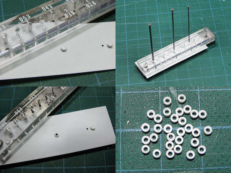
1) Take a styrene strip with a hole so that it can swivel around the pin of the set. The strip should be as thin as or thinner than the working material.
2) Place the strip in the set and punch out three holes. One hole is for the working disk, the other two for positioning. Do not remove the punches until all three have been used.
3) We now have a simple template that can be repositioned using the two outer punch holes.
4) Now, drill the center hole to the exact diameter of the working material. I also added to holes at the far ends of the strip and added two disks with the same height as the disk.

5) Insert the disk into the center hole and press it so that it positioned tightly.
6) Position the styrene strip and fix it using  the outer punches for the exact location
7) Gently punch out the center of the disk and remove all punches. Swivel the strip outwards and remove the ring.
8) Make many!

The advantage of this technique is that it works for all combinations of inner (depending on the punch & die set) and outer diameters. You only need to have the exact drill size ready, which is much easier than making sub punches on a lathe as with my previous tip.

Update added 18-01-09

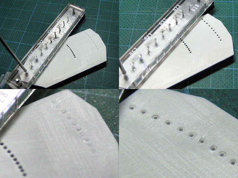
A small refinement was added to this tip. I let the styrene strip swivel around the largest punch. The second punch is taken to set the strip into position with the third punch for the actual punching. The pic shows I use an array of holes. Top left shows the positioning with the smallest punch. At top right the holes are drilled in where the rings can be positioned. Bottom left shows a series of 10 disks in place with the result shown at bottom right. From the close-up is visible that not all rings are concentrically, so you need to throw away some of them. I also marked which side of the mould is up, as reversing it results in all rings being punched off-center.

Octuple pompoms, part I

HMS Hood has three older octuple 2 pounders, or pompoms for short. I already made a few of these models a few years back based on the drawing L/0/66 of John Lambert Plans. I even included a few etched parts.

This is the first model on the band stand on the boat deck. Looks quite good and has sufficient detail. But, two things were constantly bothering me. One, I’d found a good source of tubing from Cammet Ltd with the right size of tubing for the barrel and the cooling sleeve while this one has solid rod, and two, the newer commercial etch sets have a nicer floor representations and even ammo belts. Even though the commercial etch sets have lots of errors (lots), I feel I can do much better.

So, I spent a few days going over the drawing by John Lambert, the Vickers Photographic Archive, and some assorted pictures, and made new parts in Autocad for etching. This will be quite an interesting folding exercise! A bit of random detail will be added to the model but it’s mainly etched parts. A second larger etch is in the works which I hope to have finished soon.

Vents, part I

A series of boiler room vents runs through the bridge superstructure and next to the funnels. On all the drawings, two boiler room vents are drawn at the bridge location, but only one of them visibly exist the superstructure on the admiral’s signal platform. So, where does the other one end up? The top left section of the image shows the rear of HMS Hood’s superstructure, with the arrow indicating the exact location of the after boiler room vent. The other vent is seen on the image section next to it. The top right image shows the implementation on the model. I’m not exactly sure if the aft vent is correct, but this is all the material I have. The bottom half shows both vents in detail. The vents on the admiral’s signal platform intersect the base of the 5.5″ rangefinder towers.

There are four large engine room vents on the boat deck, all situated on the center line of the ship. The top left image shows a sailer posing with one of these vents in the background. A little to his right, the vent near the searchlight platform is visible. Notice anything? This vent is considerably taller than the other vent, which is not indicated on any drawing of HMS Hood. The other pics show the same vent in detail. It’s very easy to overlook the height of this vent, until you actively gauge its height from nearby details. It’s nearly twice the height of the sailer standing in the top right image. The top left image shows that a series of hatches are present on the top of the vent, including a small ridge around it.

This image has the location of the vents indicated. Notice that all hatches on top of the vents are opened toward the stern of the ship. It’s difficult to make out the outer right vent and I can’t tell if hatches are present. Probably not, as the main derrick is stored on a crutch on top of this vent, blocking the hatches from opening. The vent near the disinfector house (second from the right) is also blocked by the main derrick, but is built wider with hatches capable of opening when the main derrick is stored. This might be true for the vent at right as well, but I cannot find any picture showing this, with all the boats and launches stored there blocking the view. If hatches are present, I’ll add them afterwards as I’ll have the main derrick in the stored position on the model.

Here are the vent models that took a surprising amount of time to complete. I started by cutting strip to size, added wire mesh, cut the strip to height and width, and glued them to a rectangular base. A small 0.25mm strip was glued to each corner. The roofs are frameworks of 0.25mm strip as well. Small triangles were added to the corners of the mesh (difficult to do) and custom-etched hatches were added later. The hatches are fixed using arced supports, visible when stored in the top left of the previous image (behind the sailor).

Copyright © 2024 On The Slipway

Theme by Anders NorenUp ↑