In my previous decksercising post I more or less stampeded over the details of the planks at the deck edge and received some comments from John Tennier, followed by drawings and documents, to underline I was missing a few key aspects of the deck (which is a polite way of saying I completely missed the point and rightfully so). I left the deck information to simmer for a while, having a bit of a modelling burnout due to a combination of circumstances making 2015 a poor year. I did plan to spend most of my vacation days around last Christmas picking up the modelling but ended doing mainly more work and the rest of the time, well..
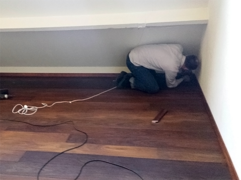
the deck of the hobby room needed some repair after the north wall was modified when our house was refitted, so here I am adding the last bit of the spurnwater in the hobby room and relaying the deck using a mix of salvaged planks and new ones. The fun part is that we need to do the other half this Christmas vacation… But I’ve gathered enough patience to absorb the onslaught of tiny modelling disappointments when trying out something entirely new, such as “perfect” decks details. Naturally, you can buy these wooden decks you can glue to your kit, but there are many reasons why I do not want that; the contrast in the decks lines is too high and I prefer the hand-painted deck look. Plus, I build my models to scale and not to fit some kit so it’s not really an option to try such a deck anyway.
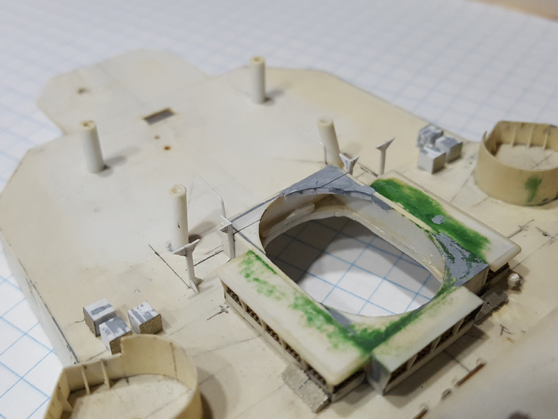
The documents John sent me were “Shipyard practice as applied to ship construction” by Neil McDermain and a CAFO on deck coverings. Most of the info below is ‘recycled’ from these documents. The length of the plank is generally 24ft, or, 20.9mm on 350 scale. Planks are between 2.5 to 3 inches thick and 5 to 9 inches wide (5-7: CAFO, 9″ McDermaid), though the Anatomy of the Ship drawing I1 states that the planks aboard HMS Hood were 9 inches wide. That translates to slightly over 0.65mm wide on 1/350 scale. Now, I applied Evergreen 2025 V-grooved styrene to simulate the deck with a spacing of 0.25″ (or 0.635mm) that is just perfect.
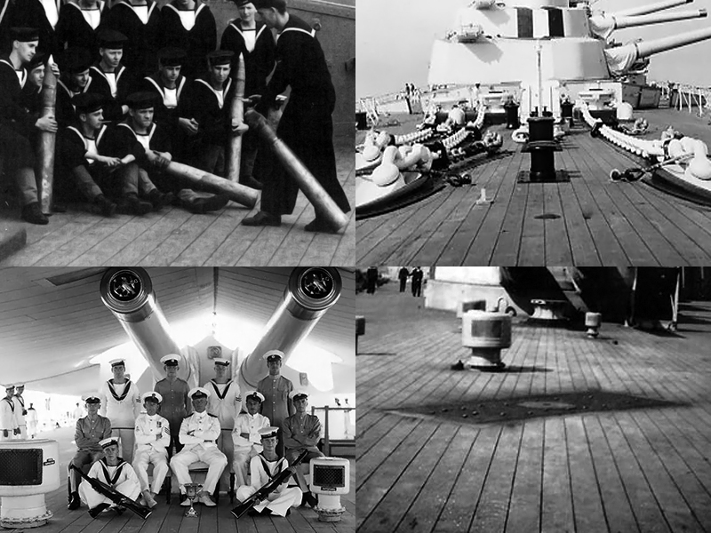
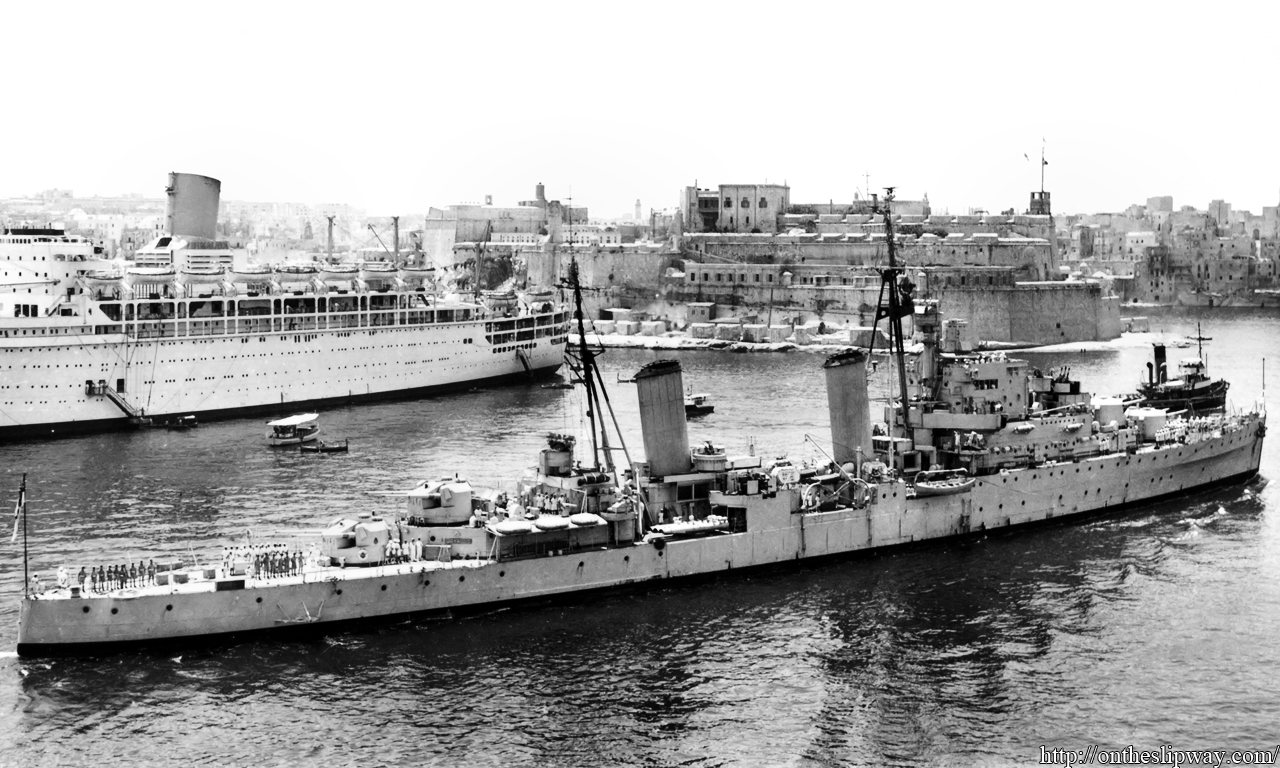
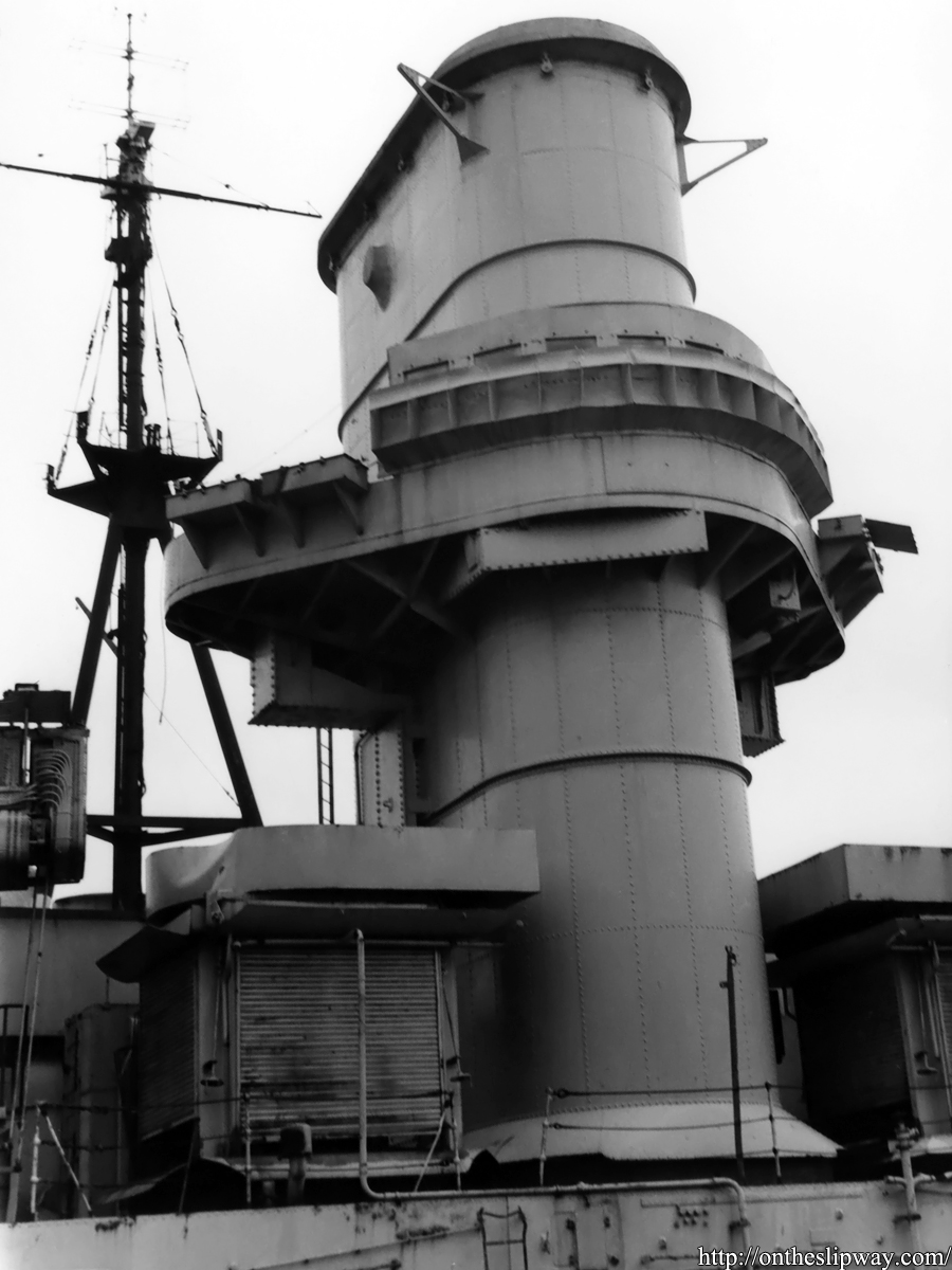
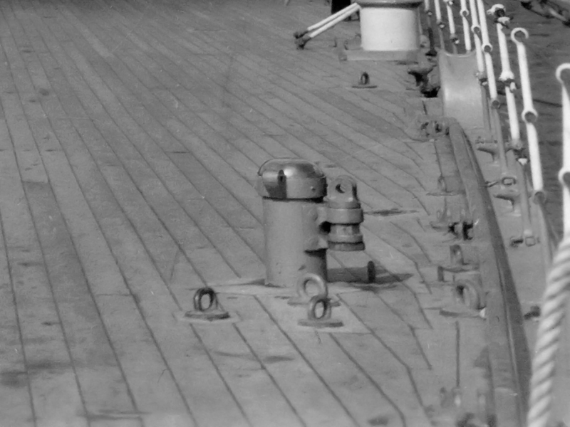
Now, if I look at the image above and the what I assume to be a 4″ shell as a reference I get a plank width of about 8″ so that’s a actually bit less. The rest of the smaller images using distances between vents and such result in 7.6, 8.15 and 7.0″ when compared to the AOTS (The last one is a bit lower so perhaps that angled plate was not entire drawn properly to scale in the AOTS?). So, the actual plank width was probably much closer to 8″ than 9″ and we would have wanted a 0.58mm spacing. The only alternative I know of for a deck plate is Evergreen Car Siding 2020 that leads a (scaled) plank width of 6.9″ so the 2025 is actually less wrong and even if it weren’t, replacing the decks would be worse than just starting the entire model over from scratch.
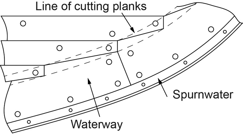
On the edge of the deck with the hull there is a waterway that is laid first and is 15 to 18″ wide. For the ship the planks are laid in the centreline first and the position of all the planks is marked on deck. The planks are bolted to the deck on studs fastened to the steel deck. The plank end would be too fine for fastening and caulking if it were simply cut off at the waterway intersection, so a cut is made about third of the plank width into the waterway perpendicular to the plank and then connected where the waterway and plank first meet . The result is a nice nibbing pattern.
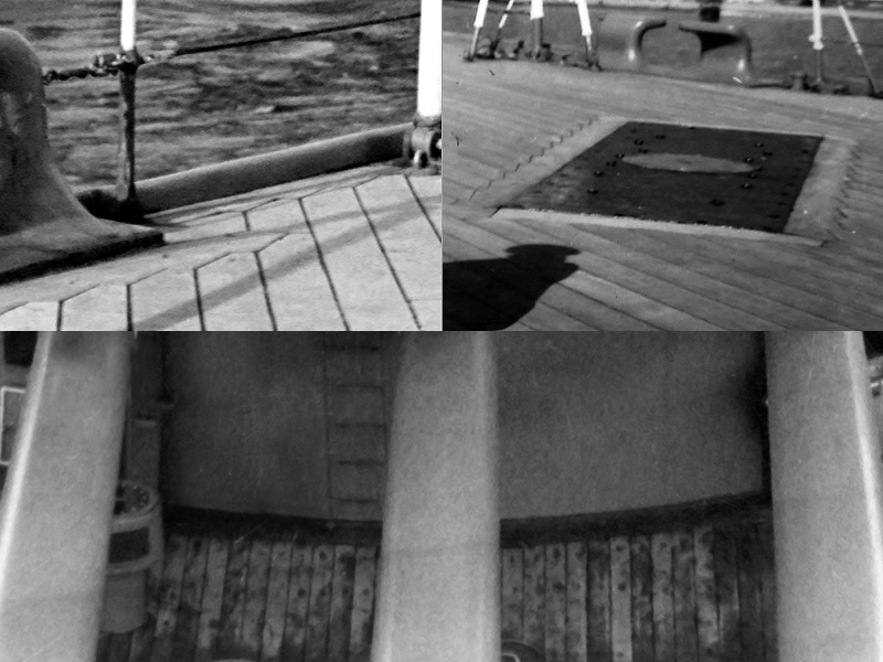
The pattern of nibbing around deck fixtures is not consistent between ships; the top left shows the nibbing around the bollards where a margin plank was present at the short end of the bollard emplacement, but not so for HMS Hood. The top-right image is from HMS Hood, showing the nibbing of the aforementioned quarterdeck deckplate. The lower image is of HMS Rodney; here the nibbing of the planks does not follow the barbette everywhere; there is not even a margin plank.
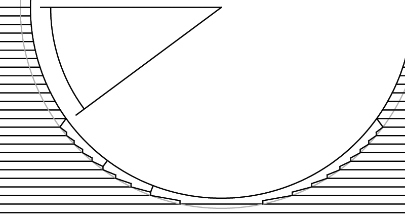
Margin planks are present at the flanks of the barbette but at what angle they stop differs between drawings and is very difficult to spot on photographs. For my model I simply took the 37 degrees as in the Anatomy of the ship.
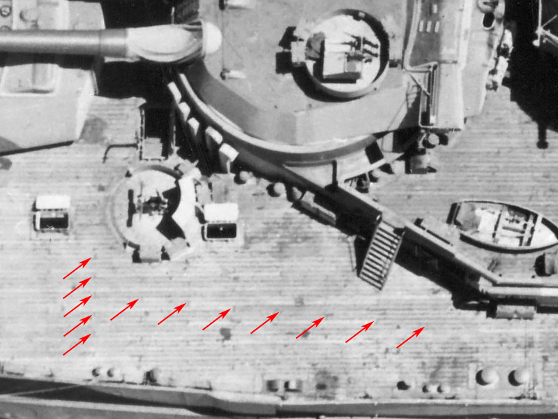
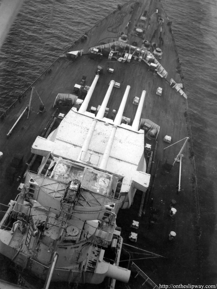
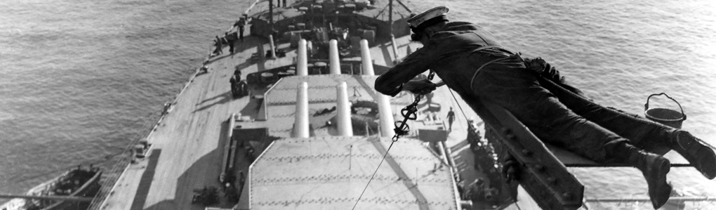
This wonderful aerial shot of HMS Queen Elizabeth shows the deck details clearly and there is much to see. Note how the ends of the planks align really well and that there are 4 planks between planks with matching ends. The staggered pattern continues throughout most of the deck. Although it’s not too well visible, it appears the pattern does not continue between the barbettes, as you would expect with a barbette a large interruption of the deck planking. Very large margin planks are visible around the hatch coamings and bollards.
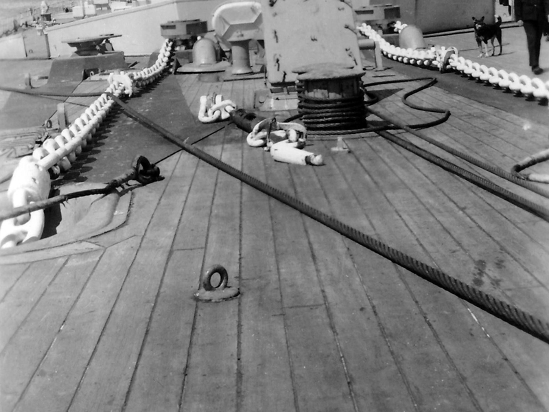
This is a KGV-class, showing the margin planks around the hawse pipes. Chafing plates preventing damage to the deck by the anchor chain really lie on top of the existing planking and no nibbing is present. The hatch a bit further down in the distance does not have visible margin planks (the hatch coamings in front of the breakwaters and on the quarterdeck were fitted ‘blast plates’ angling out at 45 degrees and other hatch coamings may have other styles?).

The breakwater is slightly more complicated and I do not have good shots of HMS Hood’s. On this shot of HMS Rodney it appears there’s a wide ‘margin’ plank present at the breakwater right and the planking pattern continuing at either side. There is no nibbing present.
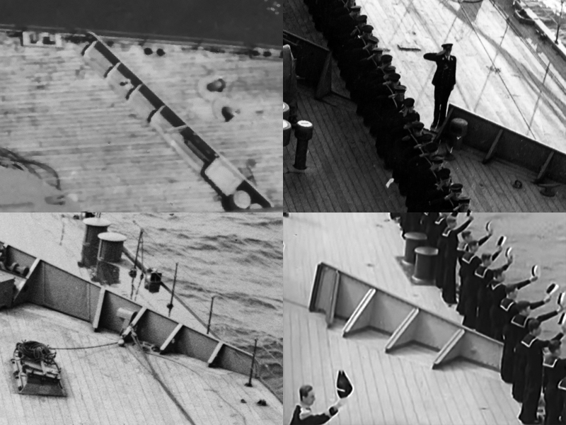
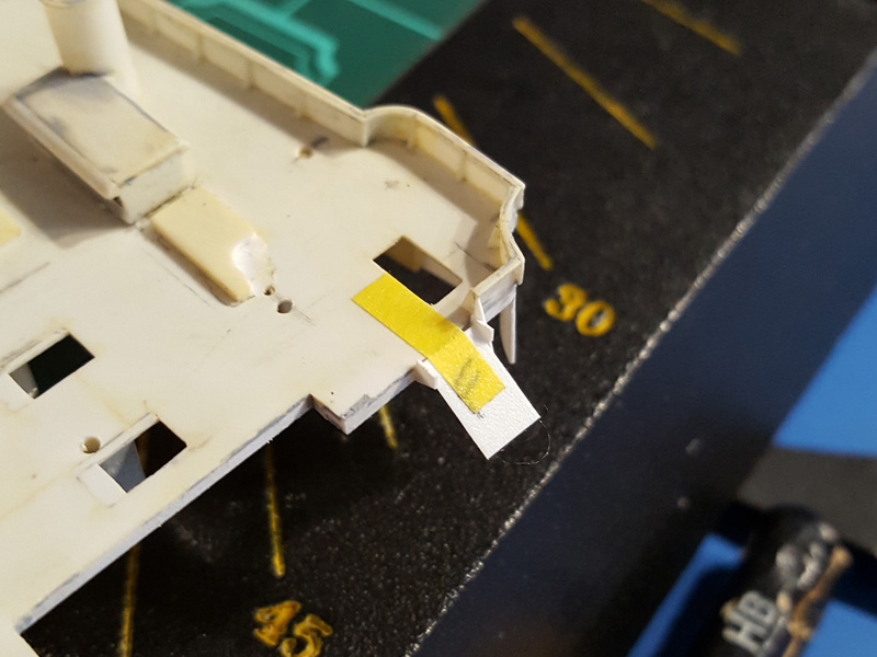
However, the other end shows some more detail. A few more planks are visible behind the second breakwater of HMS Queen Elizabeth, Rodney, Prince of Wales and an unidentified ship, with three planks fitted beneath the breakwater and its supports. Tricky, as my model is already fitted with a breakwater and I agreed with myself not to destroy anything (anymore).
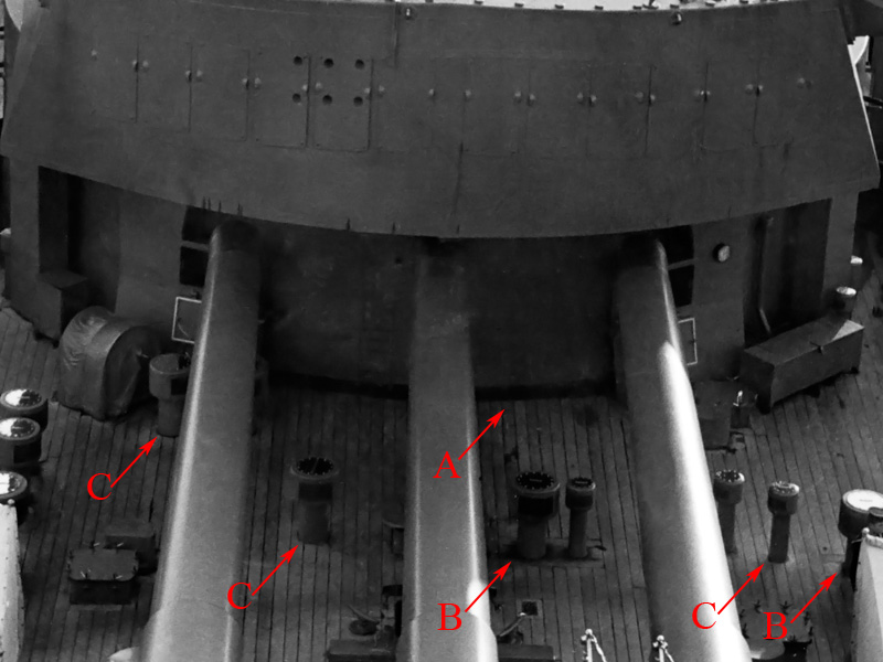
A few minor details (Rodney) with no margin plank at the rear of the barbette (A). For the various deck fittings it appears sometimes there is a margin plank (B) and sometimes not (C). This leaves some artistic license when detailing the deck.
HMS Rodney again; near small derricks and eyelets the details appears to be quasi-random. The shot of HMS Hood’s anchor arrangement four images up shows not such planking around an eyelet. The plank nibbing is particularly well visible.

How to actually add all the deck detail is for the next update.