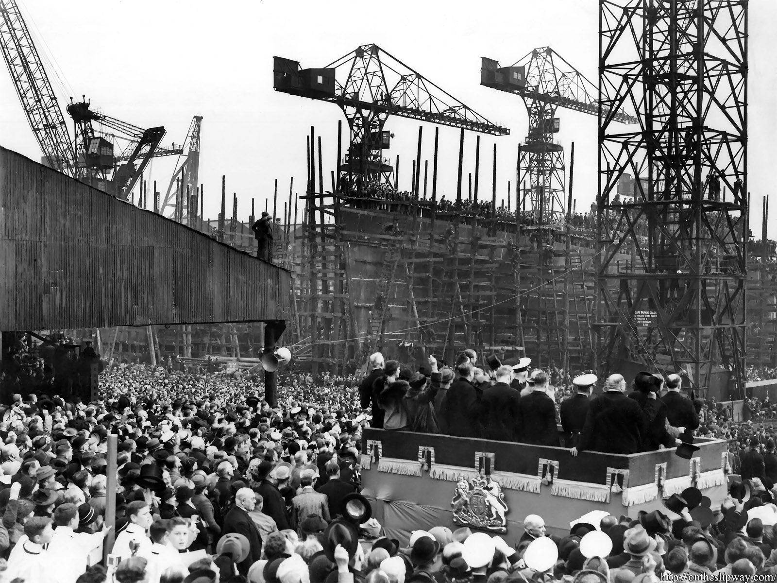
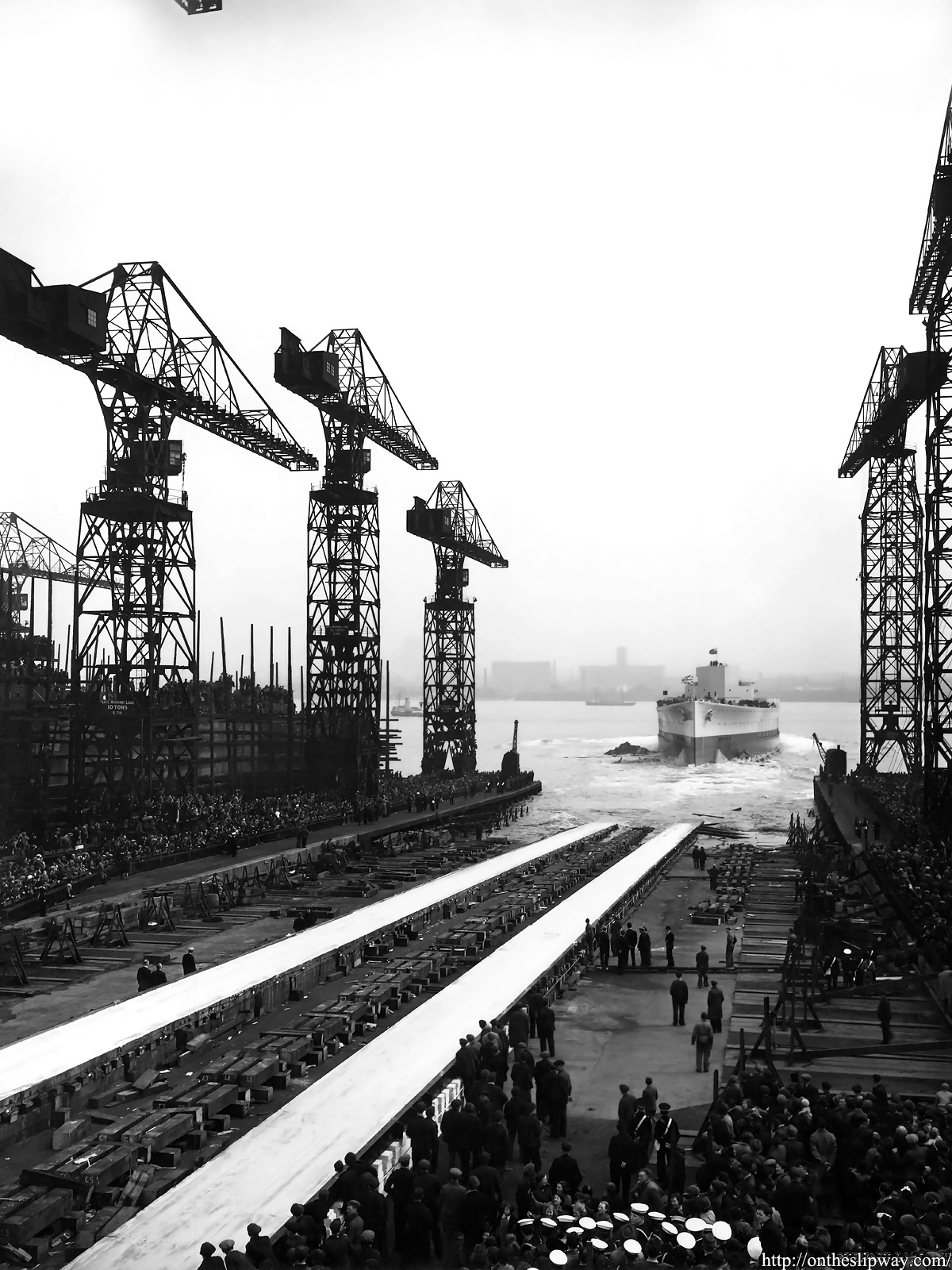
HMS Prince of Wales was launched at Cammell Laird’s shipyard in Birkenhead on Merseyside on the 3rd of May 1939. A number of photographs of the launching ceremony is being held by the Wirral Archives service; a number of these images show the keel laying ceremony as previously posted Laying the keel of HMS Prince of Wales.
A brief press clip can be viewed at British Pathe.I find this clip of particular interest as it mentions other nations not keeping to their treaty limits as well as the Royal Navy soon receiving three more ships of the same class Duke of York, Jellicoe and Beaty, (the latter renamed Anson and Howe), plus, the Lion-class battleships Lion and Temeraire. The keels of both of these ships would be laid a few months after HMS Prince of Wales was launched but work on both ships was suspended in 1940.
Please note these images have been reproduced with the permission of both BAE Systems and the Wirral Archives.
“Copyright © 2018 BAE Systems. All Rights Reserved. This work is reproduced with the kind permission of BAE Systems. BAE Systems is a registered trademark of BAE Systems plc”
I would like the express my gratitude to both the Wirral Archival Service and BAE systems both for their assistance and for making it possible to publish these photographs.
You can visit the Wirral Archival Service here:https://www.wirral.gov.uk/libraries-and-archives/wirral-archives-service
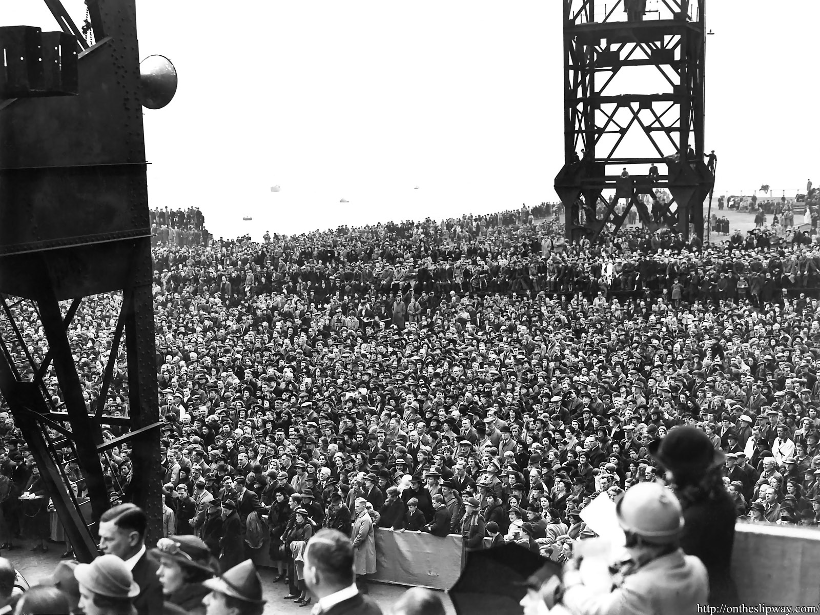
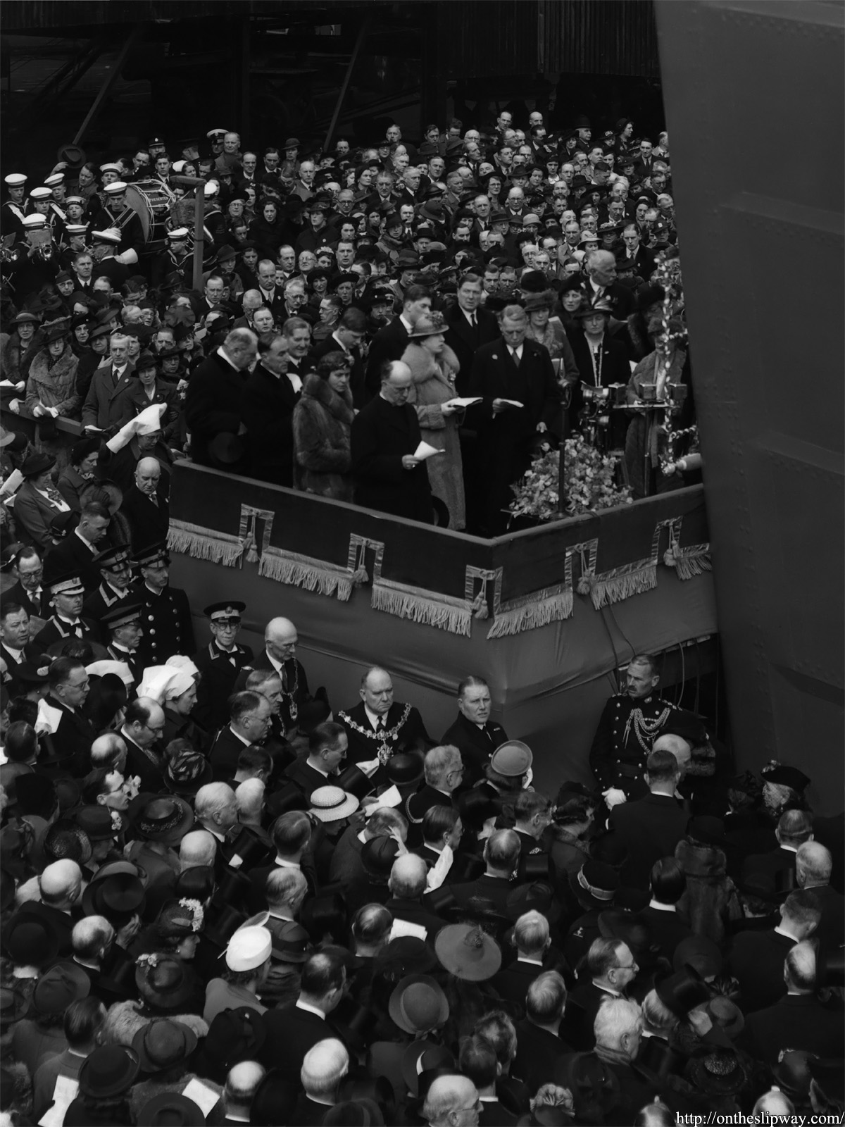
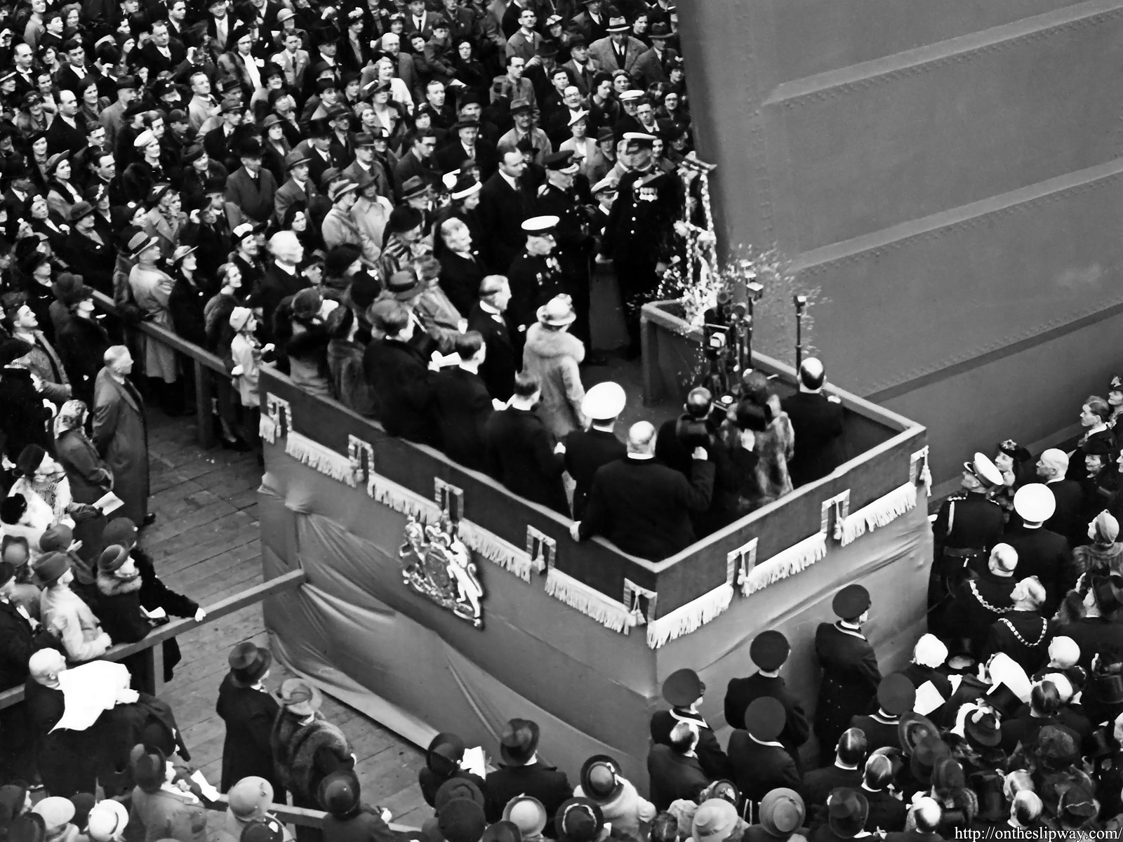
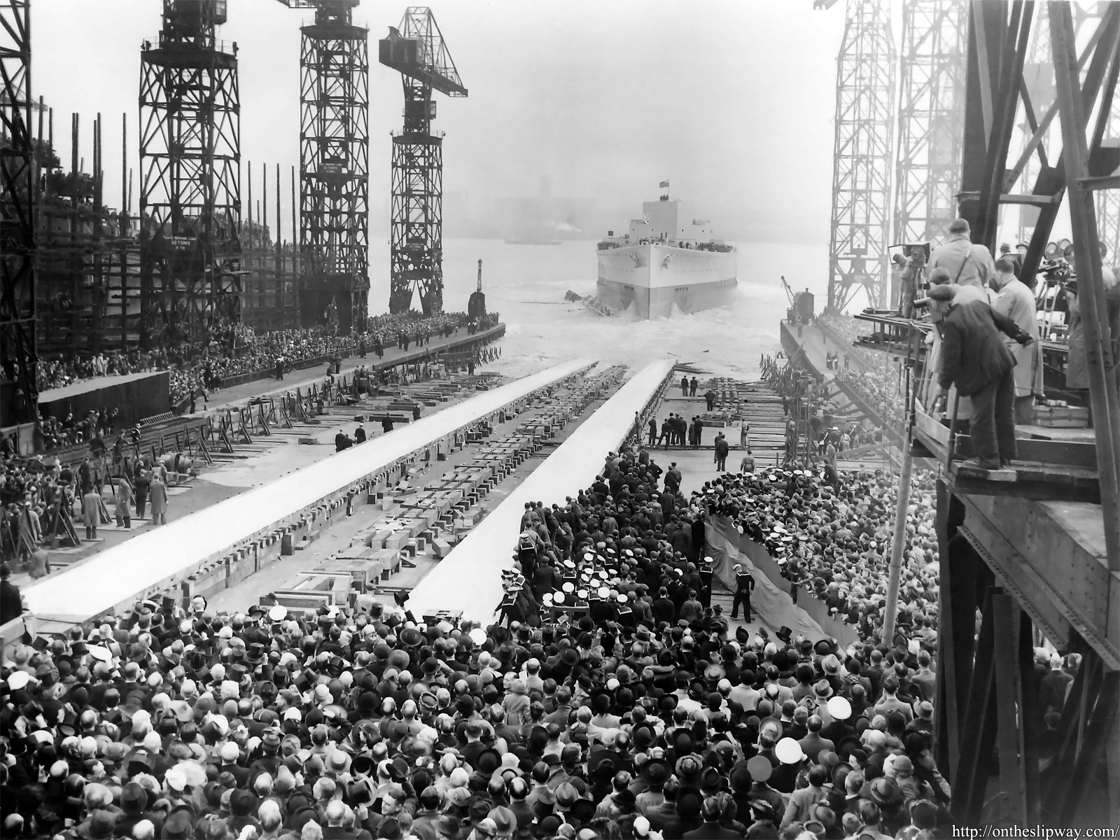
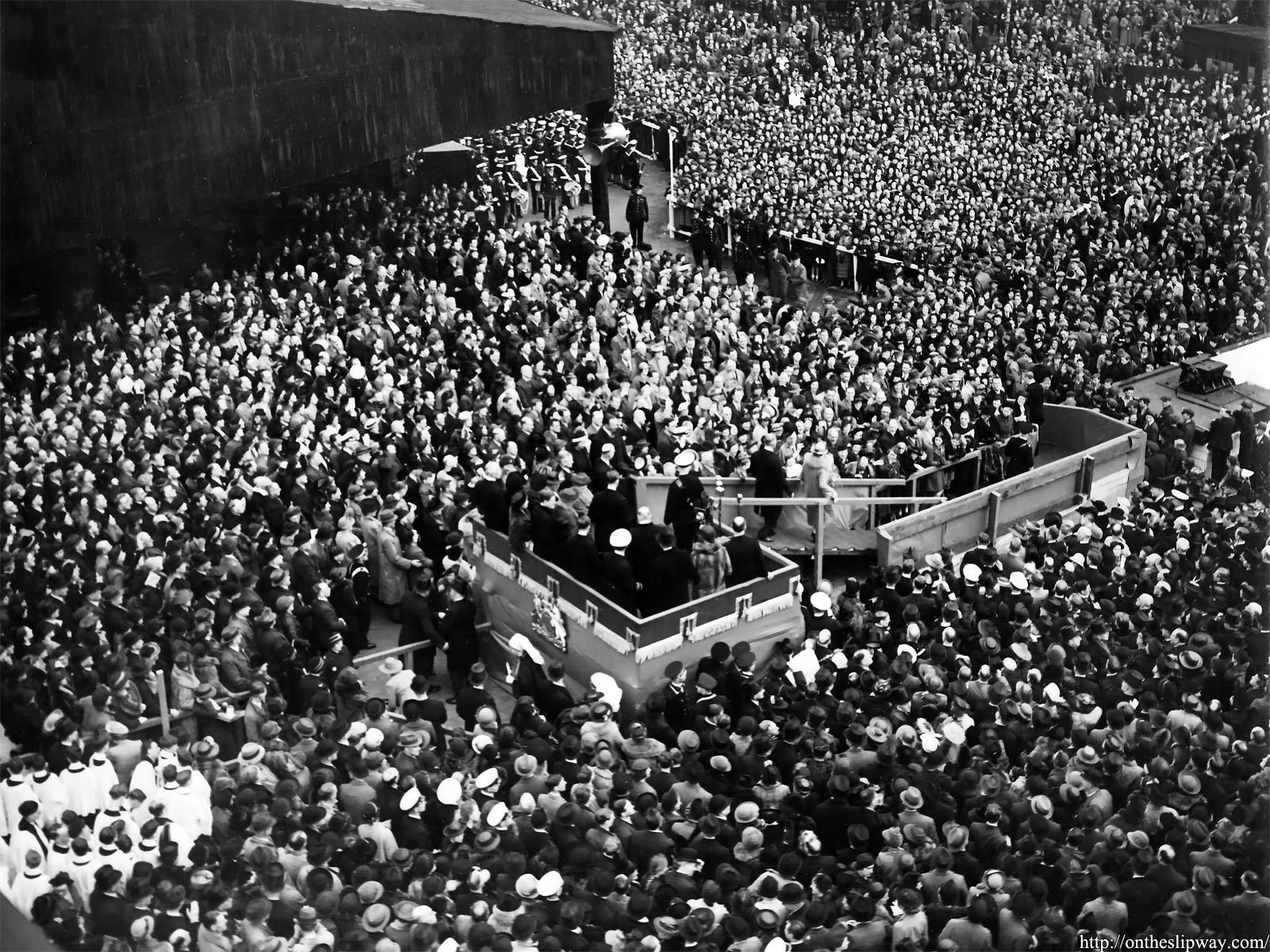
Note the many cameras in the background recording the launch.
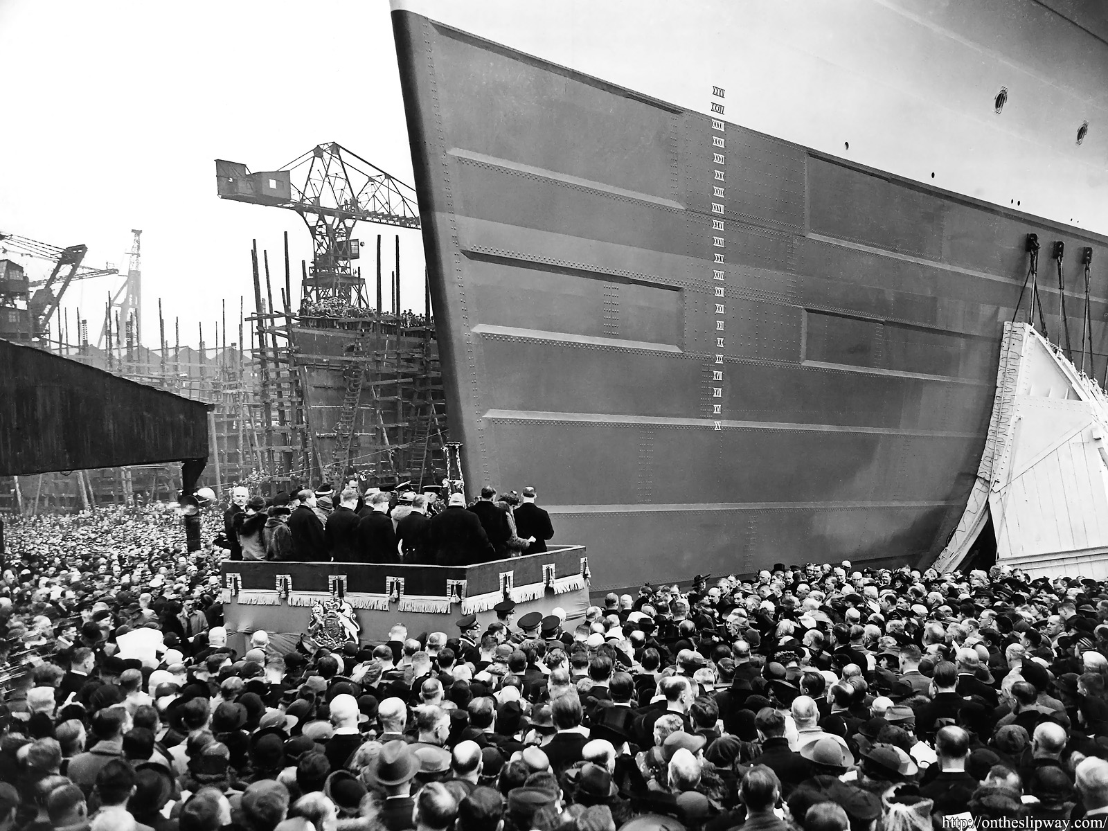
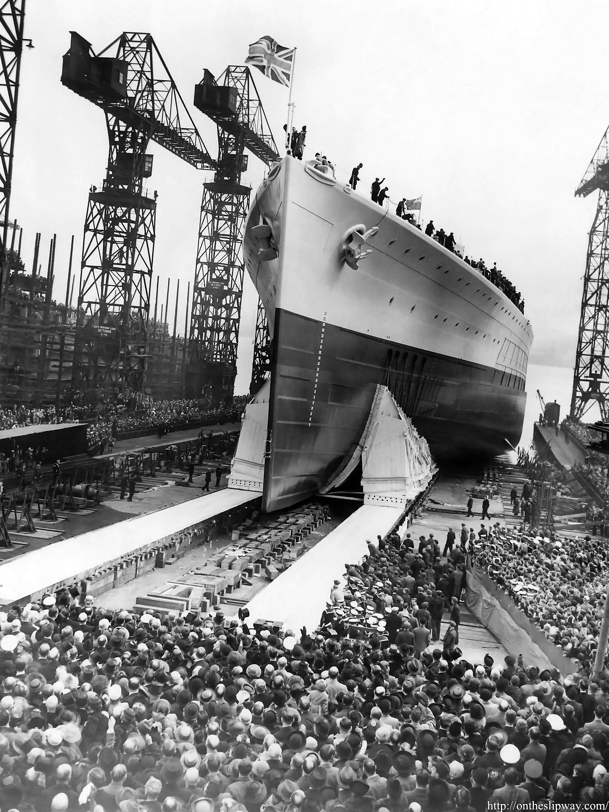
Although some welding was applied in HMS Prince of Wale’s hull construction, most of it was still riveted. The overlapping hull plates were caulked and then a sealing compound called Aranbee was added to vertical raised plate edges (roughly perpendicular to the flow direction), between butt ends, and, in the bow and stern region—outside the region of the main armoured belt—to all raised plate edges in steamwise direction, giving the hull a smooth appearance
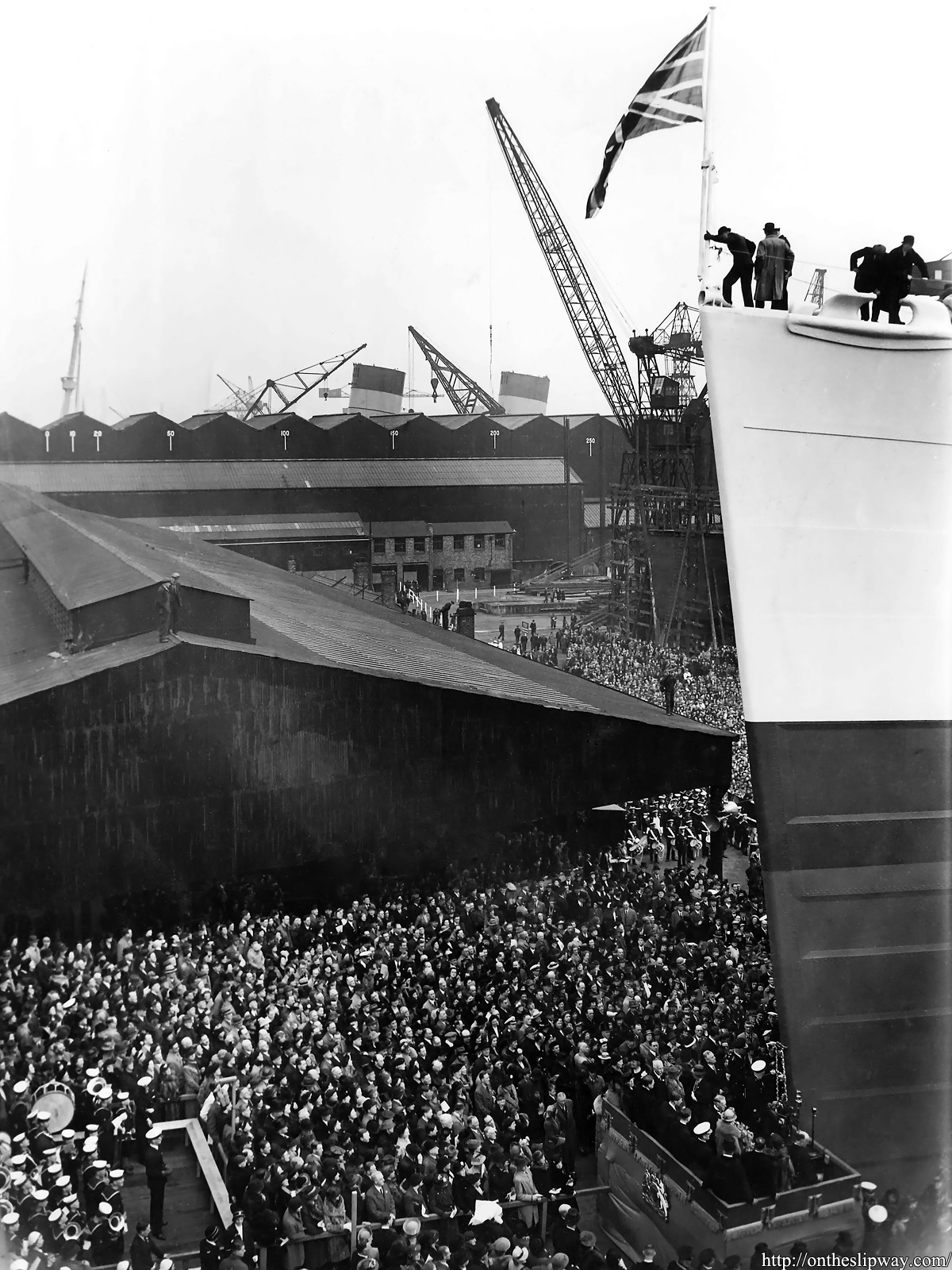
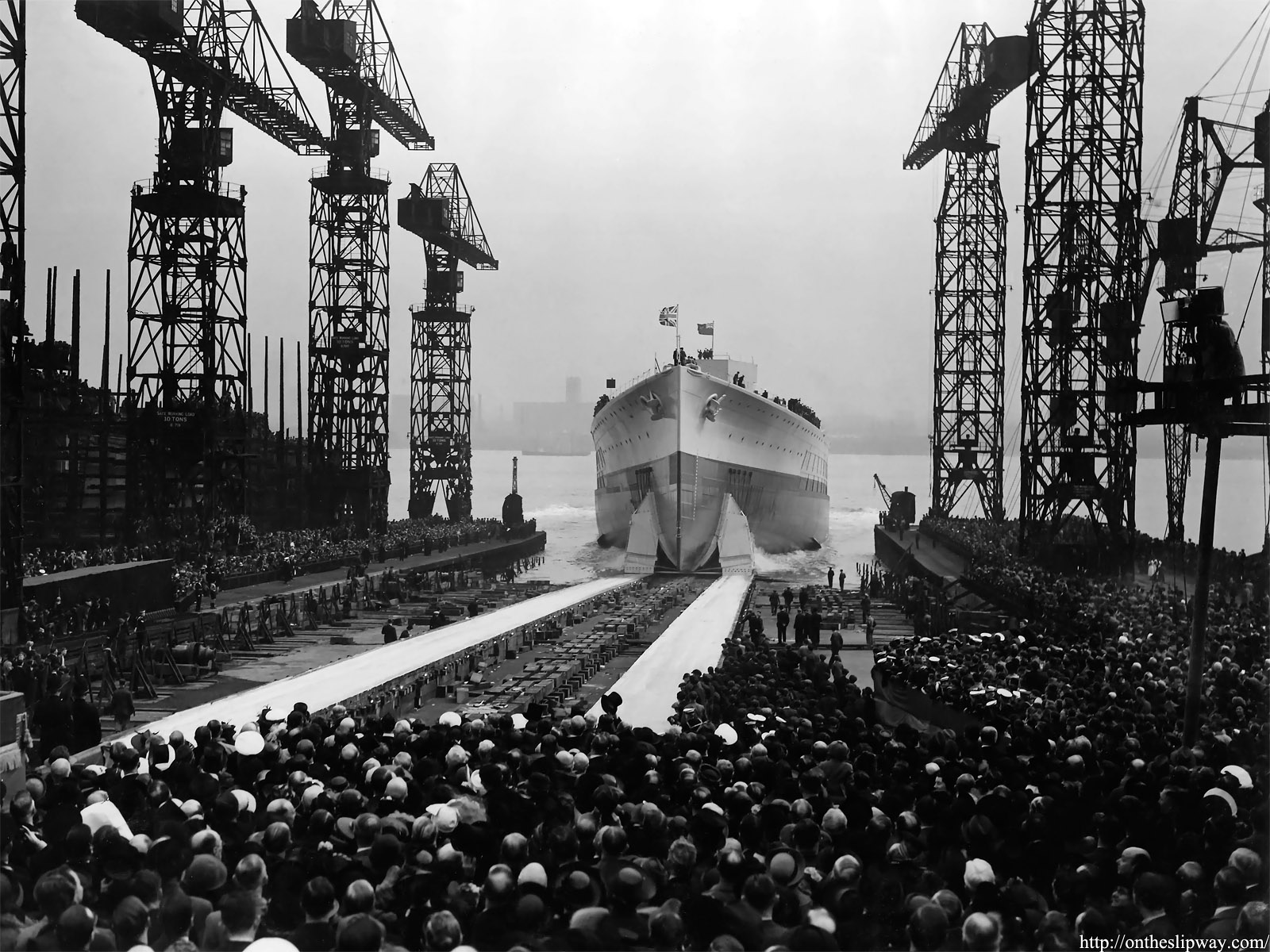
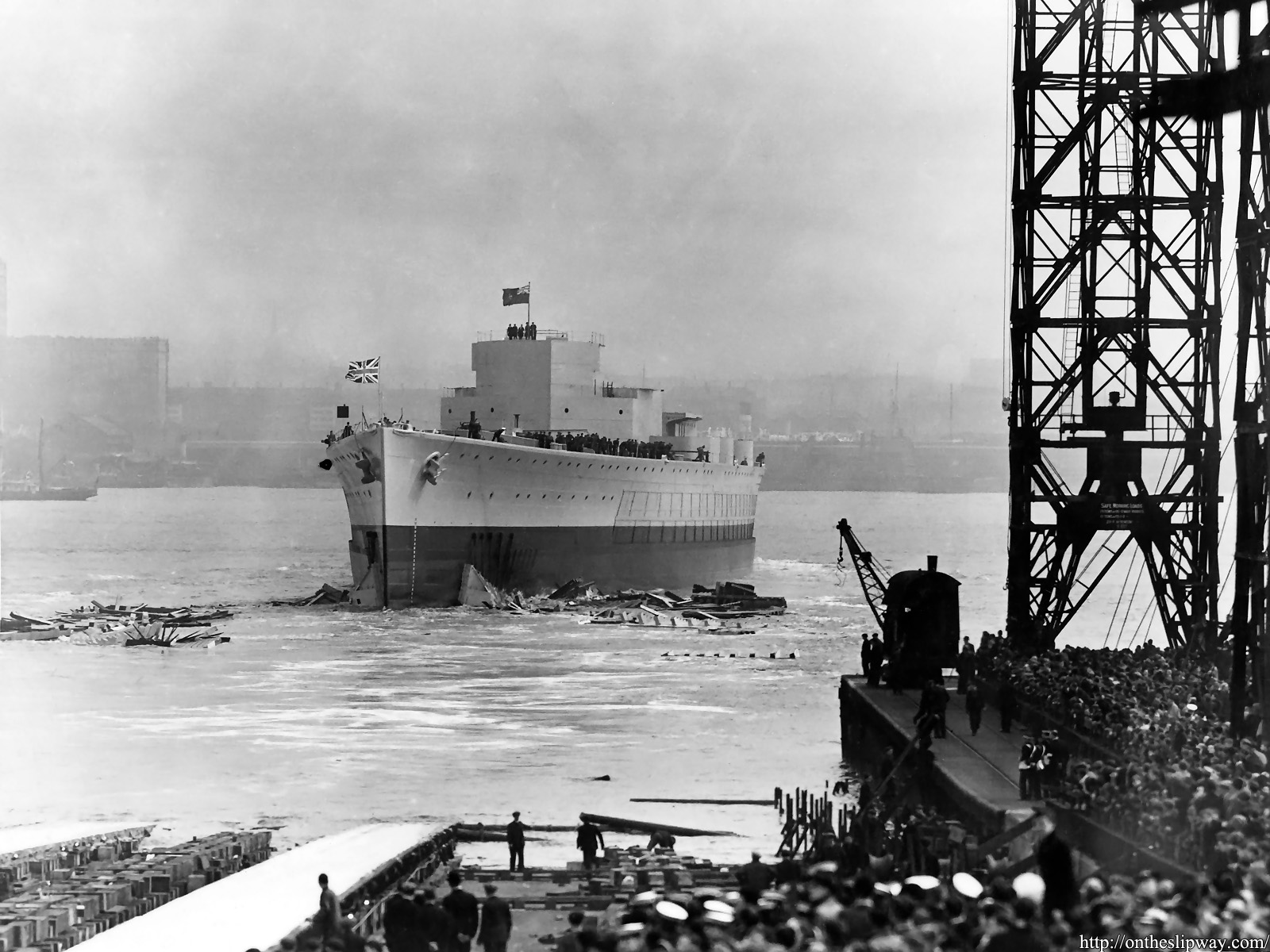
In the background the foremast and funnels of RMS Mauretania, launched a year earlier, are visible (not to be confused with RMS Mauretania from 1906).
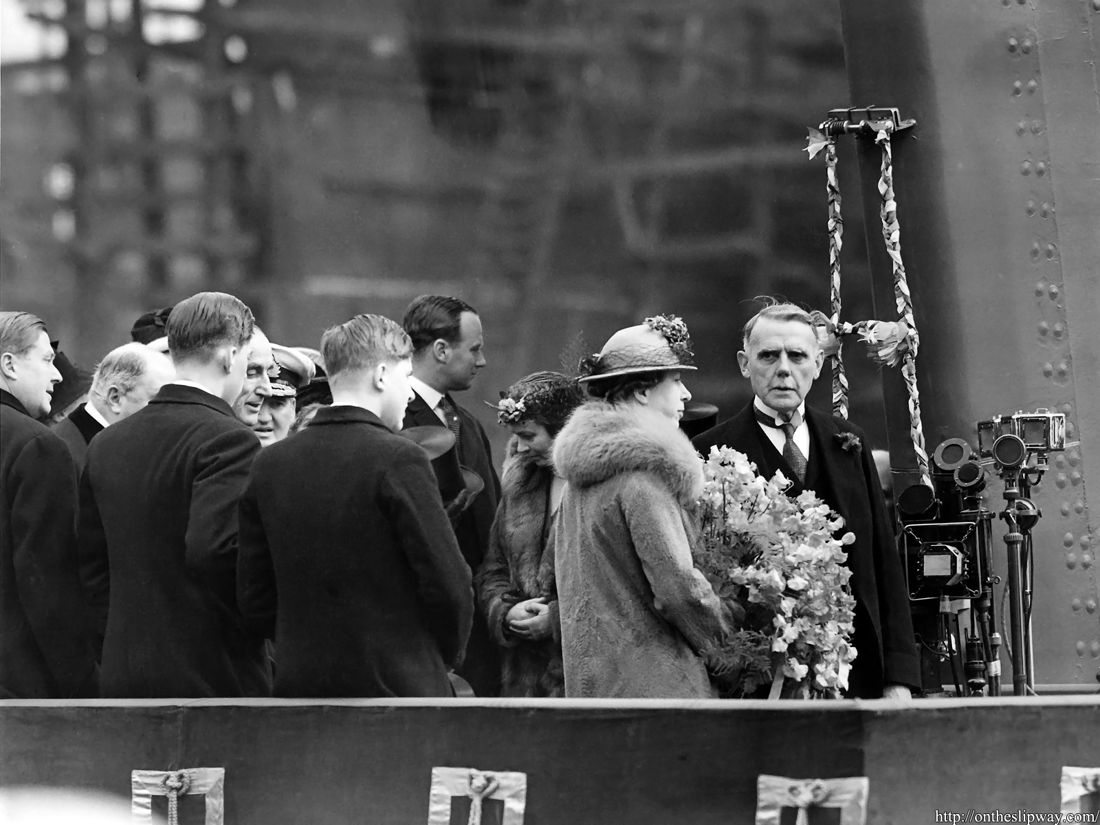
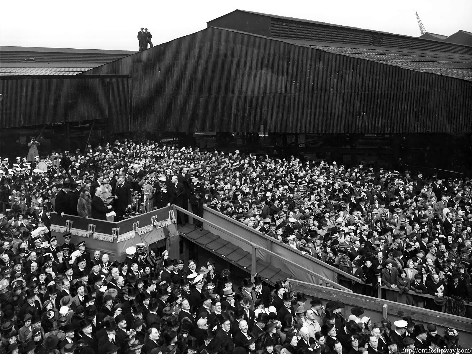
The Princess Royal prior to her commissioning speech.

(This particular image is from my private collection, not part of the Wirral Archive collection)


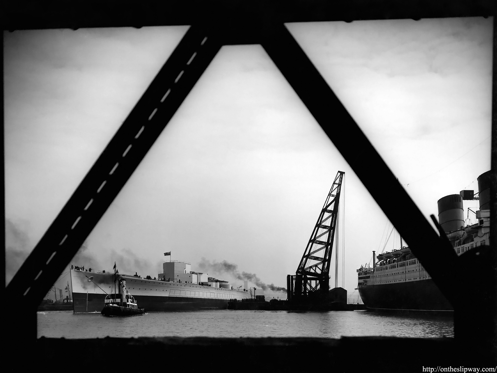
HMS Prince of Wales takes her place in Cammell Laird’s wet basin next to the RMS Mauretania.
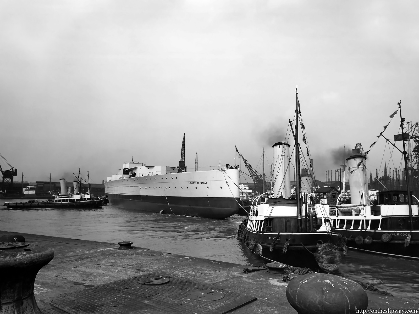
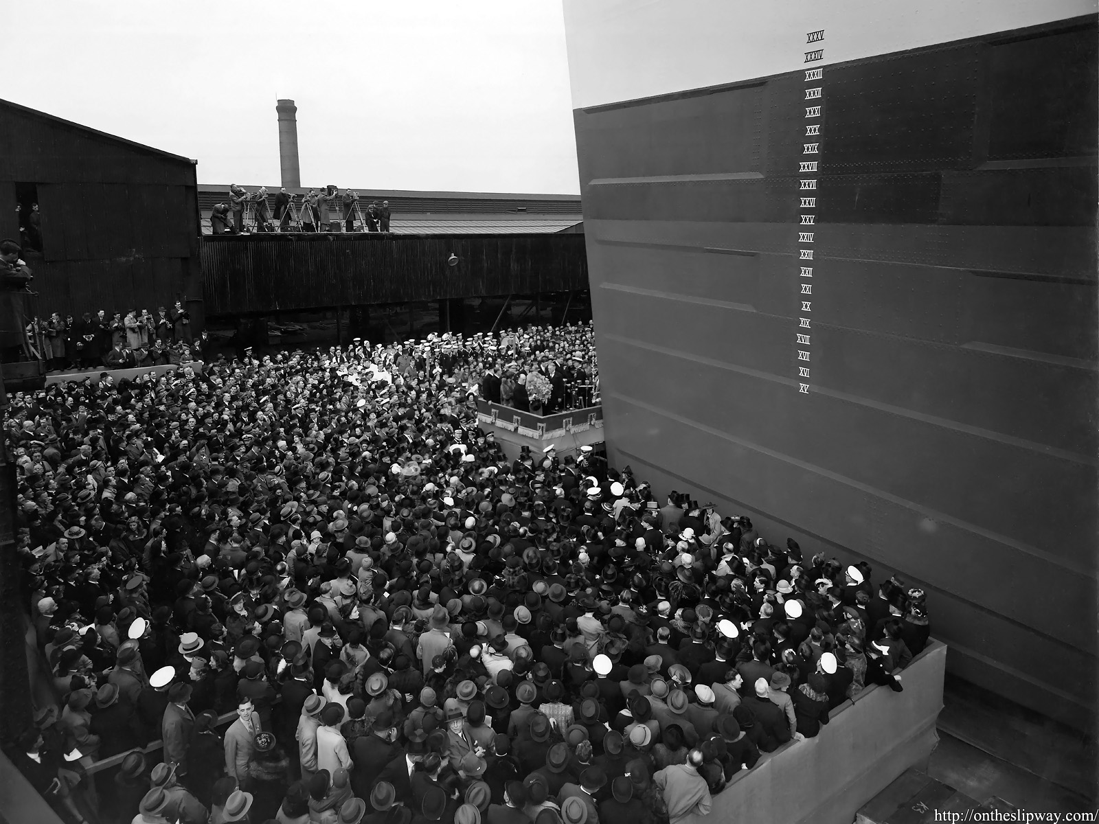
A particularly striking view. Note that the side armour has not yet been fitted.
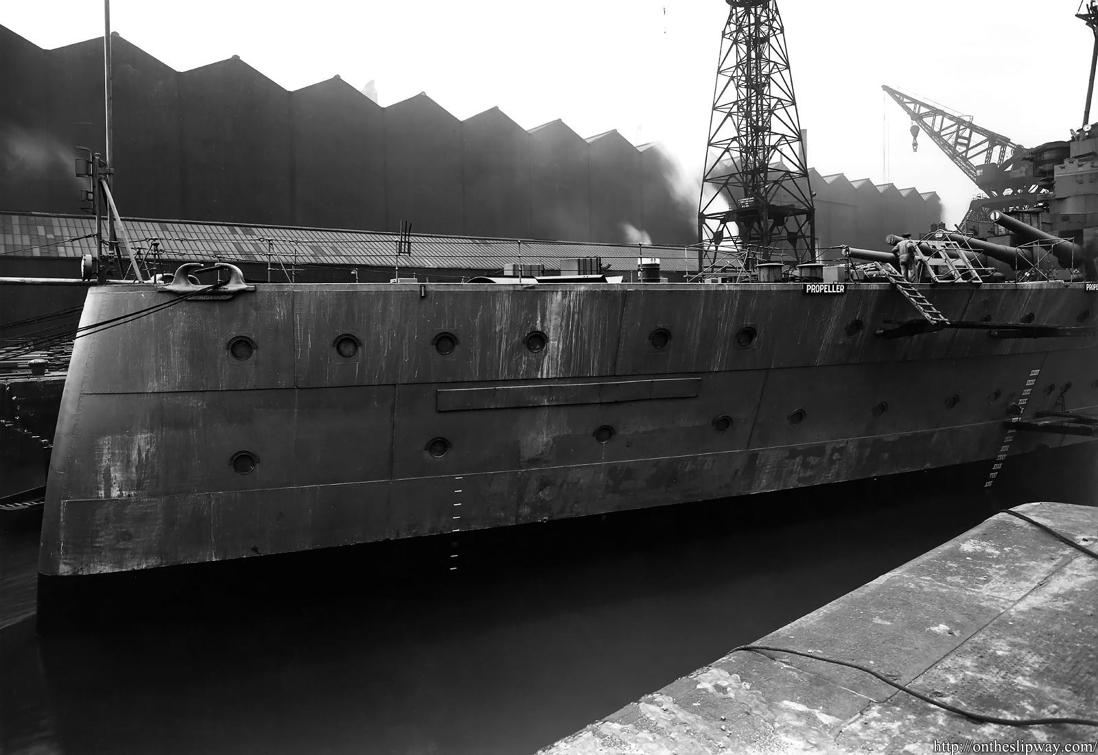
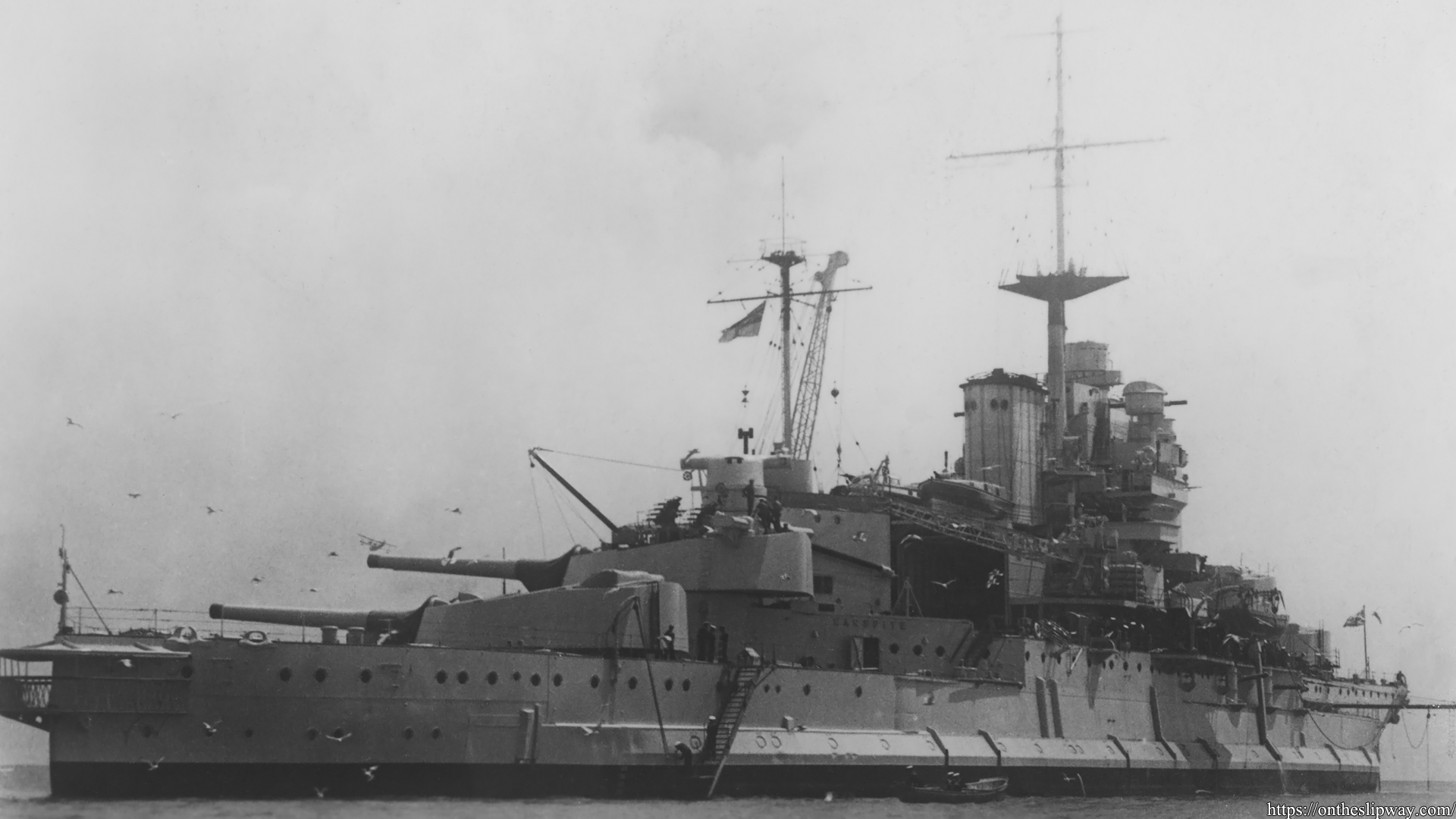
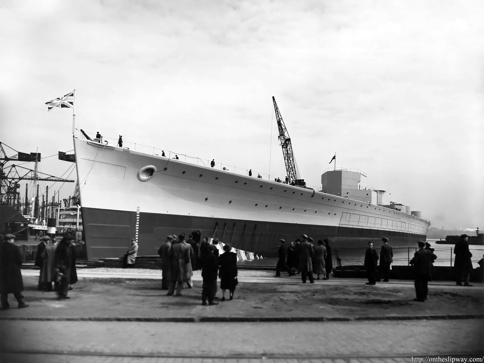
This collection contains only one well-known image of HMS Prince of Wales during her fitting-out. HMS King George V was the only of the class to have square scuttles at the Admiral’s dining and day cabin located in the stern. Although the scuttles here are clearly round, six rectangular cut-outs appear to be visible in the hull; the yard considered the square scuttles ‘incapable of watertightness‘. At right, next to the ladder, the storage rack for the night lifebuoy can be seen. This rack was removed before she sailed for her historic Atlantic Charter meeting.
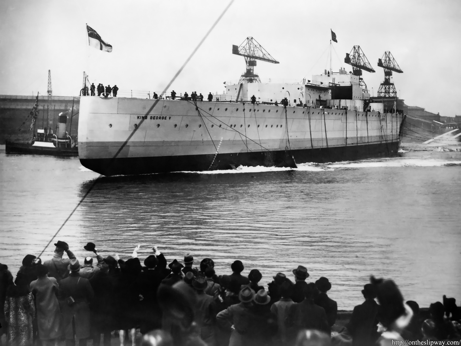
Thrown in for good measure; the launch of HMS King George V. Note: the scuttles of the Admiral’s dining and day cabin are not yet present.