Author: efoeth

Main Guns

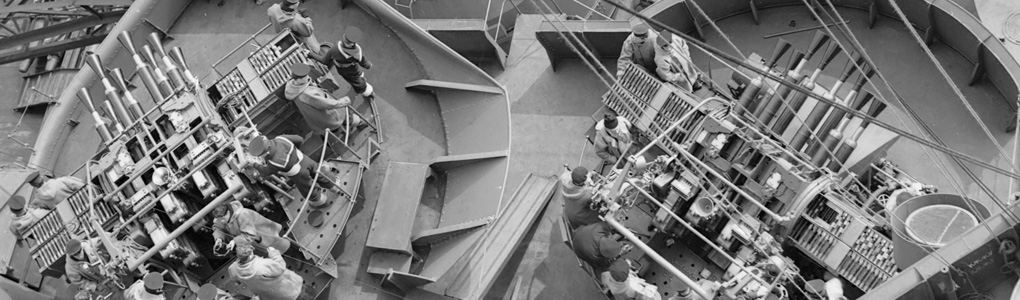
The turrets of HMS Hood are the second generation of 15″ turrets and only fitted to HMS Hood (The only ship with 15″ turrets after HMS Hood is HMS Vanguard, fitted with leftover material). The tricky part is that the bolts of the roof armor plating are very well visible while the older Mk I turrets are smooth. As I built these turrets a few years ago, I had some experience already with this difficult detail. So, when White Ensign Models asked me to build a set of replacement turrets for Trumpeter’s kit, I thought it would be a great idea.

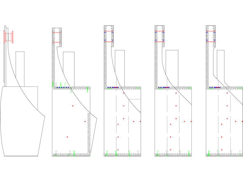
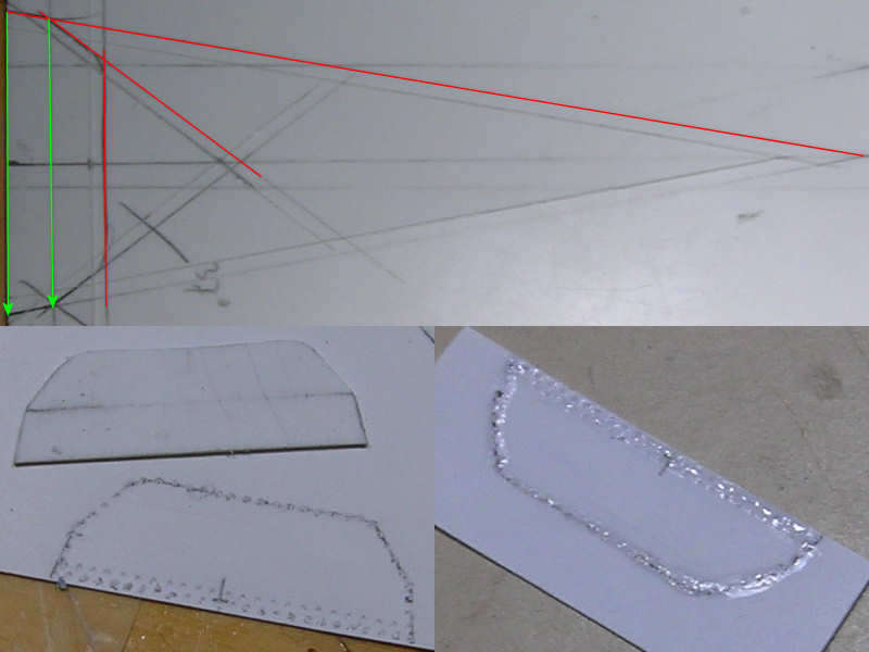
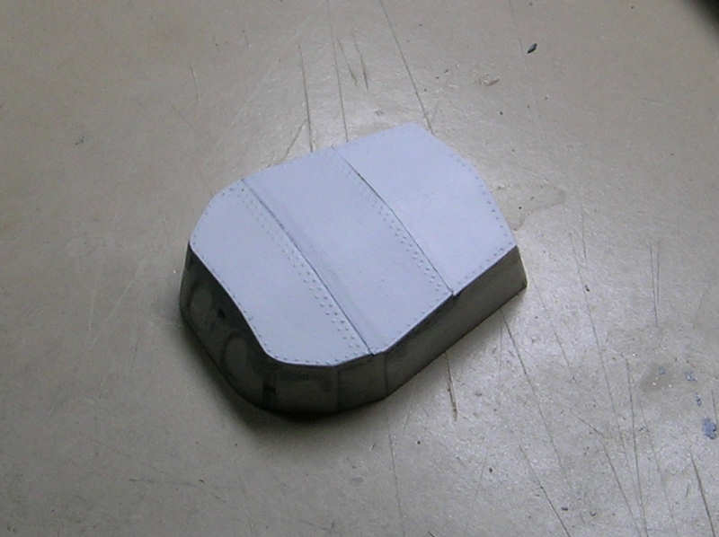
The turret doesn’t have a 90-degree angle anywhere, only a nice flat bottom to work from. I started by drawing it out.

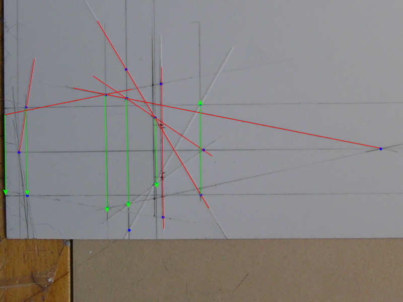
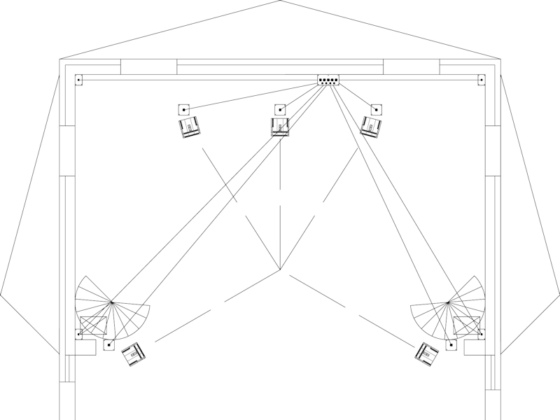
First, when you draw out a part and it has a few odd angles, it is worthwhile to draw a few additional lines as a framework. I drew a centerline and two parallel lines. Note that I draw the angled outlines of the turret much longer than necessary. You can use the intersection with the centerline and the parallel lines. I mirror these points on the opposite side for the other line and use these points for the other angled line. This makes cut (symmetric) lines at an angle much more accurate. It does depend a bit on how well you draw the first line, but on a large scale drawing you can repeat the exercise for measuring as well: extend an angled line and determine a few intersection points. Draw these on the styrene.

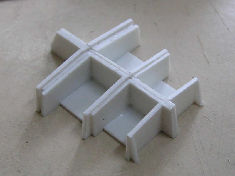
The backbone of the turret was added next. The roof of the turret consists on three large overlapping armor plates. The two forward plates are at a slight angle. As I intend to use 0.75mm plating, all dimensions are minus the plate thickness. Next to the backbones are the transverse supports cut to a 7-degree angle. Some of these plates double as a support for the side walls, but several additional side plating supports were added as well.

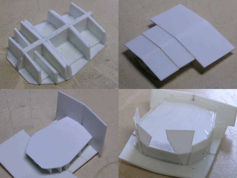
With all the supports in place, the roof plates can be added. These can all be trimmed to size later, after the sides are placed. The roof plates and turret rear plate are way oversize.

The front of the turret is a bit more tricky, as there are three viewing ports and I also wanted the outline of the barrel opening present. I’m not sure if Trumpeters parts will fit exactly, but I rather use the correct curvature of the turret than adapting the turret to a poor part. The shape was slightly lost with sanding…. I do hope it fits… Here you can see how I constructed the front of the turret.

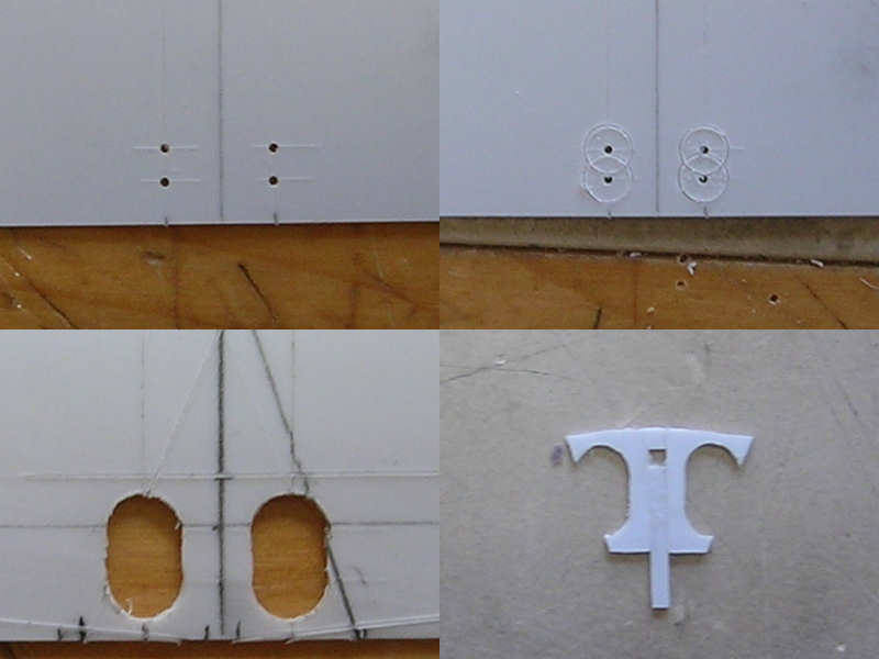
The roof itself is a bit of a nightmare. I need to have the bolts well visible, but gluing them one by one didn’t really appeal to me. I used a 0.13mm Evergeen plate, the thinnest I could find, and built a few templates with the exact shape of the turret roof. With some trial and error, I managed to draw a suitable bolt line. Next, -here comes the part you’ll really like- I drilled in each individual bolt. The drill damages the 0.13mm sheet, but in a way it looks really nice from the other side. I tried this technique a few years ago and couldn’t do it, but now I seem to have a steadier hand. I filled the holes with CA to avoid damage during handling later.

Now you “only” need to glue the plate to the roof top. You can use normal glue, but that will melt the 0.13mm plate. I thought I could avoid melting this time and used plastic glue anyway. After half an hour, a small spot was plainly visible on the roof plating! I had to do the plate again! And that plate wasn’t the first version I tried either… The latest bolted rooftop was held in place with tape and I carefully added glue under the roof plate with a strip dipped in CA. This finally worked! Unfortunately I made an error when adding the second roof plate and smashed the turret to pieces when I lost my temper. This normally doesn’t happen but I wanted to have the part finished in time. Well, these things happen! Back to square one…

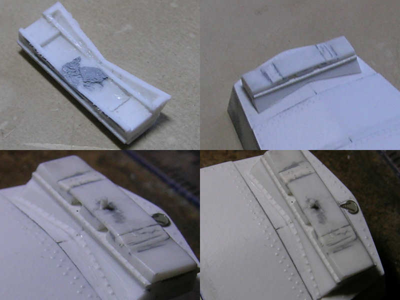
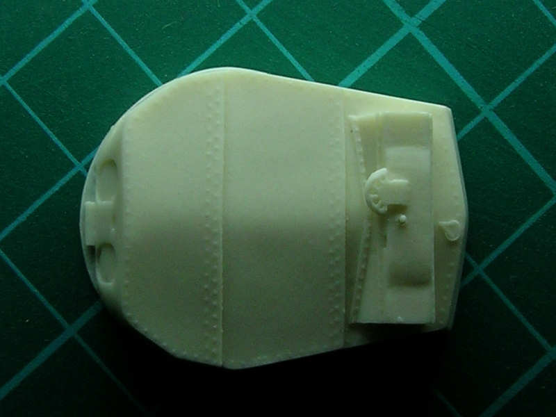
The rangefinder is a large cast metal object bolted in place. My previous turrets did not have these bolts but I really wanted them for the WEM set. This time I used a different technique that works quite well for straight lines of bolts. I used the gear from an antique clock, filed down the teeth and just let it roll along a ruler. Instant bolt heads! This is really a very easy thing to do and results in great subtle detail at zero cost.

The rangefinder has two openings on its front, one commanders view ports and the gun layers telescope. As this opening wasn’t documented very well and due to a lack of pics, I “forgot” to add it to my original turrets. The top of the rangefinder as a slight height increase at the center, sloping gradually at the sides. This slope was very tricky to do, as my filing skills aren’t on par with the average carpenter, so took a bit more time and effort.

A tricky part is the front of the rangefinder attaching the turret roof. It has a 45-degree slope, but connects to the roof plate that also 7-degree slope in the other direction. How to cut the V-notch out of the plate that will result in a perfect fit? Mathematics to the rescue! This angle can be easily shown to be equal to:

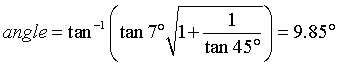
That just fits perfectly as you can see in the pic above. A strip with bolts was placed where it connects with the roof. I added a hatch from my own photo etch set to the rear of the turret.

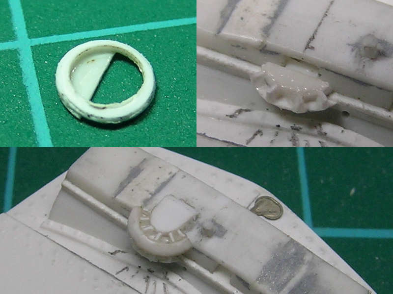
The commander’s position has a wind screen. This part should be hollow, but that would be a bit tricky to cast. I started with a styrene ring filed to shape and added the supports later.

The rangefinder itself has two distinct styles, as a change was implemented somewhere in 1939. I also thought it would be neat if you could choose between open and closed viewport, so eventually I ended up making eight parts.

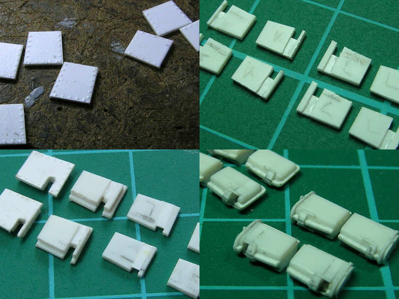
The top left image shows the center plate of the range finder arms with bolts in place. I made both top and bottom parts to shape and cut out the location of the viewport. I glued the bottom part first, so I could use it to file away some material from the bolted plate. A small strip is placed in the slot, giving a nice open appearance.

Here you can see the final part, fresh from the casters. Bolt detail is nicey retained and fortunately no marks or dents are present on the turret plate.

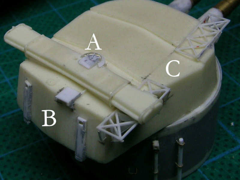
The first part to go from the resin copies is the wind shield, which is replaced (A). Now it’s actuall a wind shield kept in place by four supports. It was made by gluing 36 degree arcs and 2mm strip angled 45 degrees at the end to a strip. The shield itself is a ring cut to size. Vents are added to the rear of the turret, including a small platform (B). A small walkway is present to gain access from the aftermost twin 4″ gun position to the turret roof. At (C) the abandoned attempts of mounting an aircraft launching installation on ‘X’-turret. This frame initially consisted of 8 squares with a cross bond, but the two center squares were later removed. The remnants of the frame were present the rest of HMS Hood’s carreer. I haven’t seen this particular detail correct on any model.

Orion; the listening room

Meanwhile… we bought the house we currently live in because it allowed for expanding our living room. The audio setup was integrated into the design; I even gave the architect a CAD template with five loudspeakers called ‘the holy audio circle’ that was not to be changed. The audio was certainly not the main reason to expand the living room but it did play a very important role.

This is a view of the expansion; not your everyday house. The architect started with several form studies of which one (with side roofs) completely unlocked the solution to all our design troubles. We made a semi-rough outline of the design that we wanted with slanted side roofs, a suspended walkway and a mezzanine high up in the living room. The architect changed the sketch into a real design by removing all bad aspects and adding many a good idea; a spiral of creativity that was great experience.

The view of the living room shows the promiment position of the speakers and the subwoofers in opposite positions just below the stairs to the suspended walkway. The couch will have to be placed in the ‘sweet spot’. There are two cables running to the forward corners, just in case. Fortunately my wife fully agrees with me that it is all right to sacrifice an entire wall for the audio and home theater experience (choose your wife carefully before embarking on your audio hobby).

When are making such a drastic change to your living room there is an excellent opportunity to think about the wiring. Here you can see the tubes for the audio cabling in position just before placing the floor beams and insulating slabs.

The cat makes his round at the end of each working day, inspecting what has changed. In this case, a new floor with audio tubes clearly visible. The very large tubes on either side of the concrete are for the rainwater discharge. The audio tubes near the (still) existing wall are not in their correct position, but the contractor thought it would be easy to pick them up later. The wall was knocked out; the old floor was completely removed and replaced by more beams and insulation.

The inner walls and roof were all prepared in the factory and the house grew rapidly. This is a subwoofer cable tube exiting among the highest concentration of electricity lines; I tried to avoid any 230 Volt lines running near speaker cables, let alone parallel to them. This proved to be harmless.

This is a nice view from the suspended walkway and the mezzanine. There’s no boxed-shaped listening room here! The distance from the mezzanine to ground level is 4m / 12 ft. The mezzanine is used often as a table top gaming platform.

The outside is pretty spectacular…

A second layer of concrete was added; blocks of foam where placed near the audio tubes to create ‘audio pits’ (top: main connection, bottom, rear left and left sub + socket on the audio group). I hammered wooden frames to later hold the hatches in the floor during the weekend. The cables have already been pulled though the tubes by the electricians.

Even though we enjoy laying floors, we did not lay our own as we had no experience with gluing and didn’t feel like experimenting (we’ve been in a mess for half a year; it tends to get on your nerves and depletes your resilience for small setbacks). You can see wooden hatches in the audio pits at the right side of the image. I made these hatches from a few spare floor boards. When I took this image I actually just removed one of the boards with a crowbar. The position of the hatches was carefully specified but they miscounted by one board. Still, I could clearly see the difference between my attempts and a professional at work and my wish (demand, actually) to have the center board run exactly through the center of the living room was very well met. The pits were designed to absorb an error of half a board width, but still….

After the construction company left it was my turn to fix the plaster, paint the walls, place wall sockets and solder the speaker cables. I added some hose clamps to the speaker tubes to avoid them getting lost forever below the floor. This is the main connection board that connects to the audio gear. Needless to say, there is now only one place in the living room where I can stack the amplifiers.

Subproject complete!

NEXT

Introduction
The plan
Design changes
Signal processing
The listening room
Production
Listening

Orion; design changes

The cabinet of the Orion is not so complicated and actually is less demanding than a boxed loudspeaker; the general shape just needs to be correct. I needed to deviate (slightly) from the plans to change the appearance to straight lines as my wife really doesn’t like curves on her speakers (no KEF or B&W for me). I decided to build all the individual panels with interlocking box joints as I like the appearance of these joints showing the structure of the wood and variation in colour. However, the box joints do introduce risks; the work to make each panel increases dramatically and inaccurate work may result in panels that no longer interlock nicely. This is exactly what happened, but the result isn’t too bad for a first attempt.

Making the box joints would be most difficult if it weren’t for a Festool jointing system: box joints made easy. You clamp the panels in the jointing system, place a guiding template and just let the router follow the guide. Naturally, I should say box joints made comparatively easy as I really had a lot of trouble making proper joints at first even after thoroughly reading several how-to’s available on the Festool site. Using the router properly is a challenge by itself. You really have to mill in the right direction or the bit will act as a wheel and propel the router forward. If the lateral movement isn’t restricted by using guides or router slides, the router ends up where it’s not supposed to go. Before you know it, you ruin a work piece. I spent many hours practising and making router shapes trying to master the router. This mastering process is far from over though I’m getting less scared of using it. The number one rule when using the jointing system is: no not lift the router while routing. I did this once damaging a template, the work piece and my self-confidence. The normal procedure for making the box joint is clamping both ends of the two to-be-joined workpieces in the jointing system so that they will fit nicely. I milled all the parts separately so that it became important to start a joint at the correct position. I didn’t think of it until later, but I should really have made some guide blocks to have accurate and repeatable positions to work with.

The panels were always clamped strongly between two strips of MDF to avoid splintering when the routing bit enters or exits the panel; this reduced the splintering drastically, although damage remains visible on the cabinets when the natural structure of the wood couldn’t take the stress from the routing.

As I used the Festool jointing system the dimensions of the Orion Cabinet had to be changed to whole centimeters; the router bit is 10.0mm and the box joint step size is 20.0mm. The panel thickness was reduced to 20 mm. The goals for the redesign of the cabinet were simple:

1) No external wiring visible except from the cabinet directly to the drivers. One of the disadvantages of an open baffle loudspeaker like Orion is that you can see the wiring all too clearly which I do not like. When a slot is routed in both box joints of two panels, a small channel is created that can house the wire. Of course, a total four wire pairs need to be hidden.

2) Reduce the chances of failure of a part during manufacturing. This sounds straightforward enough but I started this project without any experience in wood working. I knew from my other hobbies that trial and error is required before you obtain an acceptable result. By practising with the router, I reduced the changes for failure slightly, but not enough. I also knew that I needed to be very careful when cutting the longer panels to length and that I do not have the tools at home to do this. The side panel of the Orion had to be split; the jointing system simply isn’t long enough.

3) No or as little visible screws as possible. The early designs leaned heavily on screws and these were all placed in inconspicuous places or covered by other panels. As the box joints themselves proved nearly strong enough to keep the entire speaker together I used glue almost exclusively so the screw headache was no longer present.

4) Ease of assembly. I spent a lot of time figuring out the correct build order and how to connect what to what. In the end the screwless design resulted in a very simple assembly order and this became less important.

I went to work with these items in mind. Move a panel a bit left or right, reposition a screw, change the joints from odd-even to even-odd between panels, etcetera. Perhaps I overdid the planning phase but I find the result simple and elegant, not showing traces of all the worrying that went before it. The above shows the original Orion profile at left and some of the slight changes evolving into the final variant. The baffle for the midrange was positioned a bit forward to be flush with the woofer cabinet, changed into the dimensions recommended in the plan set when you do not use the curved outline.

NEXT

Introduction
The plan
Design changes
Signal processing
The listening room
Production
Listening

Orion; production

I decided to make the speakers from American Walnut bought in the wood harbours of Amsterdam. It’s very expensive to have rough timber cut the panels of an exact size so I learned how to work with the overhand planer (surfacer) and the thicknesser (vandiktebank) at work. I made strips of 90 and 110 mm wide, glued them together and cut them to the correct thickness. I spent nearly three days in the woodworking workshop explaining the high price of custom-made panels admirably.

I had a few templates made by a CNC router from waterproof MDF, including templates for the floor hatches. The template at the far left is a bit smaller than the panel next to it; this was an error of the milling company but it worked just as well.

I do not have a nice workplace so I worked outside. I just clamp down a panel and start sawing and milling away with the router.

The panels weren’t sawed but milled to size with a template. Not overly accurate perhaps, but a good alternative to not having a decent table saw. Note the damage for this board that fortunately fell in a driver position. I’ll have to pay more attention when buying wood next time; this panel was too thin and couldn’t have possibly been suited for a decent panel.

This is one of the smaller cover plates of the woofer cabinet with a channel for the wiring already in place. This channel should have been routed after producing the box joints and assembling the woofer cabinet; lots of the box joint ‘teeth’ broke off during handling and fitting. For the midrange baffle you have no choice, the channel cannot be routed afterwards.

I also had to learn the hard way that when routing a circle that it’s best to use a jigsaw to remove most material and use the router to finish the circle off. If not, the disk being routed out of a panel separates from the panel and can bounce violently against the still routing router and panel. This destroyed one beautiful baffle. I also tried to route a wire channel through the side of this particular panel, leaving box joints 5mm thick and that didn’t work (1 panel ruined). I also changed the direction of the grain of the wood for the woofer cabinet cover plates (1 panel ruined). With all the practising, failed attempts and rejected panels I ruined enough wood for one additional Orion cabinet. Oh well, it’s a hobby.

The first parts were glued using a disproportionate amount of clamps. I used some random wooden strips to distribute the load and avoid the clamps damaging the speakers. Before you start gluing it is best that you keep filing away at the joints until the panels no longer require force to make a good dry fit. A proper dry fit will also ensure you’ll have the ingredients to quickly assemble the parts when gluing. I started differently and some of the joints, particularly for the front panel with the wire channel, bent a bit during assembly leaving an ugly pattern. I also learned too late that after the glue had dried (I wait for about three hours) you need to rinse the speaker and remove as much of the excess glue as possible (some say scrape excess glue, water may make the surface uneven). In any case, when you wait too long you can only sand the excess glue off and when the box joint isn’t flush you need to chisel it out between the recessed joints; not nice. Some of these beginner mistakes are still visible on the earlier-assembled parts.

This is the support for the magnet mounting of the midrange driver. I used a rampa screw and M5 threaded wire to mount the driver, removing the screw that normally holds the midrange driver together. The wiring runs through the support and through the top plate of the woofer cabinet. I actually needed to practise drilling a hole that long. Drilling the final parts when I didn’t have enough panels left for a replacement was the most anxious moment of the build.

Here you can see the wiring of the tweeter and the midrange running behind a box joint; the row of box joints of the upper and lower side panel are only half as thickness of the panel. I carved a channel from the top plate of the woofer cabinet to the center panel.

The two cables from the midrange baffle are joined by the two woofer cables. I later added the large recess to hold the cables in this folded position. Having a bit of extra length helped during assembly and should I have to resolder a connection I can at least remove the Speakon connector from the speaker. This was a very last-minute addition that was very convenient for the build.

A scary moment; the final panel is in place, covering up all the cables with no more room for repairs.

Here you can see the midrange driver without the phase plug. I started with the phase plug forcing the driver to its mounting but I later placed 15 washers and a hex nut. The phase plug is now screwed on with less force.

The cover of the midrange driver is still present. I cut out an opening and placed a few washers; the mounting is quite rigidly forced against its support. I hope the connection is strong enough or I’ll have to drill out the support and fix another nut & washer to the rear; now it’s a nice blind connection.

The Speakon connector fits in its own box-joint block. It’s a nice addition that was much easier to draw than to make!

Subproject complete!

NEXT

Introduction
The plan
Design changes
Signal processing
The listening room
Production
Listening

Copyright © 2026 On The Slipway

Theme by Anders NorenUp ↑