Category: General

Vents II

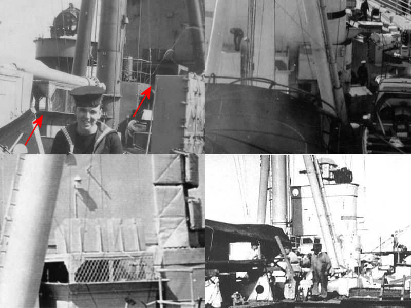
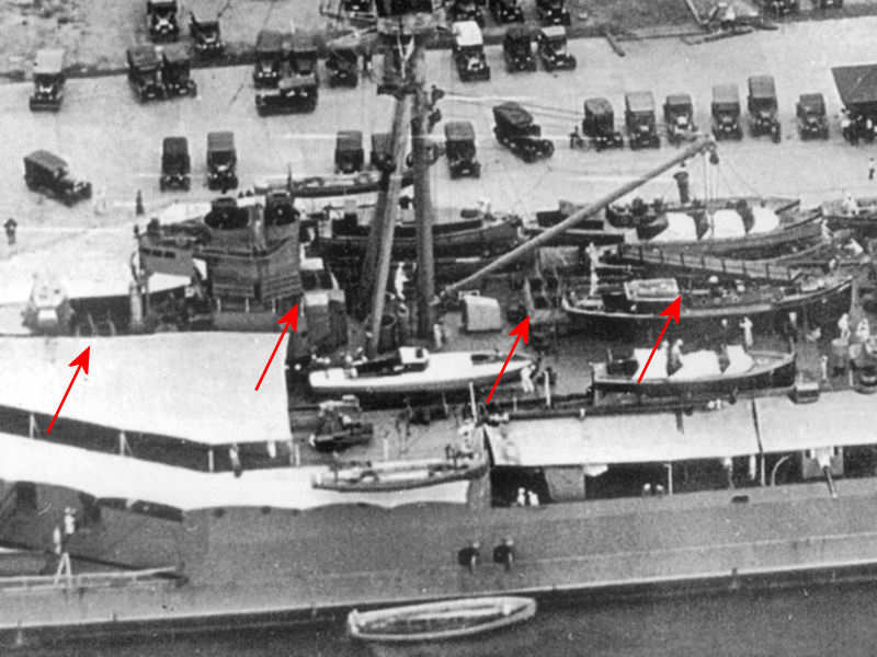
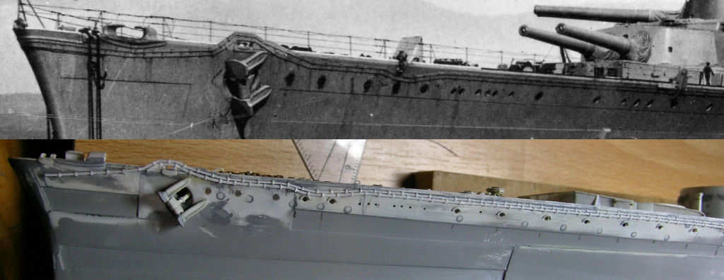
For some reason I avoided beginning to build all the mushroom vents of HMS Hood. There are many sizes and shapes and they are both numerous and small. I took the basic measurements from “Anatomy of the Ship: HMS Hood”, drawing I1: Fittings. I brought the total number of different mushroom vents down to about four and tried to classify all mushroom vents on the drawings and photographs. I decided on Large  (2.4mm or 0.095″), Medium Large (2.0mm or 0.08″), Medium Small (1.22mm or 0.048″, a US punch size), and Small (0.8mm or 0.0315″). I tried to do a head count and came up with 13 large, 18 medium large, 32 medium small, and 31 small; 94 vents in total. As these parts are small I might loose them during handling and as I probably missed a few on the drawings or pictures, I had to make a nice supply of parts.

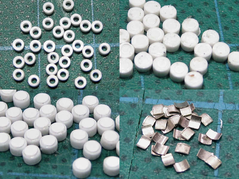
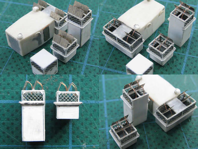
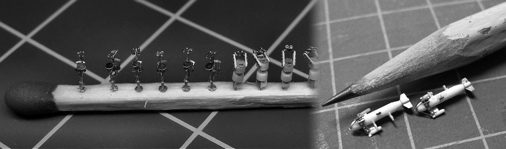
The largest vents are visible here, cut from tube. I added a disk to all rings so that the support of all mushroom vents has the same height; I now need to cut the support to length on the model, paint it, and then add the mushroom vent. This way I know what the height will be before painting the entire ship and I do not have to get the height correct of each vent to what is visible on the photographs after painting . After this disk was placed, a small disk was glued on top of the vent as detail. None of the vents on the photographs have any more detail such as a hand wheel. Too bad, would have looked nice.  The grille of the vent is simulated by an etched part bent into shape and set with superglue. I only had tubes for the largest vents, the two medium sized vents were made from rod with the center punched out as explained here. This was some work with many casualties due to off-center punching, dropping to the floor, misalignment and more dropping to the floor.

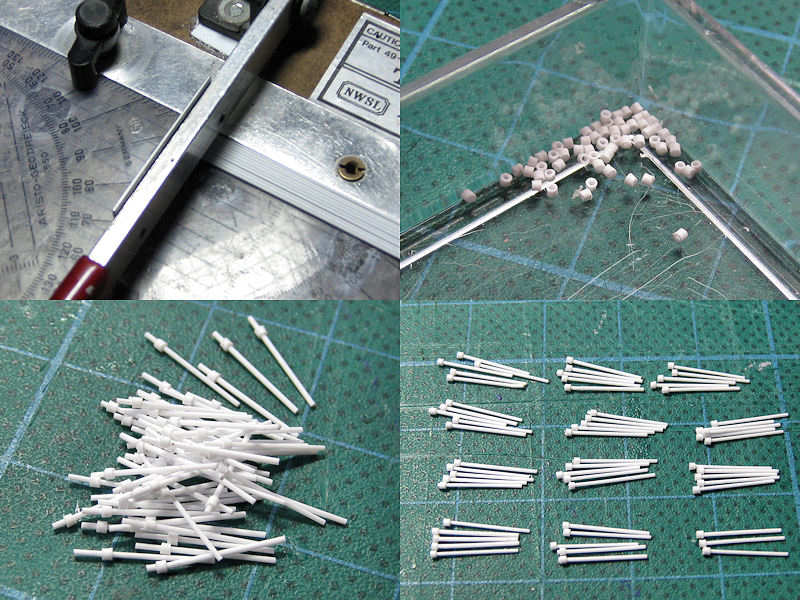
I started with the largest vents which I found to be small to begin with, and worked my way down. The smallest vents were really a challenge. I started by cutting up rod in batches of ten. They had their centers punched out by the ten-fold. I decided the smallest vents can probably be put into place prior to painting with little risk showing their white undersides or can be placed on the painted model. So, I put the rod in place. I first slid the rod in (bottom left), dipped the tip into superglue and slid the ring into place. The bottom right shows the result prior to sanding.

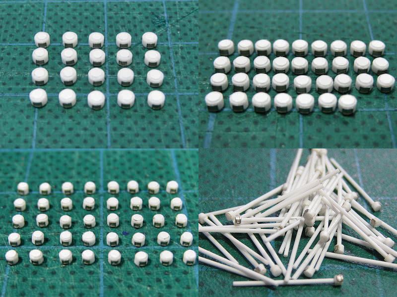
These are all the vents; 20 large, 34 medium large, 40 medium small and 58 small, 152 total. At least, 152 are left and dozens more are scattered around in the hobby room. Perhaps casting a few would have been possible, but I didn’t look forward to the prospect of casting several batches of tiny parts with a high failure rate.

Vents, part I

A series of boiler room vents runs through the bridge superstructure and next to the funnels. On all the drawings, two boiler room vents are drawn at the bridge location, but only one of them visibly exist the superstructure on the admiral’s signal platform. So, where does the other one end up? The top left section of the image shows the rear of HMS Hood’s superstructure, with the arrow indicating the exact location of the after boiler room vent. The other vent is seen on the image section next to it. The top right image shows the implementation on the model. I’m not exactly sure if the aft vent is correct, but this is all the material I have. The bottom half shows both vents in detail. The vents on the admiral’s signal platform intersect the base of the 5.5″ rangefinder towers.

There are four large engine room vents on the boat deck, all situated on the center line of the ship. The top left image shows a sailer posing with one of these vents in the background. A little to his right, the vent near the searchlight platform is visible. Notice anything? This vent is considerably taller than the other vent, which is not indicated on any drawing of HMS Hood. The other pics show the same vent in detail. It’s very easy to overlook the height of this vent, until you actively gauge its height from nearby details. It’s nearly twice the height of the sailer standing in the top right image. The top left image shows that a series of hatches are present on the top of the vent, including a small ridge around it.

This image has the location of the vents indicated. Notice that all hatches on top of the vents are opened toward the stern of the ship. It’s difficult to make out the outer right vent and I can’t tell if hatches are present. Probably not, as the main derrick is stored on a crutch on top of this vent, blocking the hatches from opening. The vent near the disinfector house (second from the right) is also blocked by the main derrick, but is built wider with hatches capable of opening when the main derrick is stored. This might be true for the vent at right as well, but I cannot find any picture showing this, with all the boats and launches stored there blocking the view. If hatches are present, I’ll add them afterwards as I’ll have the main derrick in the stored position on the model.

Here are the vent models that took a surprising amount of time to complete. I started by cutting strip to size, added wire mesh, cut the strip to height and width, and glued them to a rectangular base. A small 0.25mm strip was glued to each corner. The roofs are frameworks of 0.25mm strip as well. Small triangles were added to the corners of the mesh (difficult to do) and custom-etched hatches were added later. The hatches are fixed using arced supports, visible when stored in the top left of the previous image (behind the sailor).

Sounding Machine

A sounding machine is a device for (as far as I know) measuring the water depth. I wouldn’t have noticed it if it weren’t for these two photographs (from the HMS Hood site). . The “Anatomy of the ship: the flower-class corvette Agassiz” has an excellent drawing of the Kelvin Sounding Device Mk Iv on page 16, but it’s a different type. Good enough for basic dimensions and for some detail.

Fortunately, around the time Hood was built, several of the Imperial Japanese Navy ships were built in Britain and carried the same equipment. The photograph at left was found on the net, taken in a Japanese museum. The picture at right is from the book “Grand Prix Shuppan: Anatomy of Japanese Battleships 2”. From these two images I made a small photo etch design in Autocad.

At left, the photoetch parts are shown. I added some disks to simulate the detail prior to cutting the parts loose, making it easier to handle them. The lower picture shows the finished parts. Cute! The picture at right indicates where the sounding devices where fitted to HMS Hood’s bridge structure. That is, if they were still fitted in 1941?

Degaussing Cable

The degaussing cable proved to be a rather labour-intensive piece of detail. As you need over 2 meters for such a large model, you need a quick way to produce a lot of it fast. The cable was added to the etch set, but I wasn’t happy about the result at all. Also, from photographs of the ship, it is apparent that the cable was added sloppily, not at all as a straight and neat cable. So, scratchbuilding then!

I needed strip, a lot of strip, and with a consistent thickness. So, a short exercise in cutting lots of strip.

I start with some Evergreen strips with a smaller strip glued on to it (left). This smaller strip has the correct thickness for the to-be-cut strips. I put it to the plastic sheet (center) and then align the ruler (right). This gives you a pretty consistent strip thickness. I could have bought readily-available pre-cut strip, that is, if it were readily available and it isn’t.

This is the gluing jig. Lots of plastic strip to help me with aligning all the parts for the cable.

Here ten new strips of degaussing cable are taped to the jig.

And here are, err, lots of smaller strips taped to the mould as well. They have already been glued. I tried a few types of glue, some gave a very brittle bond.

The smaller strips were made from 0.13mm Evergreen sheet, that is, very very thin. I marked the sheet with a red marker before cutting, so I knew which side should have been up. I also added the line to the other side, so that you can avoid glueing the strip without it being rotated along its longitudinal axis. Pretty difficult to see if lt goes well with all these strips so a bit of color helps.

Once all the strips are glued in place, I cut the main parts loose.

I used two tweezers to fold all the small strips: one for holding it at the junction, the other for folding. At this point, I started to loose a lot of strips (breaking or coming loose). Next, the excess strip was trimmed by pressing it down with a ruler just at the junction and then giving it a quick cut with a new and sharp blade.

Then it was sanded down and repaired when necessary. If the reparation was too much work, I just cut out a section.

Before adding the degaussing cable to the model, I first had to add a small ridge on the exact side of the deck. These parts were very helpful in clamping a strip at that exact edge before fixing it with glue.

Hmm, that looks like the real thing, much better than etched cable to my surprise. Note how sloppy the real cable is and that the upper cable is slightly thinner than the other. And please don’t note that the portholes aren’t really where they should be. I’m not going to fix that…

I only had 7 sets to build, so doing it while being drunk alleviates the effort. I had all the cable I needed, but left one set on the table and I have cats. Guess what happened? I’d never thought they would do that…

Copyright © 2024 On The Slipway

Theme by Anders NorenUp ↑