Category: General

Searchlights, part II

The Searchlight part I post showed how the searchlight frame was made including the design for the etched parts. The design is repeated here:

The lantern is mostly made up from etched parts with one large to-be-rolled strip and some additional detail parts.

The rolling took some testing (made a few test lanterns first), but worked out well in the end. A stepped end cap was made with the lathe later sanded down to give the lantern its curved back.

The top detail has a small positioning block for the exact positioning (see top image, center, repeated on the rear surface of the detail part), the side parts are aligned on the lantern’s inclination axis. A small jig was made to hold the lantern in place while gluing the front detail into position.

The parts on the side really add a lot of wonderful detail. The parts were first rolled into shape and then added.

And here are the completed parts. Some brass wire (0.1) is added to the lantern top. The searchlight can still rotate for ease of painting. I doubt the inclination axis (i.e., small brass wire) will be visible after painting as a) the searchlights were usually set looking downward and b) I think I’ll add some glazing material to the PE front.

Paravanes

Two paravanes were mounted just aft of the conning tower, stowed to a bulkhead. Two others were stored in the lockers in the forward breakwater. There are many pictures of paravanes at The Vickers Photographic Archive. The size was determined from several Anatomy of the Ship series and estimates from photographs.

I used a drawing from the Grand Prix Shuppan series as a starting point for the design of the etched parts. Most early Japanese warships had Royal Navy style equipment on board and this drawing is an excellent match.

Note that the paravanes are not stored flat to the bulkhead, but at an angle. There’s a lifting eye on the superstructure and a hoist on the paravane that is off center so this was probably the easiest way to store it.

The part itself is made up from a tapered tube (lathe) and a series of etched parts. The cradles are already fixed to the models. The hoists aren’t in the same spot, but these parts are very very small and also not well visible when fixed to the model.

There isn’t really much else to say, except that they are very small and took about five hours to assemble.

Bridge equipment, part I

Nearly all resources of HMS Hood show the layout of the bridge equipment in the open air, though only as location placeholders. One good image is known of Hood’s Air Defence Position (ADP) showing a series of pedestals and smaller sights and range finders. Finding out which one goes where and what piece of equipment it is was the next challenge. In the end, it appears that HMS Hood is fitted with the same equipment fitted to all battleships, most heavy cruisers and fleet carriers. However, getting a good picture of that equipment is something different altogether as these smaller sights are usually placed in crammed positions that are visually obscured.

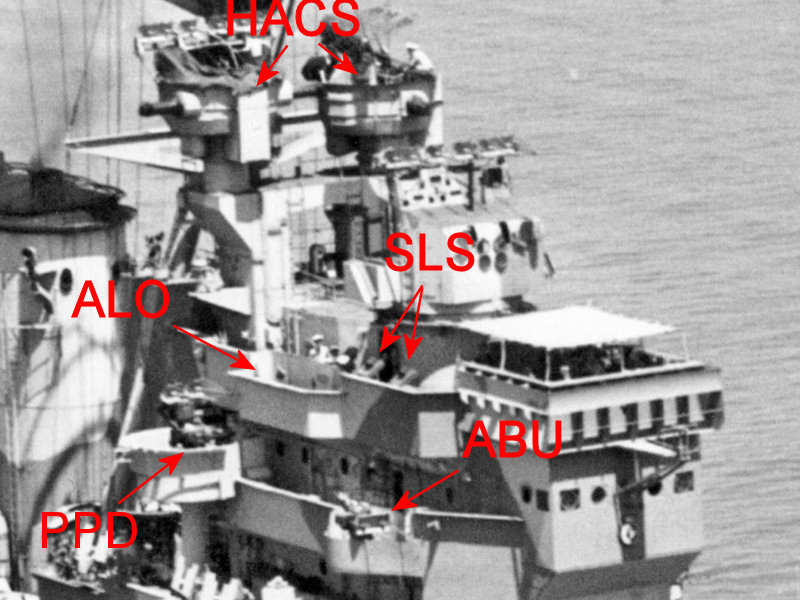
Here is a unique image of the ADP of HMS Hood. Some equipment is visible and was an unknown to me before starting doing some research. If you want to learn more about how and why the bridge of a British warship was equipped, I suggest reading The British High Angle Control System (HACS) by Tony Tony DiGiulian at the navweps website or the High Angle Firing chapter in the Gunnery Pocket Book at the Historical Naval Ships Association.

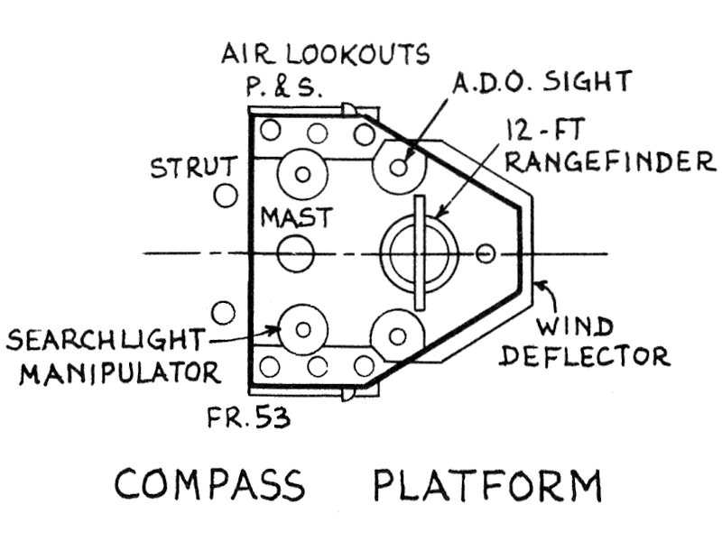
The ADP has a control team consisted of the Air Defense Officer (ADO) and his assistant. He has a special ADO sight that can indicate the to-be-engaged aircraft by relaying a target bearing. Such an ADO sight is thus an aircraft bearing indicator but this sight also functions as a star shell sight at night. The other ADO sight is manned by his assistant, so two of these sights are present. There are six so-called Air-Lookouts (ALOs), three on each side of the ship’s bridge. Each ALO continuously observes an arc of the sky around the ship, watching for aircraft to appear. The ALO uses a position with a pair of binoculars. Once an aircraft is spotted and marked by the ADO, the High-Angle Control System (HACS) will determine the target’s speed and bearing so that it can be engaged by the heavy anti-aircraft artillery. Each large capital ship was typically fitted with three or four of such HACS directors. The model of the HACS is described here. Next to the HACS directors, a series of close-range pompom directors are fitted. HMS Hood was fitted with one such director for each pom pom gun, one Mark I and two mark IIs ). The pom pom and HACS directors in the Royal Navy were all fitted with the Yagi radar aerials later, but HMS Hood was sunk before those radars were fitted. One piece of equipment present on other ships that probably would have been fitted to HMS Hood was the Auto-Barrage Unit (ABU) that determined the range of the enemy aircraft, in order for all anti-air guns to fire a single barrage.

Several directors for the searchlights were also present next to these air-defence positions. There is a single searchlight sight per searchlight, but as the two ADO sights can also act as a searchlight bearing indicators, HMS Hood was fitted with four additional searchlight sights.

The captain himself also has a bearing indicator that was placed on HMS Hood, but not on the inside of the bridge probably due to space constrains. On the King George V class, these sights were placed inside. A final sight, according to John Roberts, is a UP sight placed near the upper ADP of HMS Hood. No information was found on this particular sight.

So, the typical equipment found on RN warships is one pair of captain sights, a pair of ADO sights, two pair of searchlight sights (depending on the number of searchlights), three pairs of ALO sights, a pompom director per gun and a number HACS directors. The latter is the only one that is clearly visible on warships.

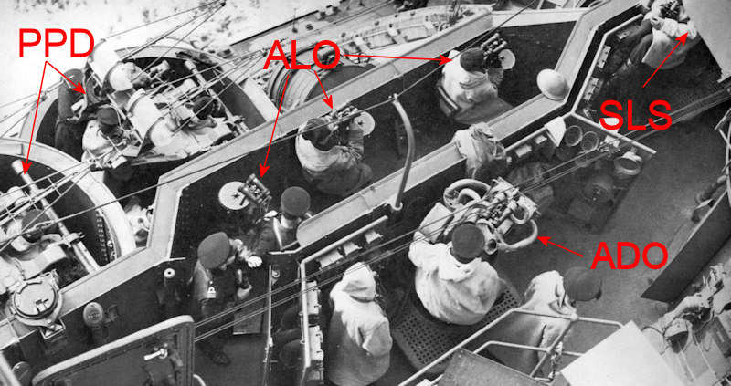
This image of HMS Prince of Wales’ bridge shows the ADP most clearly. From this picture follows that the sight on HMS Hood’s ADP is the same. The three ALOs are seen clustered together with the pom pom directors fitted a level lower. The searchlight sight (SLS) is just out of view.

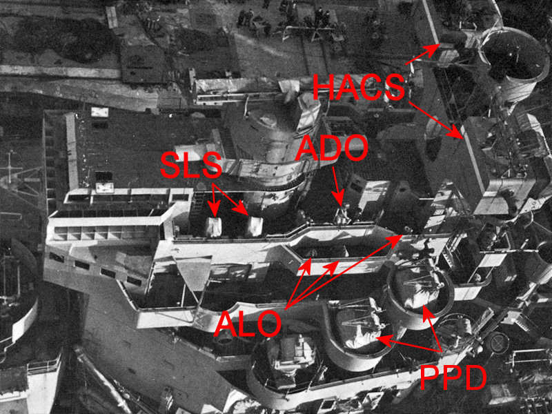
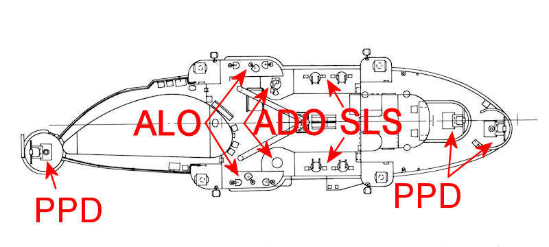
A clear top view of the bridge of HMS Duke of York. The three ALOs are well visible. HMS Prince of Wales and HMS King George V have their ALOs clustered together in a single position, but one of the ALOs aboard HMS Duke of York appears to be placed a but further aft. The searchlight sights (SLS) are seen at left below the main fire control director and are wrapped in covers, as are the pom pom directors (PPD). The captains sight is inside the fore bridge and is not visible.

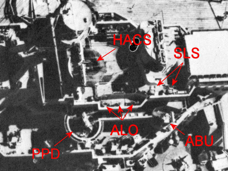
An excellent top view of HMS Queen Elizabeth, clearly showing the six ALO positions and searchlight sights (SLS). The ADO is not visible, but might be located in the fore bridge, as with HMS Warspite (slightly different bridge layout). The ABU is visible bottom right.

A very clear front view of HMS Queen Elizabeth showing the searchlight sights (SLS) and the ABU.

This schematic of the bridge of HMS Victorious shows the same equipment as on the battleships. Even with everything clearly in the open, I haven’t been able to find a good picture of the bridge of a carrier.

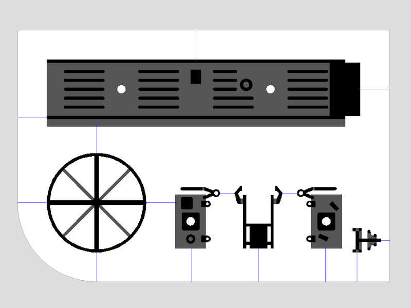
Now that I know what to look for, this equipment is visible on most other larger ships and even on monitors such as the layout above indicates, but the information on bridge equipment of most of these images is poor. If you flip through Raven and Roberts Battleships and Cruisers volumes, you’ll notice many (unannotated) positions of the ADP equipment corresponding to the number of directors I now expect on board these vessels.

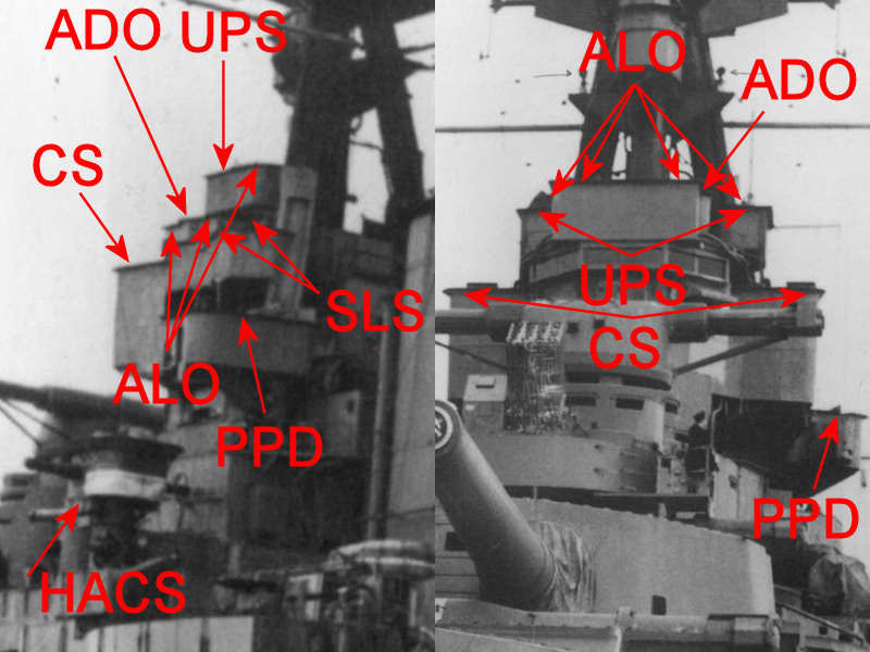
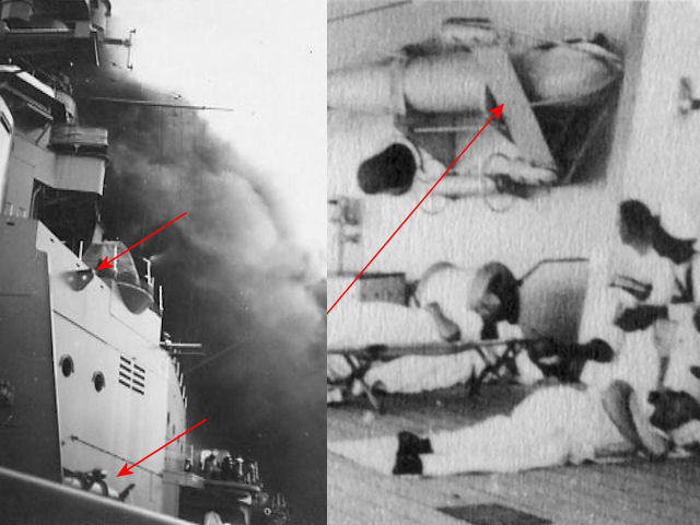
So, here’s a clear image of HMS Hood showing the location the Captain’s Sight (CS) and UP sight (UPS) as well. This clear image indicates that it is impossible to see any of the items on photographs as described above and the first image in this post of the ADP is the best there is as far as HMS Hood is concerned.

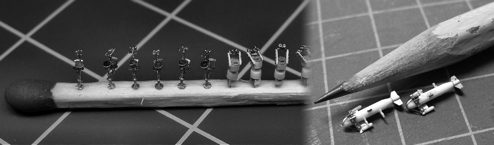
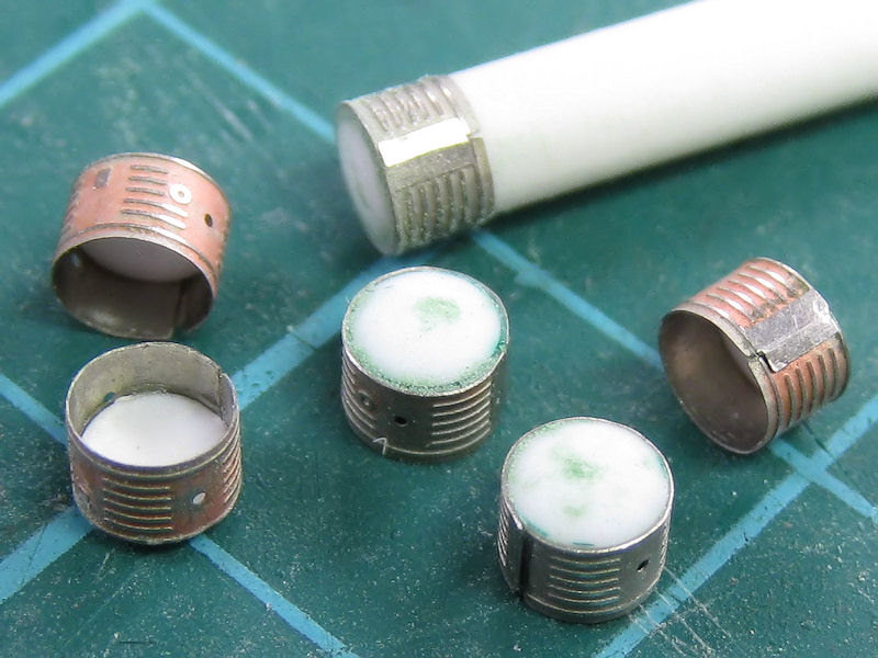
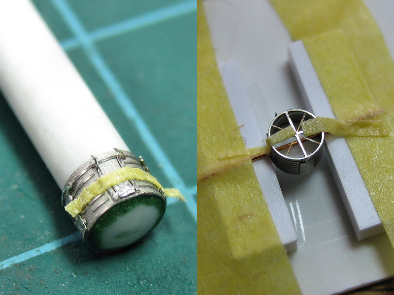
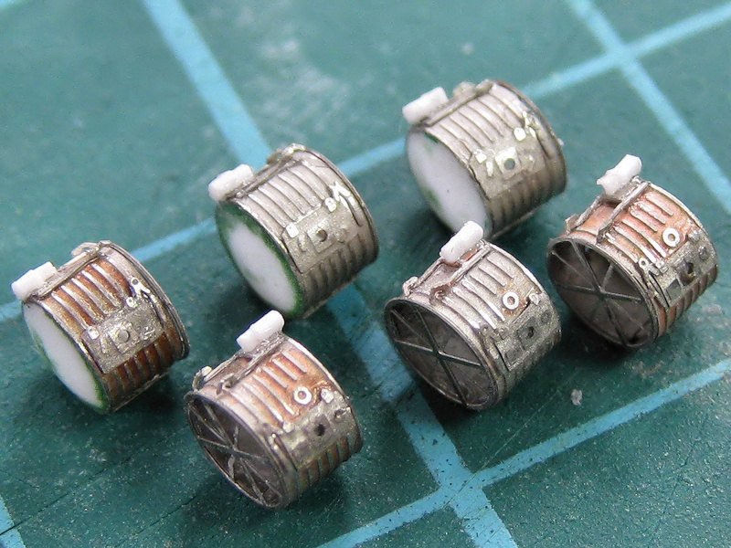
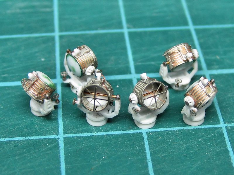
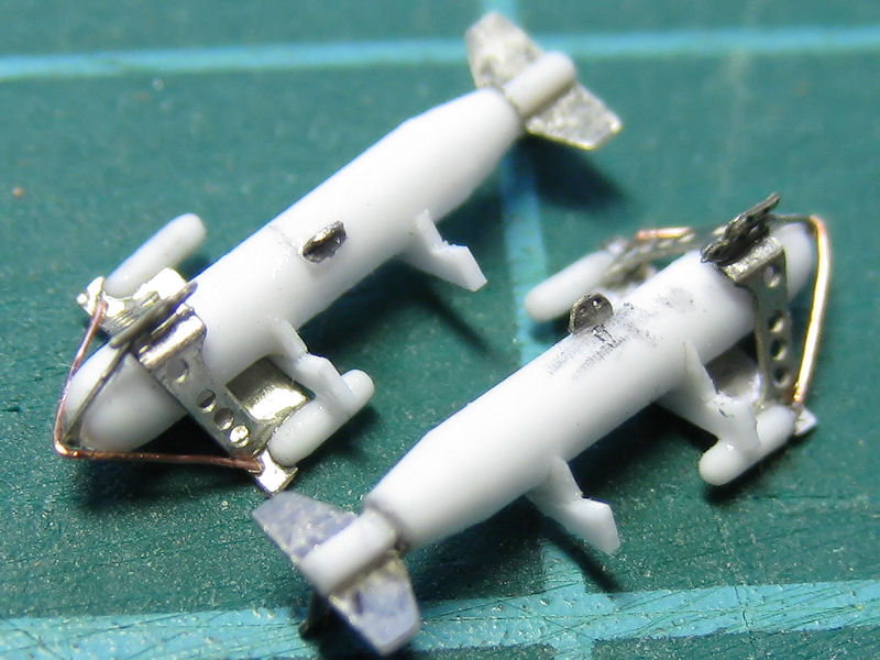
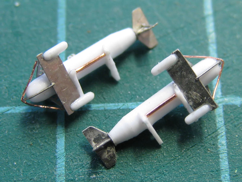
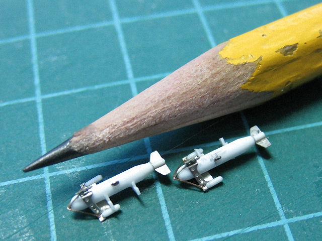
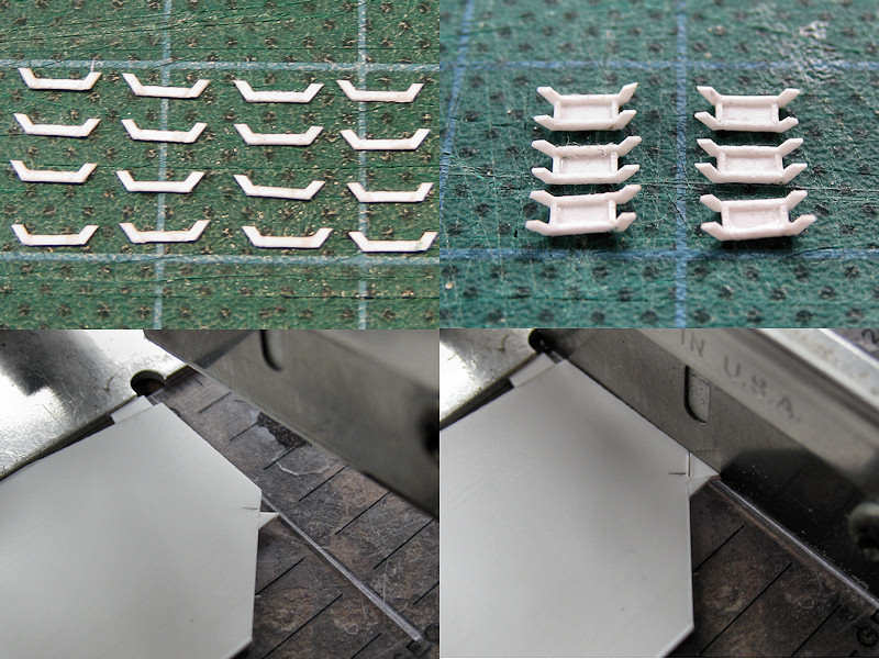
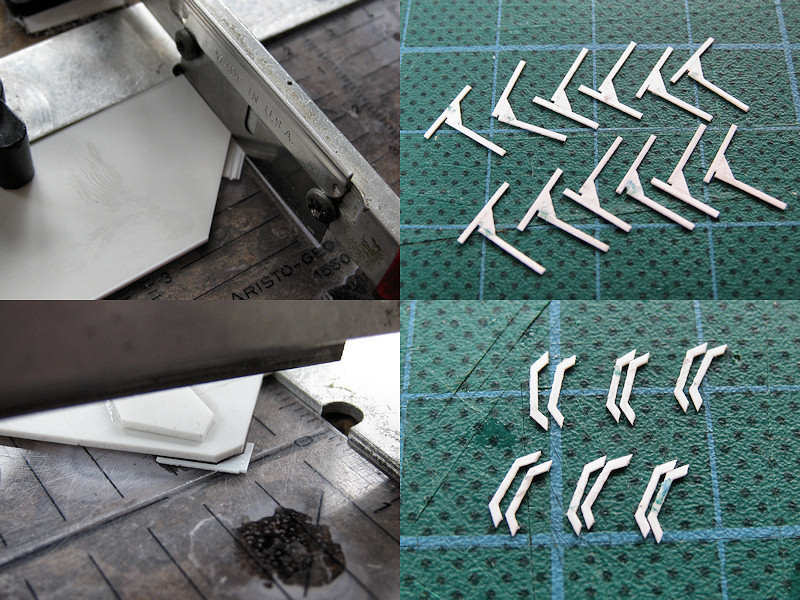
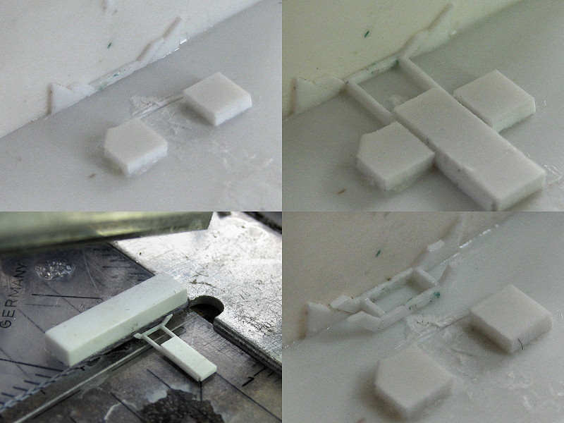
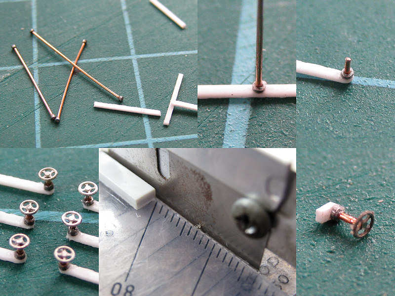
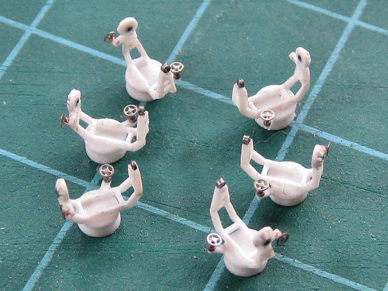
Part II of this post will show the individual units in detail.

Searchlights, part I

The large 44″ searchlights of HMS Hood were one of the last items of which I did not have good information except for a few pictures. Fortunately, John Lambert issued a series of drawings, L/O/162, although he mentions it’s the Mk VII of 1942-44, while Hood was sunk in 1941. I ordered them anyway and initially thought they were wrong as the frame didn’t match the photographs. However, I found out that nearly all pictures of the searchlights showed their port side and that I somehow thought the unit was symmetrical. On closer inspection it seems the drawing of the searchlights is as good a match as far as I can tell. This picture shows some of the best images of the searchlight. The images at left ware taken of HMS Onslow (top) and HMS Prince of Wales (bottom) with HMS Hood at right.

I intend to build the searchlights in two parts. The frame is mainly built in styrene (can’t see how to make a photoetch part that I can physically fold into the frame shape) and the projector itself mainly as a photoetched part.

I started with strips cut to shape for the frame and gluing them into the shape shown right. The front and rear should angle back about 8 degrees and this first attempt resulted in very uneven parts. It’s not so well visible in this particular picture but when continuing to add the rest of the frame, the part didn’t really work out. On to the Mk II miniature frame! This time, I spent some more time pondering and I eventually took a slightly different approach by cutting triangles first. At the bottom the mould for the chopper is shown. I use this approach a lot to cut angled parts to size. At right you can see a small template triangle in place to position the template. After a few sizes of triangle, you end up with the size you need (there’s always a slight difference in the template and copy size, usually about 0.1 mm.

Top left shows how to prepare large amounts of strip at an angle. Works pretty well, but right shows the easier approach; strips glued to the triangles. Now it’s just a matter of chopping the parts to size using another small mould. I always have large cheap styrene sheets laying nearby to spend on such actions. Two chops later and the front and rear base frames are cut to size much more consistently (and easier) than adding strips cut to size.

The next mould is a small plate angled forward 8 degrees and placeholder strips for the frame. The two blocks are for positioning what’s shown at right; two strips glued to a center block that acts as a spacer (and makes it easier to handle as well). Add a bit of glue and it’s fixed. Next, the part is cut to size and the same mould is used to glue the second frame. All parts were given some superglue in the corners. Now both the front and end plate are at the correct angle. Using a few moulds seems to be a lot of work but in the end the result was less work, resulted in less rejected parts and the parts more consistent in shape than when not using the moulds.

The top half of the frame was built from strip drilled in using my new drill press which I bought for the occasion. The side detail was built from a small ring, a small tube and some triangles.

This part was sanded to size and added to the frame. I made another ring for the searchlight bearing and checked if the part was nicely aligned. The hand wheel was then added, starting from a strip drilled in with a small 0.3 mm drill using the drill press. I start using thicker and slow-curing CA more frequently when bonding metals as the photoetch parts do not allow most of the other glues I have to stick.

The second hand wheel is being constructed from a small ring and strip. It barely survives the chopper! The end result is a small part to be added to the searchlight base.

Here’s the completed frame. The base part is made using my new lathe The lower base part has a conical shape and a 2mm gap so that it can be fitted easily on a disk on the model. The top part of the base is a small disk but with a very small 2mm extension so that it fits concentrically in the lower base part.

This is the design for the lantern which will be nearly all photoetch except for a small disk to close the part off. I couldn’t add all the required detail in a double-layer part, so I made three additional part to be glued onto the main part. The two parts for the side will be aligned using some rod, the top part will be aligned using the small square visible in the middle of the main part. Should be a nice folding exercise!

Go on to part II.

Copyright © 2024 On The Slipway

Theme by Anders NorenUp ↑