
Updated may 2012: added information on the CF25 binoculars and acknowledgement & permission to use Frank Lagorio’s images of the binoculars.
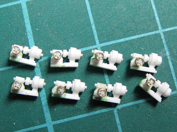
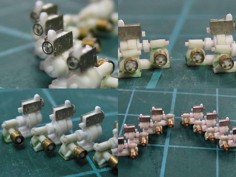
Continuing from Part I , where I pointed out what goes where, here I have some images of the individual stands.
I collected nice images of all the bridge equipment components, trying to figure out what was what. I flipped through well over 15,000 images in online archives, probably missing a few here and there. I even bought a second-hand book because it contained a single good image of the air-defense officer’s sight. I put the best images in a CAD program and estimated the dimensions for each sight. Crew should be able to stand behind the sights at eye level, they should not be higher than the bulkheads they’re behind, and they should scale properly with each other, and so forth. I know that one Air-Lookout Sight is fitted to HMCS Haida, but that’s a bit out of the way for an actual measurement. Still, I ended up with some probable and consistent dimensions, or so I believe. At least most of these sights have one thing in common: the binoculars. Not the most accurate frame of reference, but still.
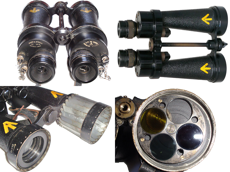
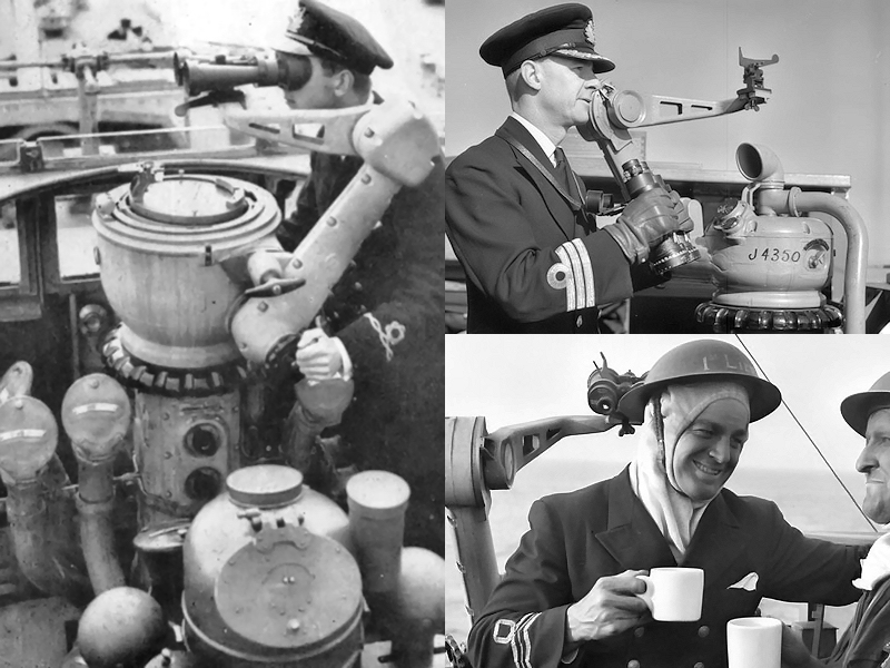
The binoculars are Barr & Stroud CF41 Admiralty Patterm 1900 night binoculars fitted with with built-in filters (yellow, green and polarizing). According to the Dock Museum, it measures LxBxH=235x170x90 mm, or about 0.67mm long at 1/350 scale, close enough to the 0.69-0.70mm I estimated from photographs (3-4% off). The bottom left binocular is actually the CF25 Admiralty Patterm 1949 with a 7×42 magnification type used primarily by observers of the Fleet Air Arm, not the larger CF41 with a 7×50 magnification. The objectives are fitted with telescopic sun shades/spray shields, explaining the most obvious visual differences as seen bottom left. There’s quite a few people collecting them and a few of the better images of bridge equipment were found on binocular fora (none that mattered for HMS Hood, unfortunately). These images were using with permission from Frank Lagorio’s Flickr Account. You can pick up a pair on ebay from as little as 30 pounds; quite cheap as apparently many of these units suffer from prism separation. Note the yellow Admiralty arrows, designating acceptance into the navy. So, if you manage to build 1/350 bridge equipment and then manage to get 1/350 binoculars: they should have a pair of yellow dots.
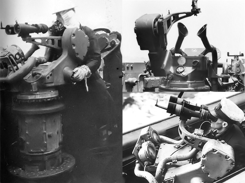
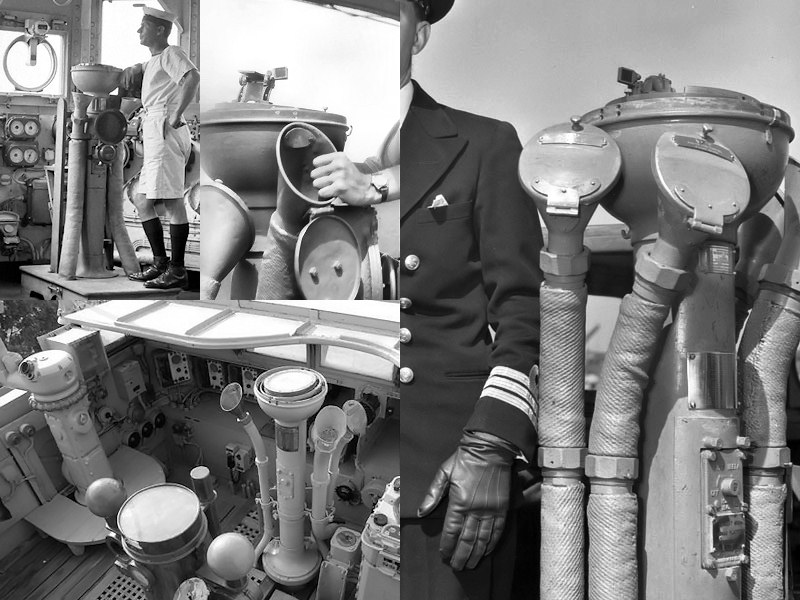
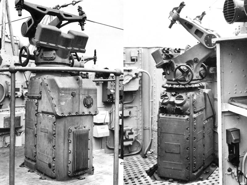
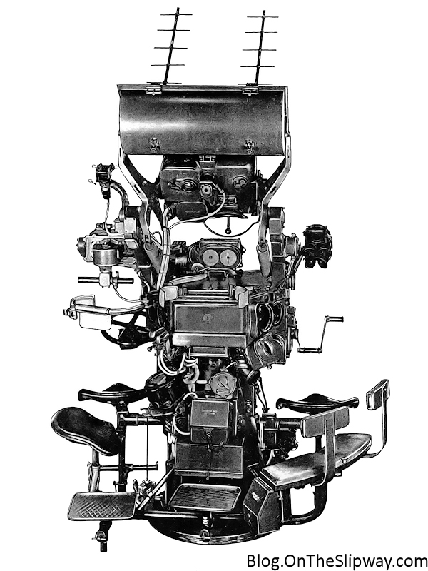
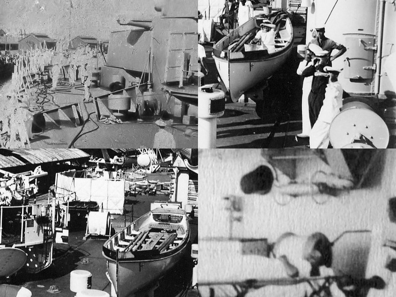
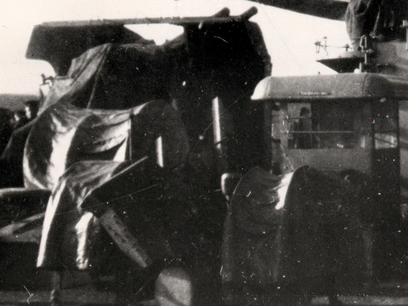
This is the air-defense officer’s sight; quite bulky. . A chair is fitted to the pedestal of this director than apparently can be swung out of the way. It appears that the voice pipes can be mirrored for post side and starboard units (compare the left and bottom right image).
I used these images to make a simple CAD drawing. The chair can be seen at right at a near-ninety degree angle with the top of the unit. The center-bottom image is taken aboard HMS Hood (mirrored).
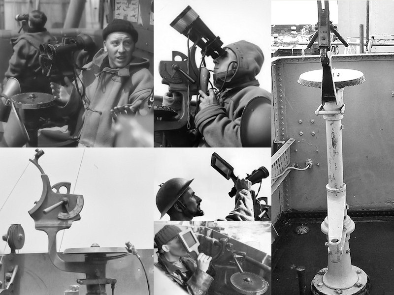
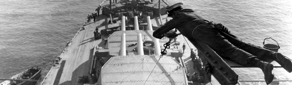
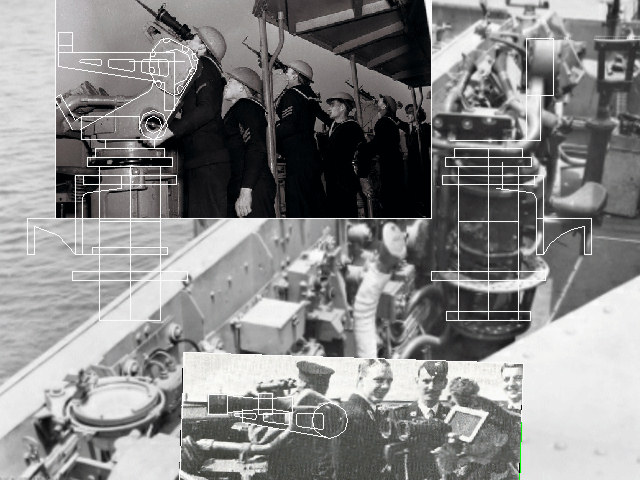
Here is the Air-Lookout Sight (Called Sky Lookout by the USN). It’s pretty well covered, that is, now that I know what it looks like. The top is black with some lettering. Notice the aircraft recognition chart in the top left image of HMS Suffolk and the sunblocks in the lower-center part of the image. I noticed a sailor on the image of HMS Hood’s air-defense platform carrying this (one image up) and it appears to be standard issue for the lookouts.
Here’s the model interpretation, consisting of a few etched and CNC-lathed parts.
Now, in my previous post I mentioned a director for the UP launchers. However, in the Admiralty Fleet Order C.A.F.O. 2163.— 7-in., U.P. Mark I Equipments. Removal from Ships when replaced by Oerlikons (G/T.S.D./864/41 6-11/1941), a transcript of which is present on the official HMS Hood site clearly states that Air Look out sights pattern 12951 should be demanded from the nearest Naval Store Depot for each U.P. sight surrendered when these sights have been used in lieu of Air Look out Sights. So, are ALOs normally used as UP launcher sights?I do not see any unknown sight on HMS Prince of Wales’ bridge when fitted with the UP launchers, so I assume so.
Here’s the searchlight sight, with only one proper image scanned from Raven & Roberts British Battlecruisers of WWII book. This unit is clearly modeled by John Haynes; paying more attention to his work might have been a time saver.
and the CAD drawing including etched parts. I didn’t bother to add all etched parts, being nigh invisible when placed on the bridge.
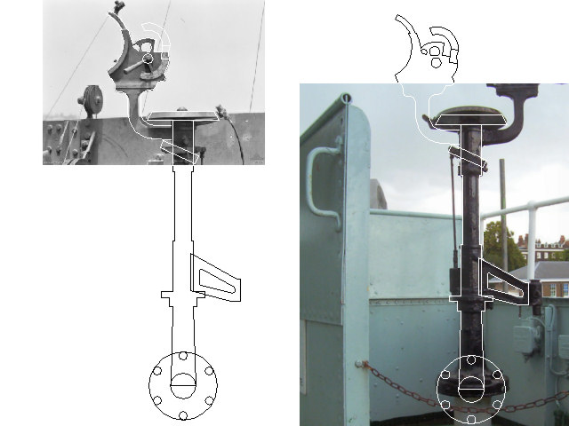
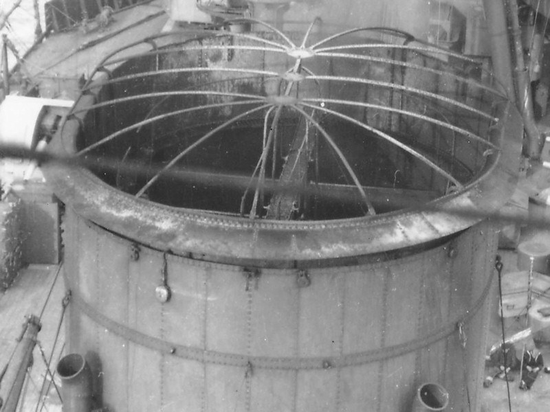
A Perolus is fitted to the center of HMS Hood’s air-defense platform. The model hasn’t been completed yet. Note the sight at the bottom left image, far left.
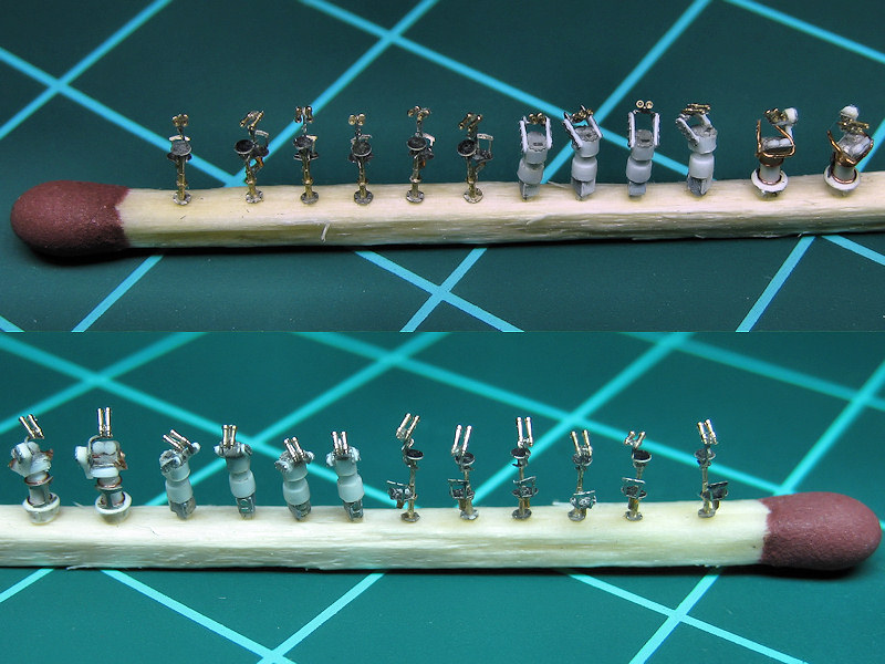
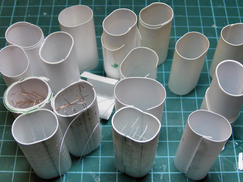
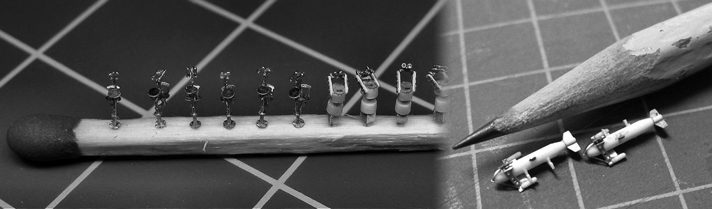
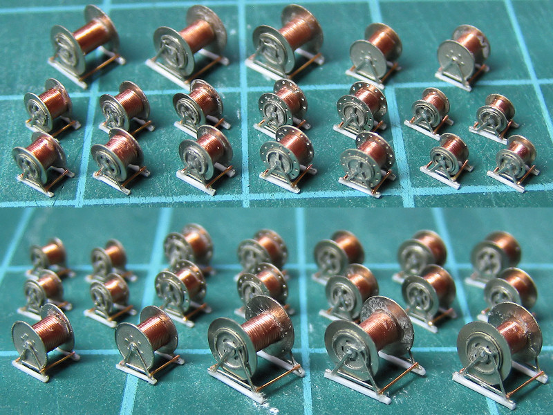
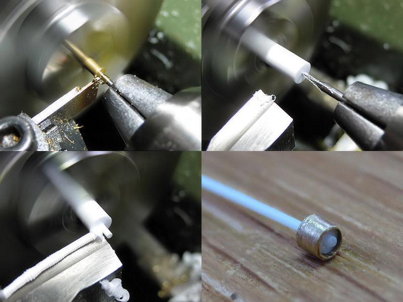
Here are the models for the ADOs, ALOs and SLSs. Don’t worry, this is a large match. I had a few parts lathed by MASTER; I wanted to have the binoculars to be hollow and just couldn’t do it using my own lathe. As I needed 30+ parts, reproducibility became an issue. This is quite problematic when you have trouble with just one decent part. MASTER could actually get all (yes, all) the detail into these small parts and did an excellent job. They also milled the pedestals and the Vickers Valchorns (not shown). The parts were tricky to make, naturally, but the binoculars where quite easy; note I added the binoculars with and without the sun shades randomly. The chairs for the ALOs were first glued to a brass wire, then to an etched part and then to the pedestal. Clearly a part too many! It’s easy to get lost with the design of etched parts when they fill a 24″ monitor. I lost nearly no binoculars or chairs, but a lot of chair supports. The chairs for the ADO have yet to be added. No wire in the design here, fortunately.
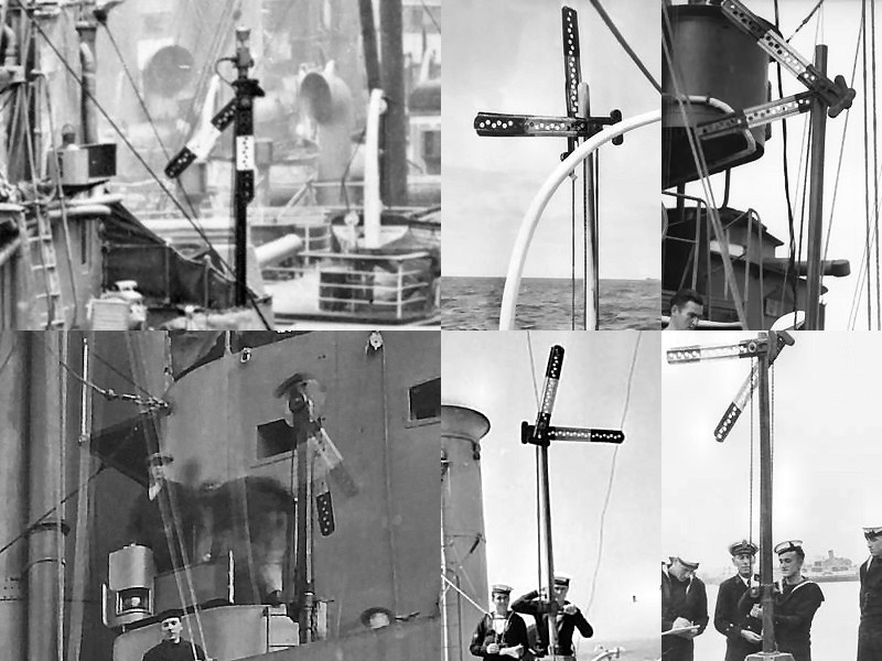
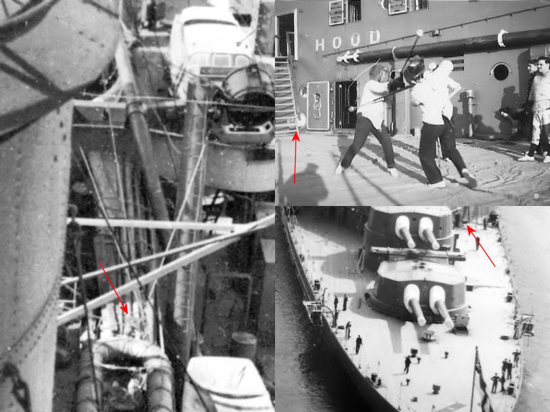
A semaphore is not bridge equipment in the sense it’s a director or range finder, but is typically placed near the bridge with the other signalling equipment (lights, flag lockers). There was some discussion on a forum what the colors of the arms were (perhaps yellow/orange, as for the semaphore flags), but the website Royal Signals mentions that most signal arms were either white or black, or a mixture of both. […] On the ship there were often two types, the Mast head version with arms nine feet to twelve feet length, and the “bridge” mounted version […] with arms of six to eight feet length. I have my etched part at 5ft and they appear over-scale to me. Anyway, note the pattern in both colors and in the holes of the semaphore arms. These will be constructed when my model is being painted. The images are from random vessels with HMS Hood bottom left.
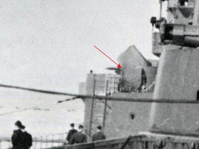
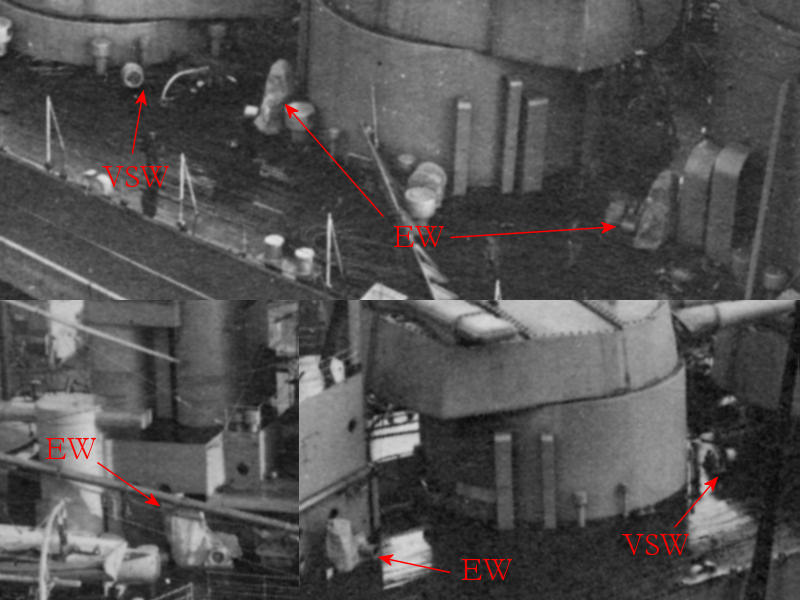
Next to the equipment known to be aboard HMS Hood, I have a few other close-ups I collected. These appear to be captains sights, indicative by captains near them (I think this makes sense).
There is supposed to be a target bearing indicator on the upper bridge wings of HMS Hood just below the air-defense platform and I assume it’s some sight; not another ADO. The left one certainly wouldn’t do , but I have no idea what type it could be. The right one would do; not visible in a photograph without the binoculars fitted.
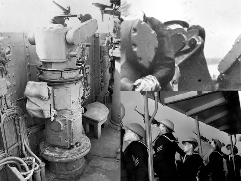
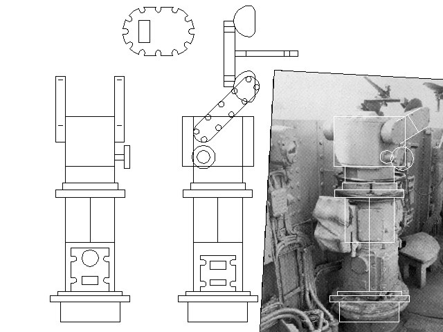
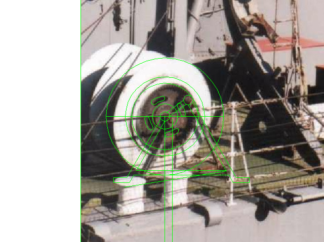
Another nice set of sight variations, shown quite clearly. This is the Pelorus Sight.
This last one is the universal sight, a sketch of which can be found at the Historic Naval Ships Association. This unit was (amongst others) fitted to HMS Vanguard.
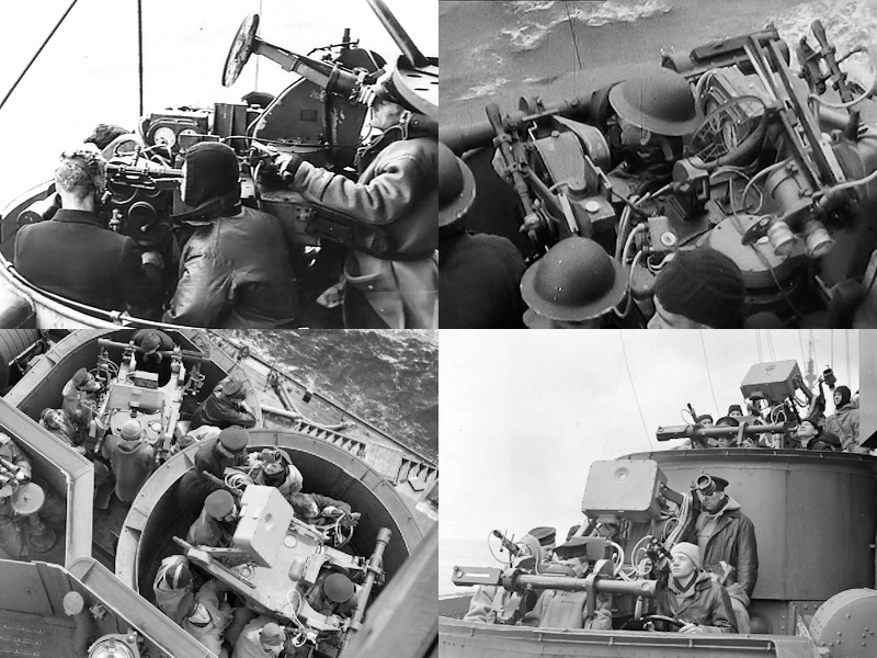
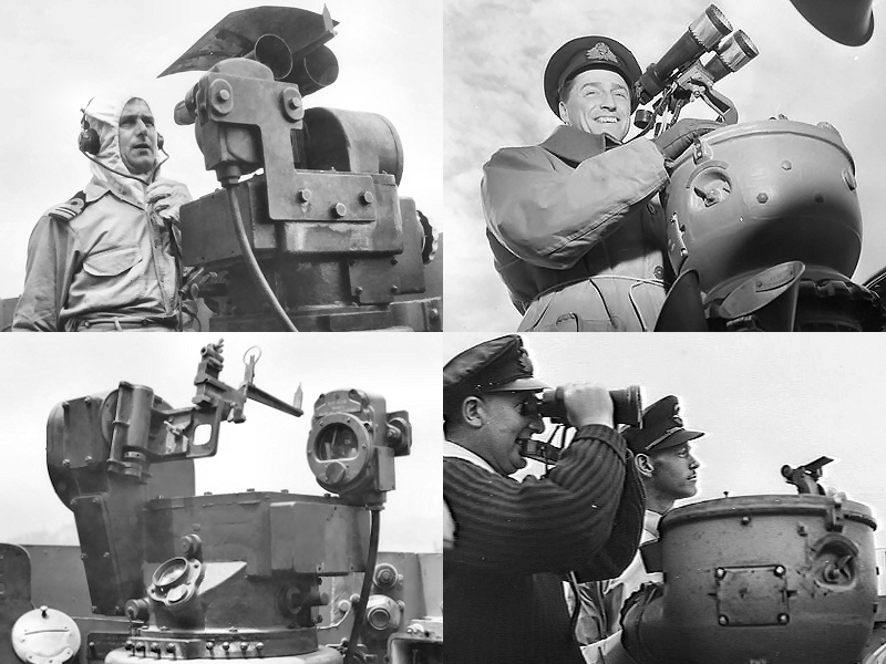
The Pompom director Mk I was described here. Not much was found for the Mk II and Mk III, but I have some images of the Mk IV to throw in so why not. The Mk IV was introduced in 1940 and can be seen aboard HMS Prince of Wales and HMS Kings George V (shown at right; note the absence of the radar aerials top right). Only the top-left image shows a Mk II/III. I have found not other photographs of the PPD Mk II/III. Fortunately I have the drawing from John Lambert Plans showing the unit in detail. A replacement of the model I have will be built later, with more etched parts and additional detail.
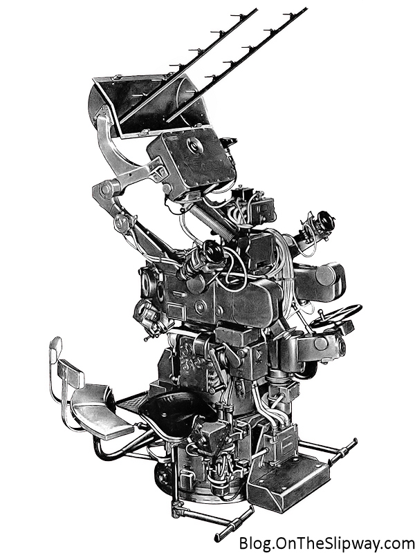

The three images shown above are all Mk IV pom-pom directors. Note that these images show the director without the optical rangefinder which was removed in March 1944 from most units to reduce crew size.
One unit I mentioned in part I was the barrage director. I haven’t found a good image except one you can look up at the Australian War Memorial. The UK National Archives contain a pamphlet on the unit but the costs were a bit too high for this blog post.
Should you want to consult the Austrialian War Memorial (AWM) or Imperial War Museum (IWM), check out the following images:
AWM: 0356, 00313, 00627, 016988, 017502, 017637, 029536, 029538, 029562, 075411, 078120, 084640, 084641, 084642, 084644, 084645, 089369, 110179, 112191, 112341, 112355, 112360
IWM: 000872, 000874, 000876, 000878, 000888, 002873, 003651, 003883, 004218, 005667, 007696, 008432, 011001, 011213, 011803, 018039, 022617, 024208, 024326, 112355.


