I sent my second etch to the etchers yesterday evening. I spent quite a few evenings preparing the drawings of all the parts I might need and all the parts I needed before but botched up in the previous etch set. This explains the low number of posts the last few months. The new set contains the railing, new stairs, new funnel parts, flag lockers, cable reels, and more. I also added the quad and octuple pompoms (two version of the latter) as possible masters for a volunteering manufacturer? I’ll go through it once the sets arrive. They should be complete by week 4, 2010…
Page 19 of 28
Radar Type 279M
As I explaining in my previous post of the main mast, the main topmast was removed from the main mast and replaced by the aerial for the Type 279M air warning radar. An aerial is an antenna in military terms. This system normally operated with a transmitter and a receiver array for the Type 279 radar (and later the Type 281). HMS Hood was the first ship fitted with the experimental Type 279M aerial, whereby the aerial was a transceiver array capable of both transmitting and receiving requiring only a single aerial. This is clearly sited on the radar page and this transcript on the official Hood site. If you want to know more, or even everything, about the Type 279 radar aerial, please go to the Royal Navy’s museum of radar and communications website, a source of information the likes of which I not seen before. I cannot find any more information of the Type 279M in particular, nor is it mentioned in the article “The development of Radar in the Royal Navy (1935-45)” by Alastair Mitchel in Warship, vol IV, pp 2-14, pp 117-134. The M designates the first major modification although the Type 279 was in itself an update of the Type 79, and other transceiver arrays are usually marked with a B (single mast version) and no other instances of an M variant were found.
Pictures of HMS Hood taken weeks before her loss do not show the aerial clearly. But, at least there is ‘something’ visible. Unfortunately, the Type 279M radar is usual a ‘something’ on a picture, showing itself barely visible high up in the masts of battleships and cruisers. One must also be careful, as the radar aerial Type 281 (fitted with a Type 240 IFF antenna) looks a lot like the Type 279 (fitted with a Type 243 IFF antenna).
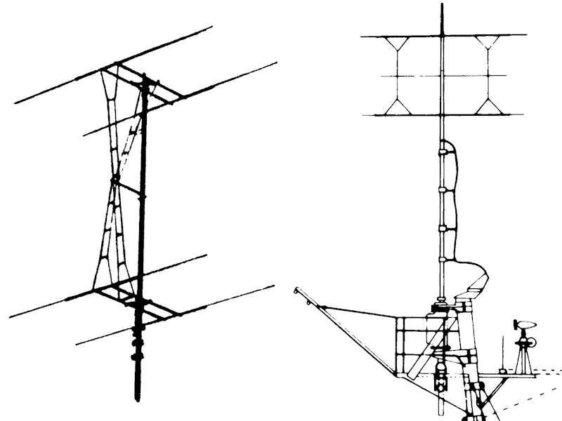
All these antenna do show to have a small service platform that seems to be standard on all vessels and Raven & Roberts “Battleships of WWII” & “Cruisers of WWII” show the same platform drawn on the masts. I assume that platform is of the same dimensions for both the Type 279 and the Type 281. The measurements of the aerial themselves are known, as the span of the dipole array is half the wave length of the system, and dipoles are a quarter wave length apart. The wave length was 7.5 m for the Type 279 radar
The left image is a drawing from Roger Hayward’s “Cruisers in camera” of the Type 279. At right, a picture is shown from Ross Watton’s “Anatomy of the ship: the cruiser HMS Belfast”, showing the Type 281. This was my best starting point for the Type 279M dimensions.
The best picture is from Roberts & Raven “BB’s of WWII”, page 387, showing the topmast of HMS Queen Elizabeth in 1941 and is the only good (if not excellent) photograph of the aerial. It also shows the gaff from the aft of the service platform that was present on HMS Hood as well. In order to access the platform, the ladder had to be on the front of the mast and this is visible on some pictures. The right half of the pictures shows the Type 279 (top row) and Type 281 (bottom row). Except for the differences in the aerials themselves, it appears that the Type 279 has one less masthead insulator and the platform support bracket near the mast is angled for the Type 279 and straight for the Type 281.
The mast of HMS Hood is seen “clearly” at left . Some cabinet is still present on the aft star fish. The right picture is reproduced from the Canadian Forces Base Esquimalt Naval & Military Museum with permission, showing HMS Hood in May or April 1941. The gaff is a clear indicator the radar platform was fitted and the platform and radar mast are visible, although just barely.
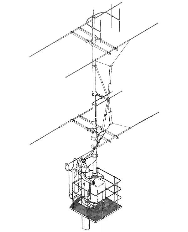
This image I found at the Royal Navy’s Museum of Radar and Communication. This picture (reproduced with permission) is absolutely fabulous, showing the Type 279 radar with the 243 IFF antenna in great detail, found here on the site of the museum (page 81/82).
Having now spent a few days flipping through my books and seriously searching the net, I think I can now make a cute mini 279 aerial.

Bridge equipment, part I
Nearly all resources of HMS Hood show the layout of the bridge equipment in the open air, though only as location placeholders. One good image is known of Hood’s Air Defence Position (ADP) showing a series of pedestals and smaller sights and range finders. Finding out which one goes where and what piece of equipment it is was the next challenge. In the end, it appears that HMS Hood is fitted with the same equipment fitted to all battleships, most heavy cruisers and fleet carriers. However, getting a good picture of that equipment is something different altogether as these smaller sights are usually placed in crammed positions that are visually obscured.
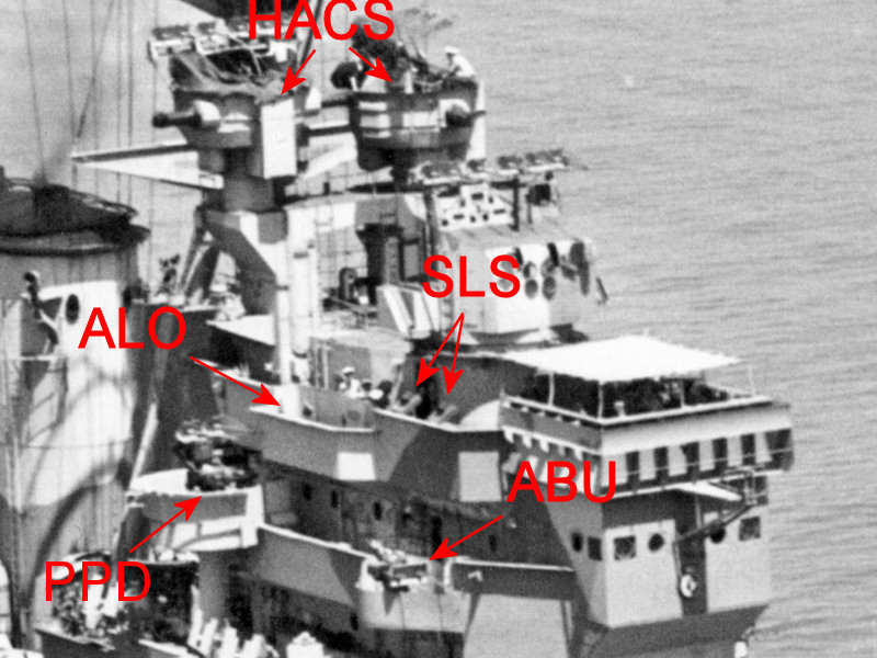
Here is a unique image of the ADP of HMS Hood. Some equipment is visible and was an unknown to me before starting doing some research. If you want to learn more about how and why the bridge of a British warship was equipped, I suggest reading The British High Angle Control System (HACS) by Tony Tony DiGiulian at the navweps website or the High Angle Firing chapter in the Gunnery Pocket Book at the Historical Naval Ships Association.
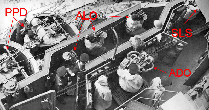
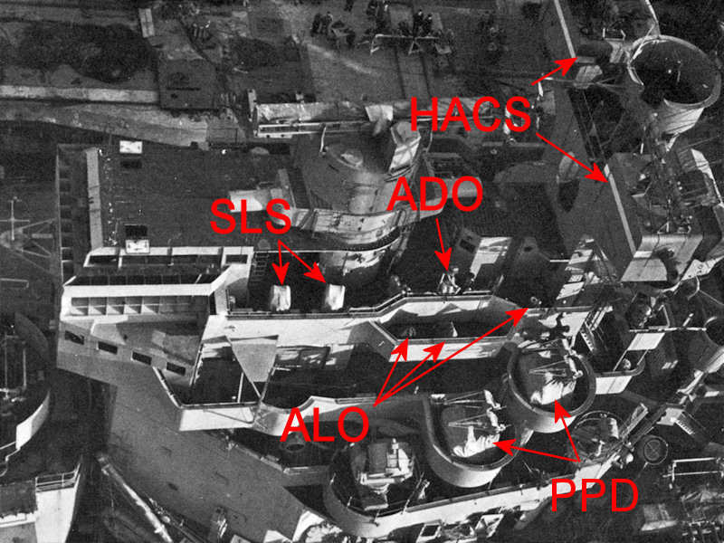
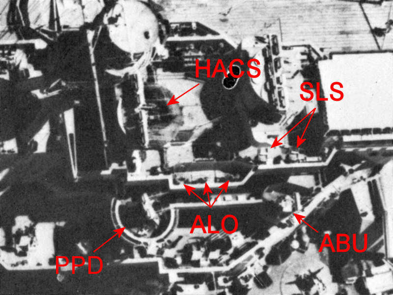
The ADP has a control team consisted of the Air Defense Officer (ADO) and his assistant. He has a special ADO sight that can indicate the to-be-engaged aircraft by relaying a target bearing. Such an ADO sight is thus an aircraft bearing indicator but this sight also functions as a star shell sight at night. The other ADO sight is manned by his assistant, so two of these sights are present. There are six so-called Air-Lookouts (ALOs), three on each side of the ship’s bridge. Each ALO continuously observes an arc of the sky around the ship, watching for aircraft to appear. The ALO uses a position with a pair of binoculars. Once an aircraft is spotted and marked by the ADO, the High-Angle Control System (HACS) will determine the target’s speed and bearing so that it can be engaged by the heavy anti-aircraft artillery. Each large capital ship was typically fitted with three or four of such HACS directors. The model of the HACS is described here. Next to the HACS directors, a series of close-range pompom directors are fitted. HMS Hood was fitted with one such director for each pom pom gun, one Mark I and two mark IIs ). The pom pom and HACS directors in the Royal Navy were all fitted with the Yagi radar aerials later, but HMS Hood was sunk before those radars were fitted. One piece of equipment present on other ships that probably would have been fitted to HMS Hood was the Auto-Barrage Unit (ABU) that determined the range of the enemy aircraft, in order for all anti-air guns to fire a single barrage.
Several directors for the searchlights were also present next to these air-defence positions. There is a single searchlight sight per searchlight, but as the two ADO sights can also act as a searchlight bearing indicators, HMS Hood was fitted with four additional searchlight sights.
The captain himself also has a bearing indicator that was placed on HMS Hood, but not on the inside of the bridge probably due to space constrains. On the King George V class, these sights were placed inside. A final sight, according to John Roberts, is a UP sight placed near the upper ADP of HMS Hood. No information was found on this particular sight.
So, the typical equipment found on RN warships is one pair of captain sights, a pair of ADO sights, two pair of searchlight sights (depending on the number of searchlights), three pairs of ALO sights, a pompom director per gun and a number HACS directors. The latter is the only one that is clearly visible on warships.
This image of HMS Prince of Wales’ bridge shows the ADP most clearly. From this picture follows that the sight on HMS Hood’s ADP is the same. The three ALOs are seen clustered together with the pom pom directors fitted a level lower. The searchlight sight (SLS) is just out of view.
A clear top view of the bridge of HMS Duke of York. The three ALOs are well visible. HMS Prince of Wales and HMS King George V have their ALOs clustered together in a single position, but one of the ALOs aboard HMS Duke of York appears to be placed a but further aft. The searchlight sights (SLS) are seen at left below the main fire control director and are wrapped in covers, as are the pom pom directors (PPD). The captains sight is inside the fore bridge and is not visible.
An excellent top view of HMS Queen Elizabeth, clearly showing the six ALO positions and searchlight sights (SLS). The ADO is not visible, but might be located in the fore bridge, as with HMS Warspite (slightly different bridge layout). The ABU is visible bottom right.
A very clear front view of HMS Queen Elizabeth showing the searchlight sights (SLS) and the ABU.
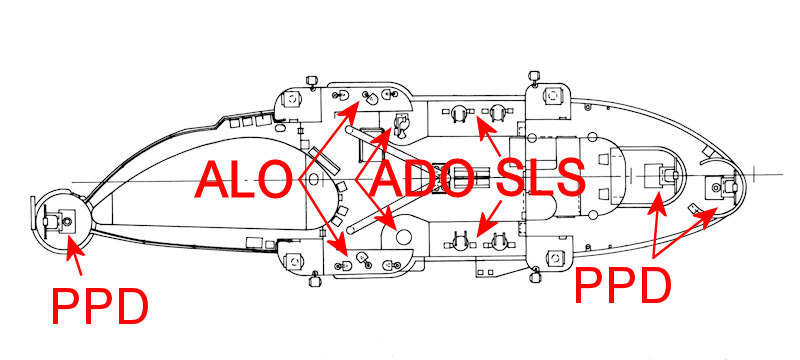
This schematic of the bridge of HMS Victorious shows the same equipment as on the battleships. Even with everything clearly in the open, I haven’t been able to find a good picture of the bridge of a carrier.
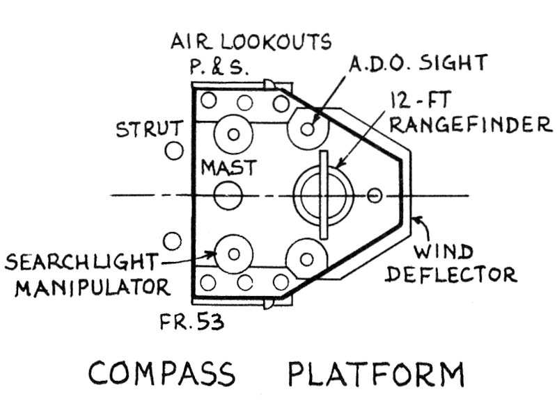
Now that I know what to look for, this equipment is visible on most other larger ships and even on monitors such as the layout above indicates, but the information on bridge equipment of most of these images is poor. If you flip through Raven and Roberts Battleships and Cruisers volumes, you’ll notice many (unannotated) positions of the ADP equipment corresponding to the number of directors I now expect on board these vessels.
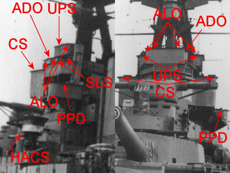
So, here’s a clear image of HMS Hood showing the location the Captain’s Sight (CS) and UP sight (UPS) as well. This clear image indicates that it is impossible to see any of the items on photographs as described above and the first image in this post of the ADP is the best there is as far as HMS Hood is concerned.
Part II of this post will show the individual units in detail.

Emplacements of the Vickers Quad Machine Guns
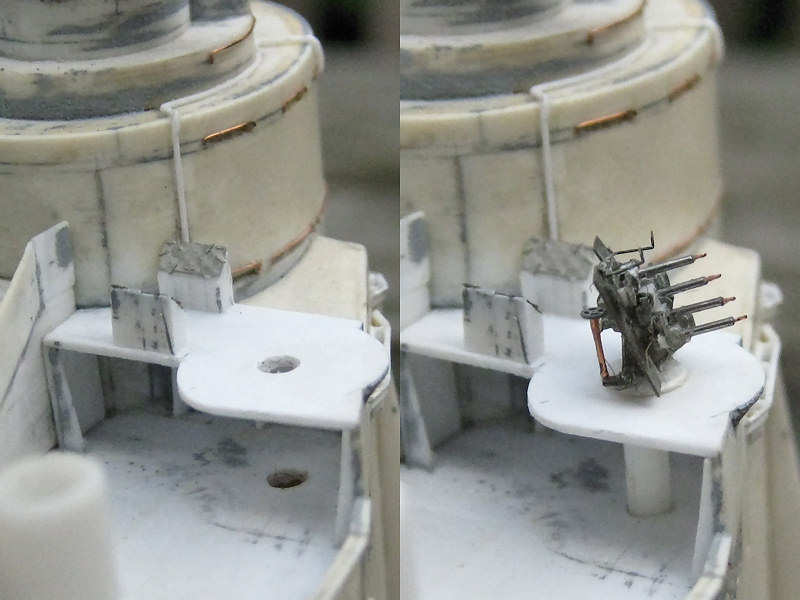
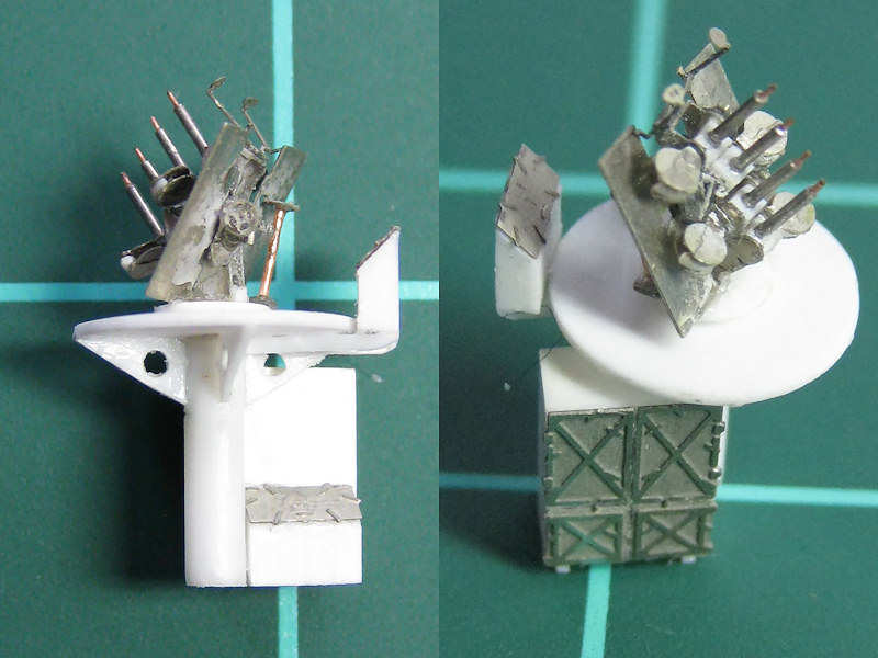
Here’s a view of the forward superstructure where the Vickers quad machine guns were placed. As you can see, the structure near these guns is open and show some signs of rearranging the bridge to get them open. A support pillar is almost certainly present, as is the case with the aft Vickers machine guns. I used my newly acquired drill press to drill in the bridge part and added the pedestal to the gun. It can be added fully painted without having to worry too much about masking. It also gives the gun a small handle while paining them. Two ammo lockers are present per gun, although I have no photographic confirmation.
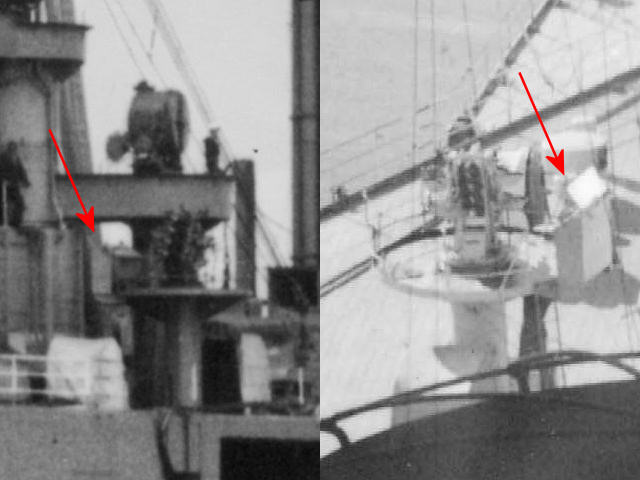
Photographs of the aft Vickers emplacements show that only a single ammo locker was added to the gun platform, so adding two is definitely wrong. This is confirmed by images of wreck debris where one pedestal was found upside down with only one ammo locker. Note in the right half that a small ladder is present and that only a very low single-bar railing is present. So, where is the second locker?
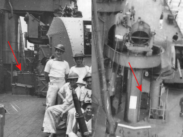
I think—judging from these two photographs from the offical HMS Hood site—the second locker is simply stored on deck.
The emplacements were made using lathe, as the pedestals are small tubes that hold both the guns and fit nicely onto the deck part (The gun is not glued into position). Of course, while writing this blog post I noticed that the locker on deck level for the port side gun was not fitted snugly against the pedestal as on the starboard mount, but some distance to toward the ship center. Ah well.


