Page 20 of 27

Proxxon Drill Press

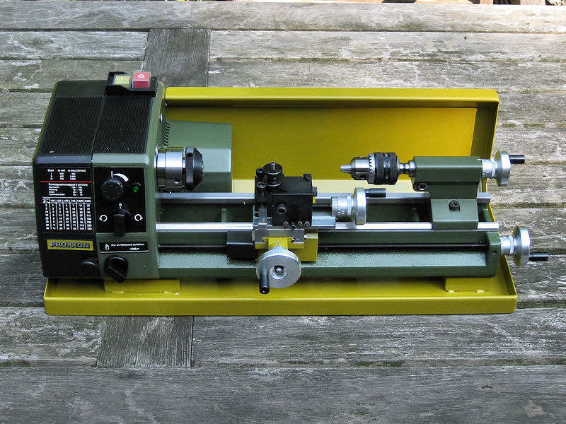
I bought a small drill press by Proxxon. It’s very cute and not so expensive. I previously used a drill press for drilling in the array of holes of the UP launchers. I tried to do this by hand, even drilling through a photo-etched template I had etched. But, no matter what I did, the results didn’t work out. When using a drill press at work, I found at that for such parts even a 0.05 mm misalignment shows with an array of holes, an error much smaller that I can achieve by hand. After all, the distance between the holes was only 0.1 mm. I didn’t have a good use for a drill press until now as I can always postpone certain jobs of the model, but I felt it was about time to buy one. Proxxon sells several, the one type being twice as expensive as the other and I suppose it has other redeeming features as well.

I already have the handheld drill of Proxxon (Micromot 50/E) and a Dremel. Dremel has a much shorter range of tools, mostly hand-held, and they always feel more like toys than tools. Being taken over by Bosch apparently didn’t really help. Their collets are flimsy and flexible, while Proxxon has proper steel collets. Sure, Proxxon is rather childish compared to the tools in the workshop, but those tools are quite expensive for the limited use on my workbench. On most Dutch websites, the Proxxon tools are even sold as ‘modelbuilding’ tools only. But it’s the extra’s of Proxxon that made me buy one. They have a very cheap compound table (27100) and (more importantly) a precision machine vice (24260) for ‘intricate and accurate working’. It’s orthogonal and flat and can hold very thin strips. This is what I intend to use it for, as most other vices are not so flat and orthogonal. Industrial vices that are flat cost far more than the entire combination I just purchased so it sounds like rather a good deal.

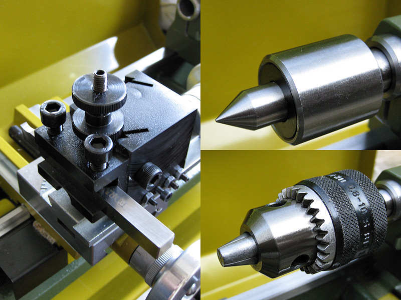
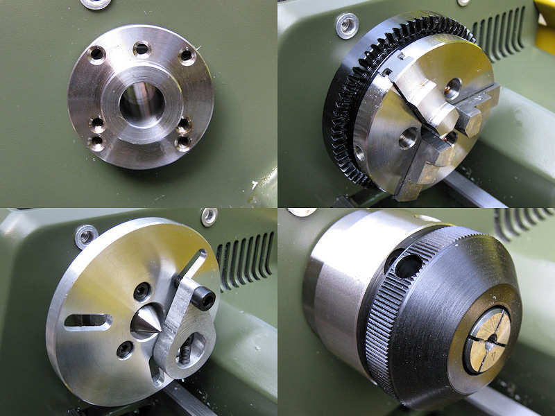
The drill press itself is the Proxxon TBM 220 (28128), “competent drilling of micro holes down to even 1/64″ (0.5 mm)”. What? That crude? The drill press uses the Micromot collet system, so that’s a range of six steel collets, the smallest being 1.0 mm and not being able to fix a very small drill at all. I thought I was really clever as my hand-held drill can remove the Micromot adapter and use a normal chuck. Image my surprise that the hand-held tools use a different size of drill-chuck. You can buy the “original German Röhm chuck for drill bits up to 1/4″ (6 mm)” but that one starts (!) at 0.5 mm. Hmm, I wonder who decided using two systems was a great idea.The other thing that was unnerving was the enormous slack in the compound table. Good enough for my modeling and admittedly: it is reasonably cheap at nearly 10% of the cost of a real contour table. I tightened it a bit, but it’s not really machining accuracy. Also, the adjusting screws are tightened themselves by M5 nuts. I don’t know about you, but I have several complete series of wrenches that all start at M6 so I had to use pliers. The first scratch in the paint was present before trying out the drill itself. I never understand why machines are not fitted with one size of screw or bolt but a mix of different sizes of screws and bolts using the slotted (ack!), Phillips, Hex socket and torque screws types ( I can spot 5 types just on the stand of the drill press). Why not use one size of hex slot? Also, the stroke of 30 mm of the drill press is quite small but I knew that when I ordered it. But what I should be saying is that the combination is actually nice value for money at three-hundred Euros. At least I think so, and the entire drill press has a small footprint which also comes in handy on a perpetually crowded modeling table.

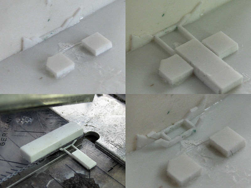
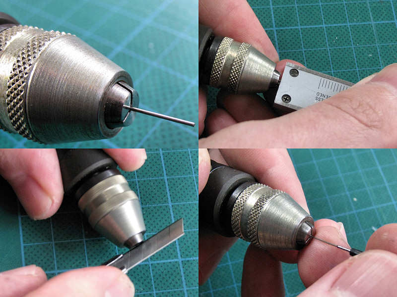
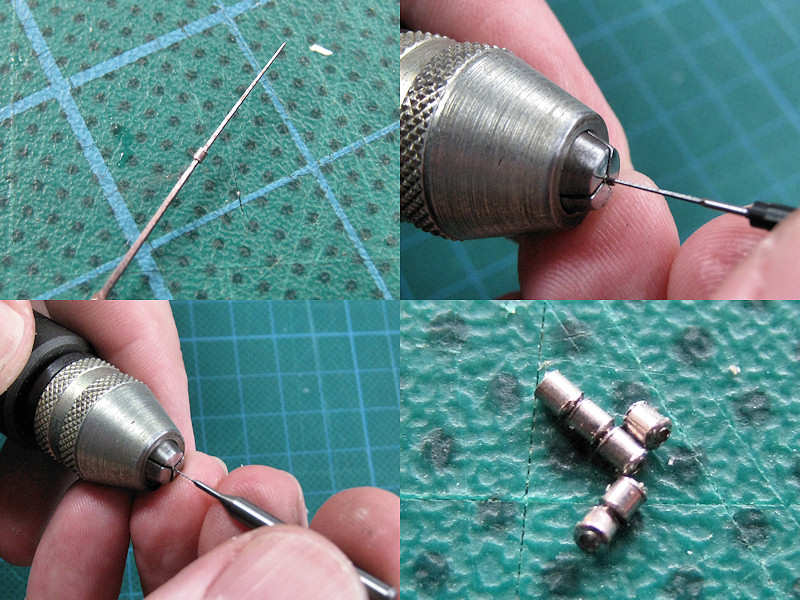
Upon starting to use it, I immediately found another severe deficiency of the Proxxon drill press: you cannot fix it at a vertically-fixed position. I solved this by throwing in a collet I didn’t use at the time to keep the drill in its downward position, shown top left. I then inserted a strip in the vice touching the drill and called that position ‘zero’, corrected for the radius of the drill bit. Ah, the macro-pic bottom left shows it’s not exactly centered.

I don’t have that many quality drills laying around as all but the most flexible miniature drills break quite often when using my hand-held pin vice. I found a source of cheap 0.3 mm drills (a second-hand seller, twenty times cheaper than the shop price). I pre-drilled in all the required holes with those drills for this particular part and finished them off using other diameters (0.4 and 0.5 mm) The parts (prior to sanding as my chopper isn’t that consistent) look fine and will be put to good use.

Pompom director Mk II

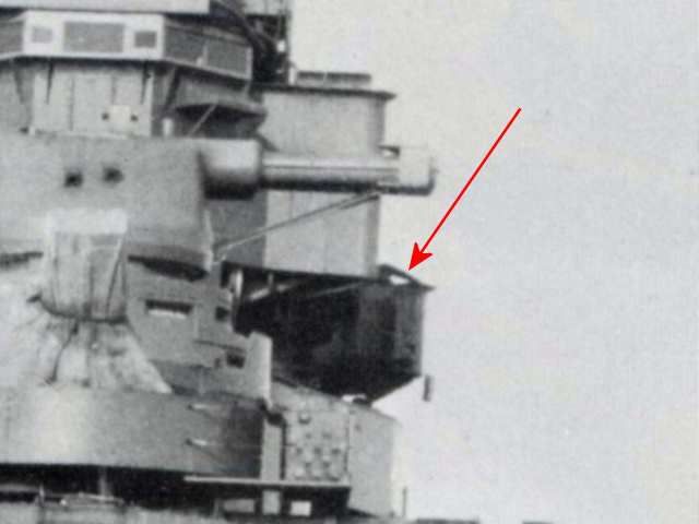
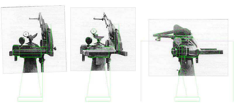
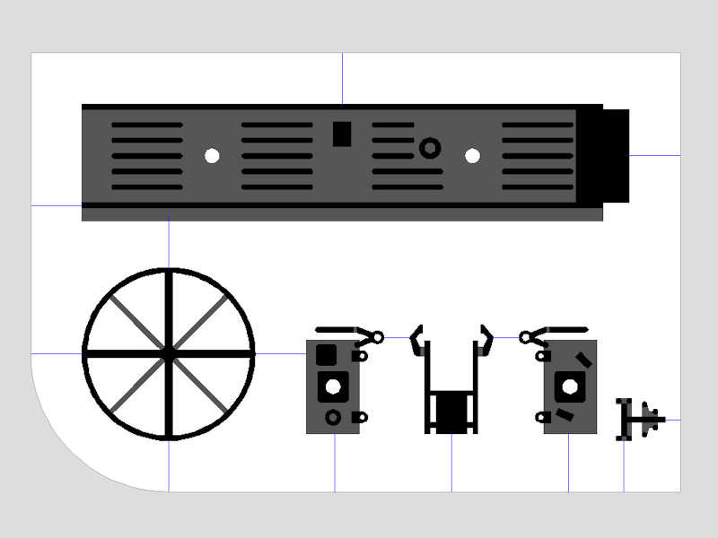
Each of the octuple 2-prd pompoms of HMS Hood is fitted with its own director. From the Anatomy of the Ship book follows they have been placed on the fore top (spotting top) in cylindrical emplacements and moved down to the fore bridge in 1936. A third director was fitted in 1938 to the aft searchlight platform when the third pompom was placed. Now, the third director is a Mk II while the first two are Mk Is. The Mk II is available through John Lambert Plans, drawing L/0/64. I was hoping that the Mk II and Mk I were comparable. They are not.

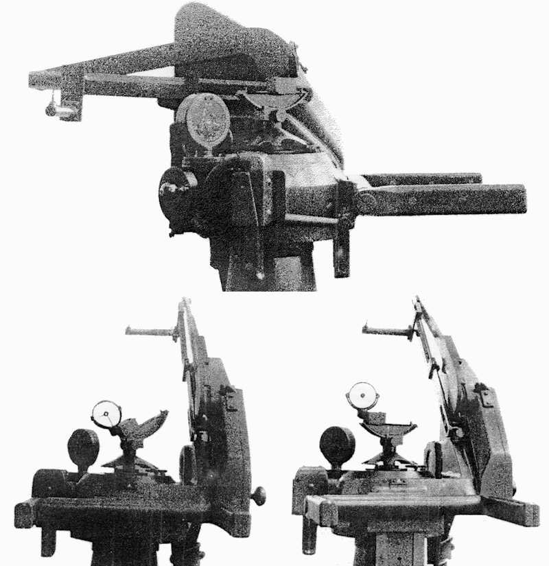
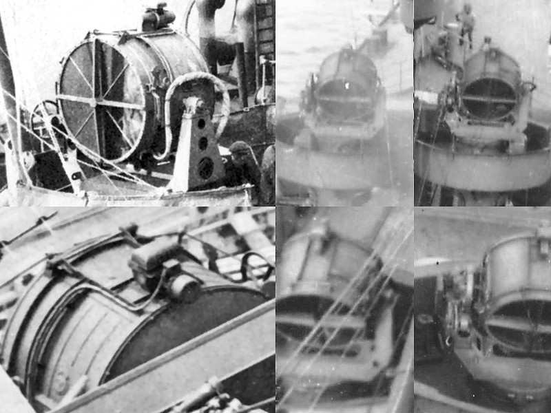
This is a picture of a pompom director Mk IV fitted with the ‘Yagi’ aerial that was used for the radar Type 282, 283, and 285 that were also to be fitted on HMS Hood. The director itself seems to the same type as the Mk IIs and MIIs.

This picture shows two pompom directors as seen on the bridge of HMS Prince of Wales.

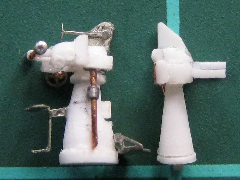
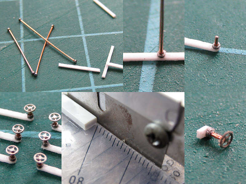
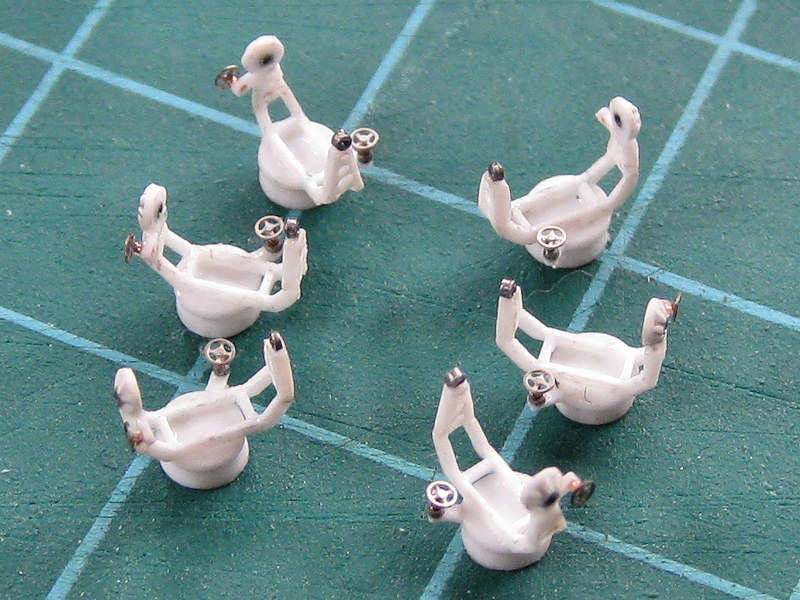
Here are the three models of the director Mk II with some etched parts, rod, and tube. The drawing shows great detail that can be added to these small models. The difficult part was cutting the tubing and adding the hand wheels. They kept falling off.

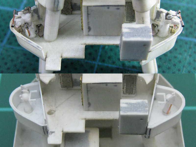
This image shows the directors at the correct location. However, they are much too large. They cannot rotate and the are too high to match any photograph of HMS Hood after 1936.

At left the aft searchlight platform is shown, indicating the location of the director. The top right image shows the location of the Mk Is prior to moving them to the fore bridge, the bottom right image shows them at their final location. From these images is well visible the Mk Is can hardly be seen.

Bridge Superstructure, part III

The parts of the bridge and fore bridge were already quite finished, until John Roberts posted the sketch below on the official HMS Hood site.

This layout, with a split level, is different from the single (extended)  level in the Anatomy of the Ship series (Drawing E3/5, p86) . Two windshields are visible at the right image (arrows) that support the split-level layout. Note that the right windshield is a bit broader. I suppose this part of the shield can be swung to the side to allow access from the lower platform. The UP-launchers on the boat deck can be similarly accesses by opening the splinter shields. Note the railing at the sides of the air-defense platform (top of the image) below the canvas-wrapped equipment (inside of the arrows). These railings run wider than the roof of the fore bridge and forward position of the air-defense platform. If you look closely, you can see a ladder between the railing and the closed wind shield. The new drawing by Roberts seems to work out quite well with the few photographs of this part of HMS Hood.

The left side of the image shows the admiral’s bridge. The right side is a top view of the new layout. The width of the wind shields is taken from head-on photograph.

As the bridge part was already completed, it needed to be modified for the new layout. The left image shows the inserts I made for the lower half of the split level. This level is quite low, too low for any person to be standing around it. I made this part solid. I have no references whatsoever, but at least it gives the model some support. The right image shows the upper half of the split level. A part with an opening for a ladder according to the old layout was first truncated, then the platform was extended. Note that the bridge part consists of two parts that fit tightly so that the entire bridge can be painted more easily.

A series of voice pipes runs from the air-defense platform. I don’t know where they end up in the platform, nor do I know where the go except for the ones on the photographs.  Note the railing in the top left image, indicating the platform on either side of the air-defense position is as shown top right; with a small 45-degree angle. The bottom part of the image shows the voice pipes in a forward shot and the model. Seems to be a good fit. The damage to the part being dropped to the floor is already repaired! These voice pipes took about 3 hours to add.

The entire bridge and fore bridge as a dry fit. From the photographs it is clear the voice pipes of the air-defense platform run backward, but I can’t see where the are going. All spotting-top voice pipes run toward the tripod, so I decided that all these voice pipes run down under the aft half of the split level toward the tripod legs. The only problem is that they are now partly blocking the door to the compass platform, but I guess they are a bit overscale. Note the opening for a ladder where the split level can be accessed from the admiral’s bridge and the voice pipes at the inside of the air-defense position. This area will be filled with air lookout equipment later to add some much needed detail!

Vents II

For some reason I avoided beginning to build all the mushroom vents of HMS Hood. There are many sizes and shapes and they are both numerous and small. I took the basic measurements from “Anatomy of the Ship: HMS Hood”, drawing I1: Fittings. I brought the total number of different mushroom vents down to about four and tried to classify all mushroom vents on the drawings and photographs. I decided on Large  (2.4mm or 0.095″), Medium Large (2.0mm or 0.08″), Medium Small (1.22mm or 0.048″, a US punch size), and Small (0.8mm or 0.0315″). I tried to do a head count and came up with 13 large, 18 medium large, 32 medium small, and 31 small; 94 vents in total. As these parts are small I might loose them during handling and as I probably missed a few on the drawings or pictures, I had to make a nice supply of parts.

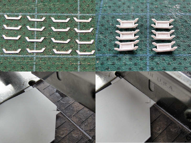
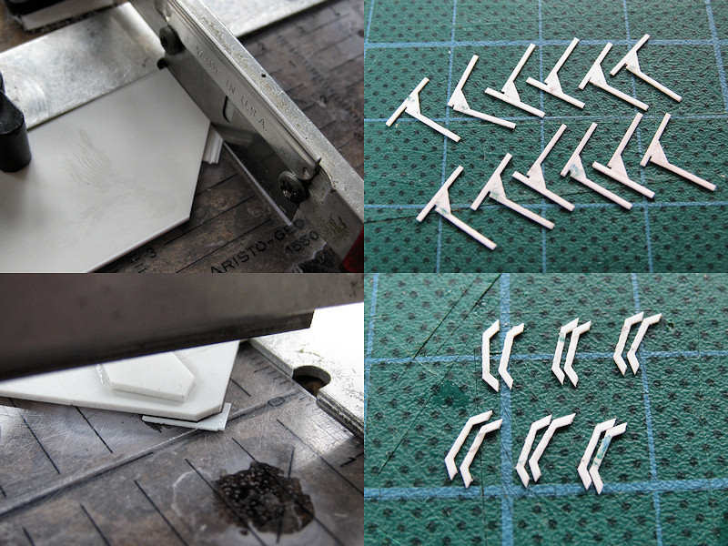
The largest vents are visible here, cut from tube. I added a disk to all rings so that the support of all mushroom vents has the same height; I now need to cut the support to length on the model, paint it, and then add the mushroom vent. This way I know what the height will be before painting the entire ship and I do not have to get the height correct of each vent to what is visible on the photographs after painting . After this disk was placed, a small disk was glued on top of the vent as detail. None of the vents on the photographs have any more detail such as a hand wheel. Too bad, would have looked nice.  The grille of the vent is simulated by an etched part bent into shape and set with superglue. I only had tubes for the largest vents, the two medium sized vents were made from rod with the center punched out as explained here. This was some work with many casualties due to off-center punching, dropping to the floor, misalignment and more dropping to the floor.

I started with the largest vents which I found to be small to begin with, and worked my way down. The smallest vents were really a challenge. I started by cutting up rod in batches of ten. They had their centers punched out by the ten-fold. I decided the smallest vents can probably be put into place prior to painting with little risk showing their white undersides or can be placed on the painted model. So, I put the rod in place. I first slid the rod in (bottom left), dipped the tip into superglue and slid the ring into place. The bottom right shows the result prior to sanding.

These are all the vents; 20 large, 34 medium large, 40 medium small and 58 small, 152 total. At least, 152 are left and dozens more are scattered around in the hobby room. Perhaps casting a few would have been possible, but I didn’t look forward to the prospect of casting several batches of tiny parts with a high failure rate.

Copyright © 2024 On The Slipway

Theme by Anders NorenUp ↑