I bought a small drill press by Proxxon. It’s very cute and not so expensive. I previously used a drill press for drilling in the array of holes of the UP launchers. I tried to do this by hand, even drilling through a photo-etched template I had etched. But, no matter what I did, the results didn’t work out. When using a drill press at work, I found at that for such parts even a 0.05 mm misalignment shows with an array of holes, an error much smaller that I can achieve by hand. After all, the distance between the holes was only 0.1 mm. I didn’t have a good use for a drill press until now as I can always postpone certain jobs of the model, but I felt it was about time to buy one. Proxxon sells several, the one type being twice as expensive as the other and I suppose it has other redeeming features as well.
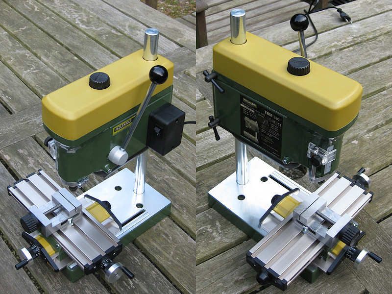
I already have the handheld drill of Proxxon (Micromot 50/E) and a Dremel. Dremel has a much shorter range of tools, mostly hand-held, and they always feel more like toys than tools. Being taken over by Bosch apparently didn’t really help. Their collets are flimsy and flexible, while Proxxon has proper steel collets. Sure, Proxxon is rather childish compared to the tools in the workshop, but those tools are quite expensive for the limited use on my workbench. On most Dutch websites, the Proxxon tools are even sold as ‘modelbuilding’ tools only. But it’s the extra’s of Proxxon that made me buy one. They have a very cheap compound table (27100) and (more importantly) a precision machine vice (24260) for ‘intricate and accurate working’. It’s orthogonal and flat and can hold very thin strips. This is what I intend to use it for, as most other vices are not so flat and orthogonal. Industrial vices that are flat cost far more than the entire combination I just purchased so it sounds like rather a good deal.
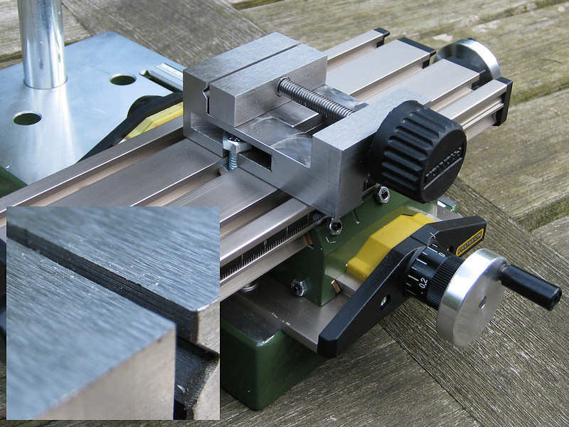
The drill press itself is the Proxxon TBM 220 (28128), “competent drilling of micro holes down to even 1/64″ (0.5 mm)”. What? That crude? The drill press uses the Micromot collet system, so that’s a range of six steel collets, the smallest being 1.0 mm and not being able to fix a very small drill at all. I thought I was really clever as my hand-held drill can remove the Micromot adapter and use a normal chuck. Image my surprise that the hand-held tools use a different size of drill-chuck. You can buy the “original German Röhm chuck for drill bits up to 1/4″ (6 mm)” but that one starts (!) at 0.5 mm. Hmm, I wonder who decided using two systems was a great idea.The other thing that was unnerving was the enormous slack in the compound table. Good enough for my modeling and admittedly: it is reasonably cheap at nearly 10% of the cost of a real contour table. I tightened it a bit, but it’s not really machining accuracy. Also, the adjusting screws are tightened themselves by M5 nuts. I don’t know about you, but I have several complete series of wrenches that all start at M6 so I had to use pliers. The first scratch in the paint was present before trying out the drill itself. I never understand why machines are not fitted with one size of screw or bolt but a mix of different sizes of screws and bolts using the slotted (ack!), Phillips, Hex socket and torque screws types ( I can spot 5 types just on the stand of the drill press). Why not use one size of hex slot? Also, the stroke of 30 mm of the drill press is quite small but I knew that when I ordered it. But what I should be saying is that the combination is actually nice value for money at three-hundred Euros. At least I think so, and the entire drill press has a small footprint which also comes in handy on a perpetually crowded modeling table.
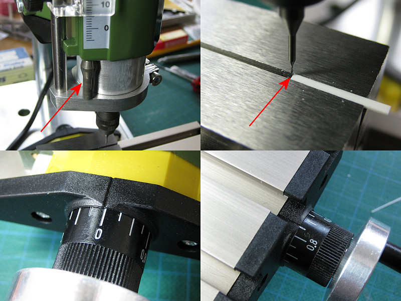
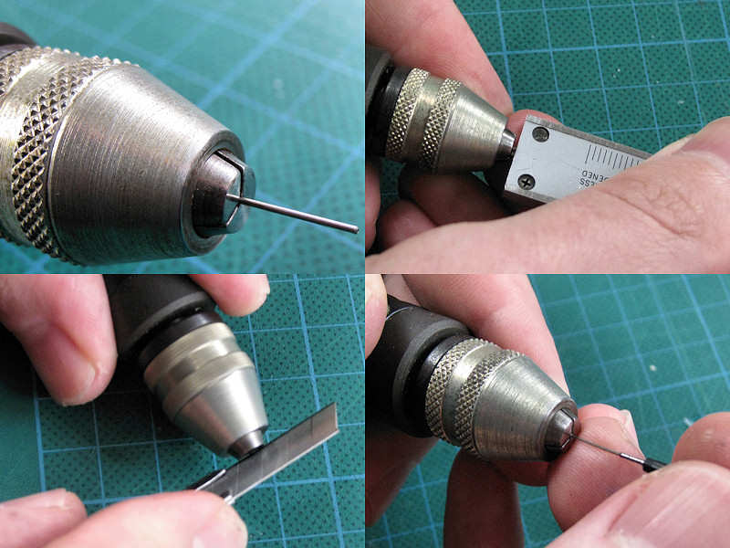
Upon starting to use it, I immediately found another severe deficiency of the Proxxon drill press: you cannot fix it at a vertically-fixed position. I solved this by throwing in a collet I didn’t use at the time to keep the drill in its downward position, shown top left. I then inserted a strip in the vice touching the drill and called that position ‘zero’, corrected for the radius of the drill bit. Ah, the macro-pic bottom left shows it’s not exactly centered.
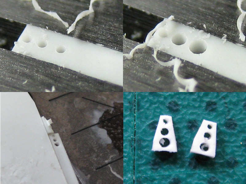
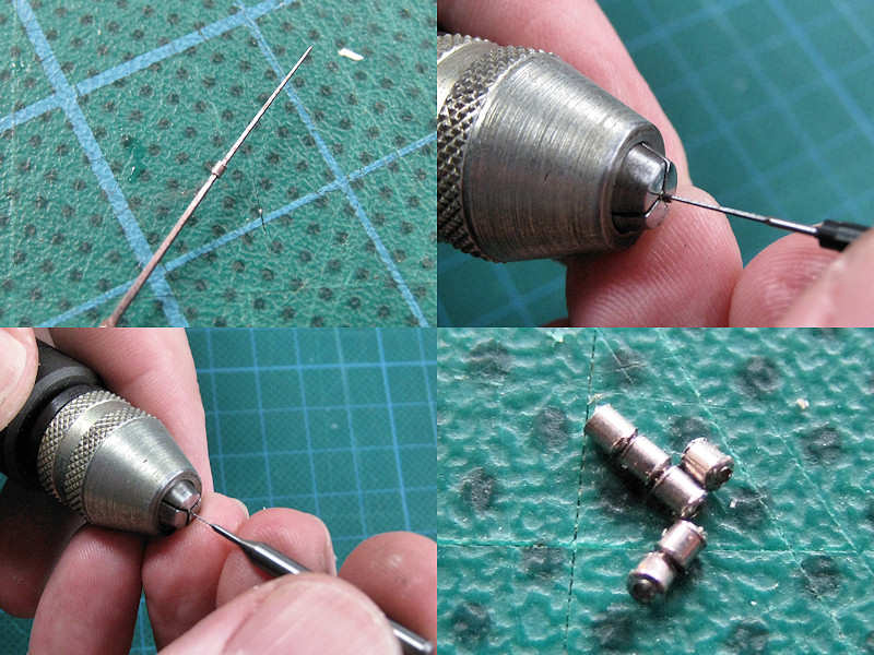
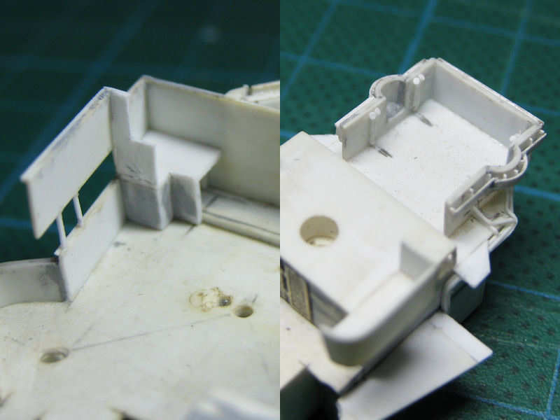
I don’t have that many quality drills laying around as all but the most flexible miniature drills break quite often when using my hand-held pin vice. I found a source of cheap 0.3 mm drills (a second-hand seller, twenty times cheaper than the shop price). I pre-drilled in all the required holes with those drills for this particular part and finished them off using other diameters (0.4 and 0.5 mm) The parts (prior to sanding as my chopper isn’t that consistent) look fine and will be put to good use.