
Page 7 of 29

Shelterdeck, part I
Hood modellers were recently confronted with two changes in HMS Hood’s appearance. The first one related to the underwater hull; it was most likely never red, but either slate or black. Research is ongoing and I expect the painting guide of HMS Hood on the official website to be updated soon. Second, we had a discussion on the application of Corticine on board HMS Hood (Corticine is often spelled Corticene in admiralty records). Corticine is a linoleum-like substance, a ground cork and caoutchouc or India rubber mixture, that was added to the decks as an anti-slip measure. On the exterior it was usually applied for bridge deck areas where the crew was expected to stand for prolonged durations. Dave Weldon, who studied HMS Hood a fair bit longer than I did, has Corticine on the shelterdeck of his Hood model the large open area around the bridge and funnels. I had noticed that this area had a rectangular gridded pattern on the deck, but never made the connection this could be corticine. After all, these lines follow the plate pattern of the deck and no appreciable contrast change with the rest of the ship is observed. But the gridded pattern is a strip pattern, and upon closer inspection of photographs and based the logs corticine, as well as an a lengthy discussion with the Hood Association, we came to the conclusion that corticine was indeed present. The pattern is estimated to have a 6ft x 12ft spacing, laid symmetrically with regard tot he ship centreline and starting on the expansion joint that runs through the emplacement of the forward pompoms.
The ship logs also indicate that Semtex was added in 1937. Semtex is also an anti-slip material, trowelled on and confined at the edges by small headings of steel welding on deck. It was a rough material said to wear down shoes quickly. It can appear in several colours, reported to be light grey, tan, blue, green, or red brown, with only tan and light gray as an early WWII option, depending on the manufacturer (They remain unspecified in the logs of HMS Hood). The location of the Semtex is indicated near the emplacements of the 4inch high-angle guns. When we look a bit closer on all the images of the deck it is clear that the grid pattern is only partially present, indicative of both Semtex and Corticine regions; many of these pictures were taken in either 1940 or 1941. So, with some certainly we can now say that the entire shelter deck is either wood, Corticine, or Semtex; there is no spot of dark deck grey to be seen (not counting on top of the various deck structures).
With this new information I went to work, adding the lines in stretched sprue; this material is cheap to make, and can be easily glued with the sprue pulled taut on the deck. The difficult is aligning all these lines with so many obstructions already on the deck, so I had to mark all positions carefully and use tape to fixed the lines fore adding glue. Calipers were often used to get the distances correct. Some lines were not entirely satisfactory and were replaced. The far foredeck was especially tricky but worked out very well. The the pompom area was given a corticine treatment as well, but that was later shown to be incorrect.
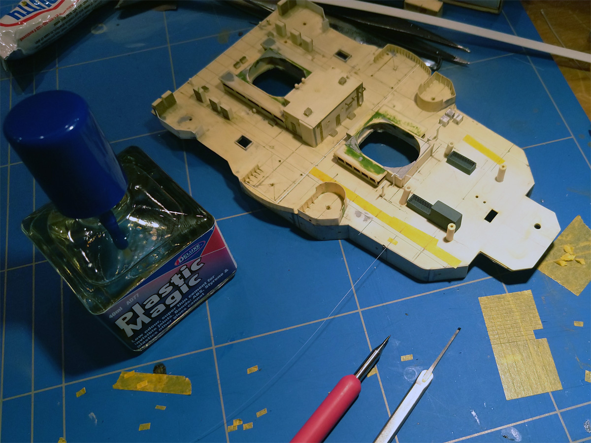
I recently picked up a bottle of Plastic Magic via a tip on the Britmodeler forum; it’s a very thin liquid cement that you can apply by a fine brush, similar to Tamiya’s Extra thin cement. I always used Uhu’s (with the needle dispenser) or sometimes glued using thinners. This new glue is much easier to use, and I wonder why I didn’t pick up these thin glues earlier. This is a small experiment with a 0.13×0.20mm strip that could be glued very easily. Note that there are three ammo lockers forward of the UP launch emplacements; these are on many drawings but not on any photograph and were removed, causing a lot of damage to the deck,
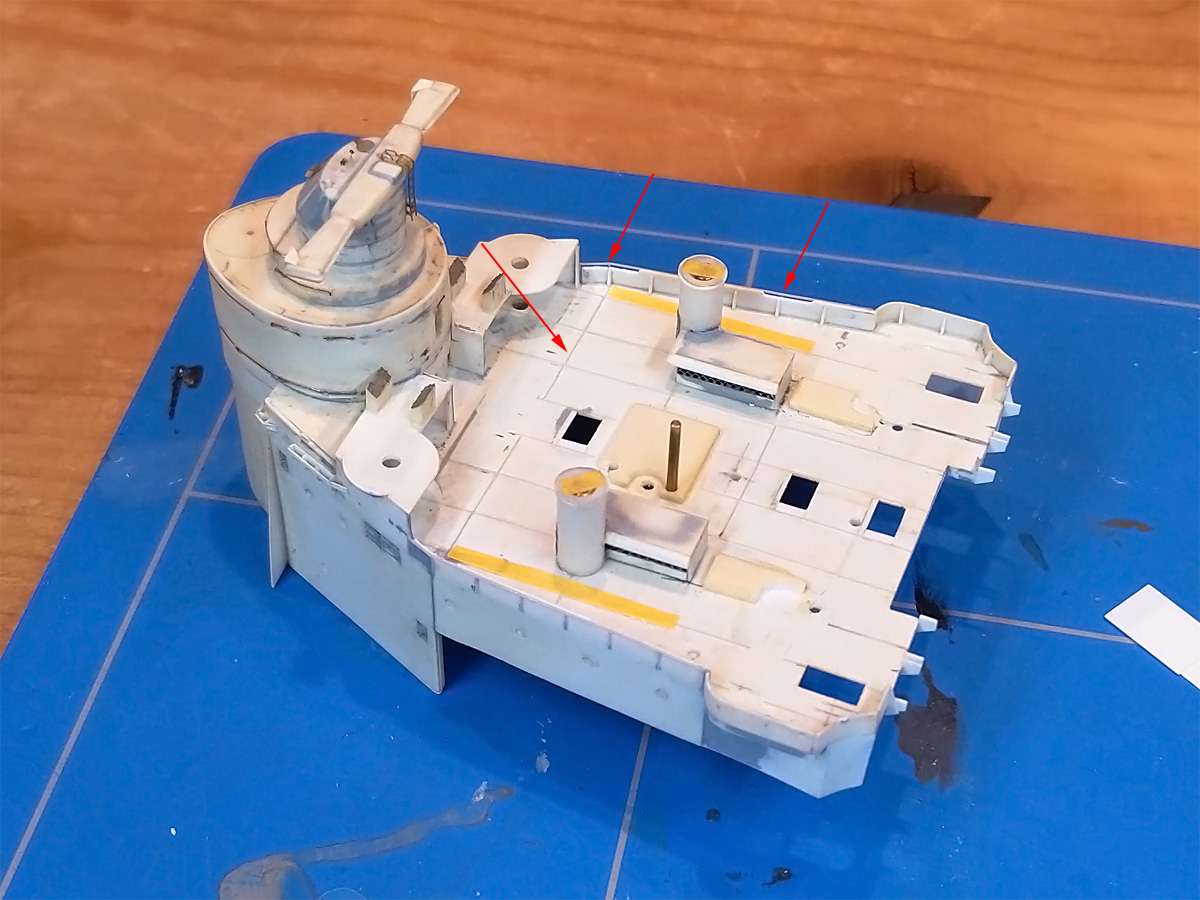
The bridge deck was also covered with styrene, so here’s a shot of the strips in process; this part isn’t done yet. While I was at it, I carved out a small step in the splinter shielding where the saluting guns used to be present.
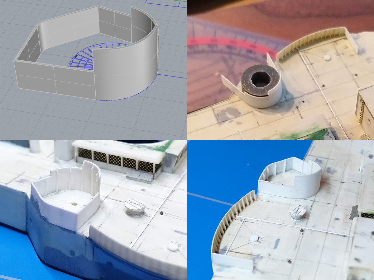
While adding the strips I noticed that all the parts on the model aligned with the 12x6ft corticine strip pattern except the forward UP splinter shielding. Plus a new pic showed I didn’t have the outline exactly right. I made a small model in Rhino first. I made a small plug on the lathe to help positioning the shield during gluing. Small stiffeners were added, as well as a small aerial trunk built from discs and Magic Sculp.
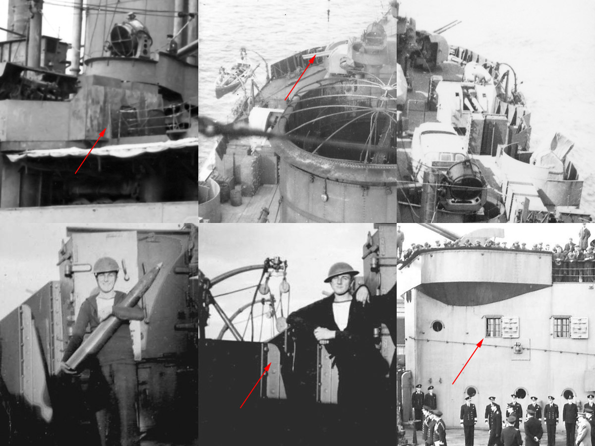
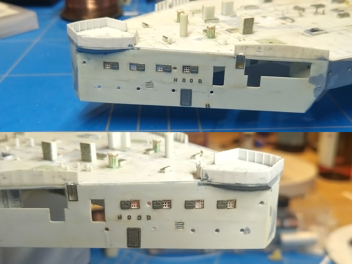
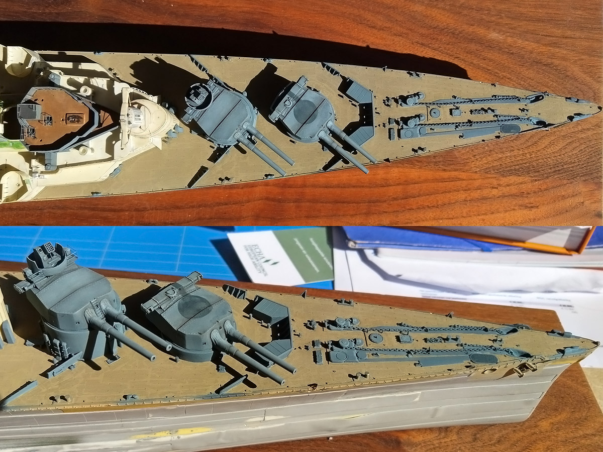
The rest of the splinter shields were only partially finished, many missing the stiffeners in the back. The two pics on the lower row show these strips are a strip and a small triangular plate. Also noticed a small storage container on the after most shield , presumably to store items required for the 4in guns. The bottom-right image shows the windows to the Admiral’s day cabin (with the dining cabin forward, also with two windows per side) that are shown a bit below.
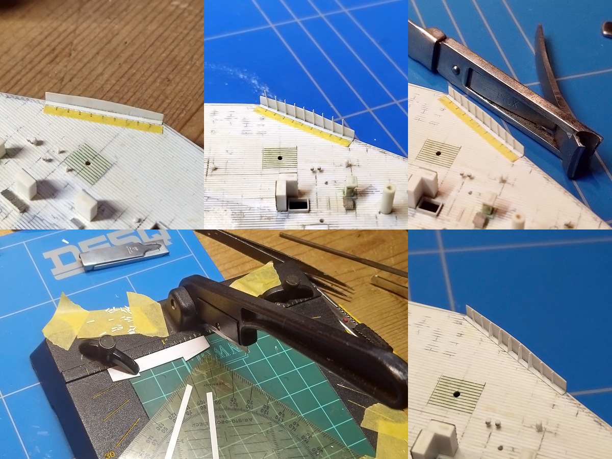
The strips were added by first adding smalls trip of masking tape with the right spacing. Small strips of 0.13mm were added next. When the glue had set these were beheaded using my clipper. A series of support triangles was added next. The photographs show that each triangle is not the same height as the splintershield, so I rounded that the height to the first half foot. The bottom left shows the copper at work, with a series of strips of the correct width. A small styrene template is first used to cut the strip at an angle and then chop it to size.
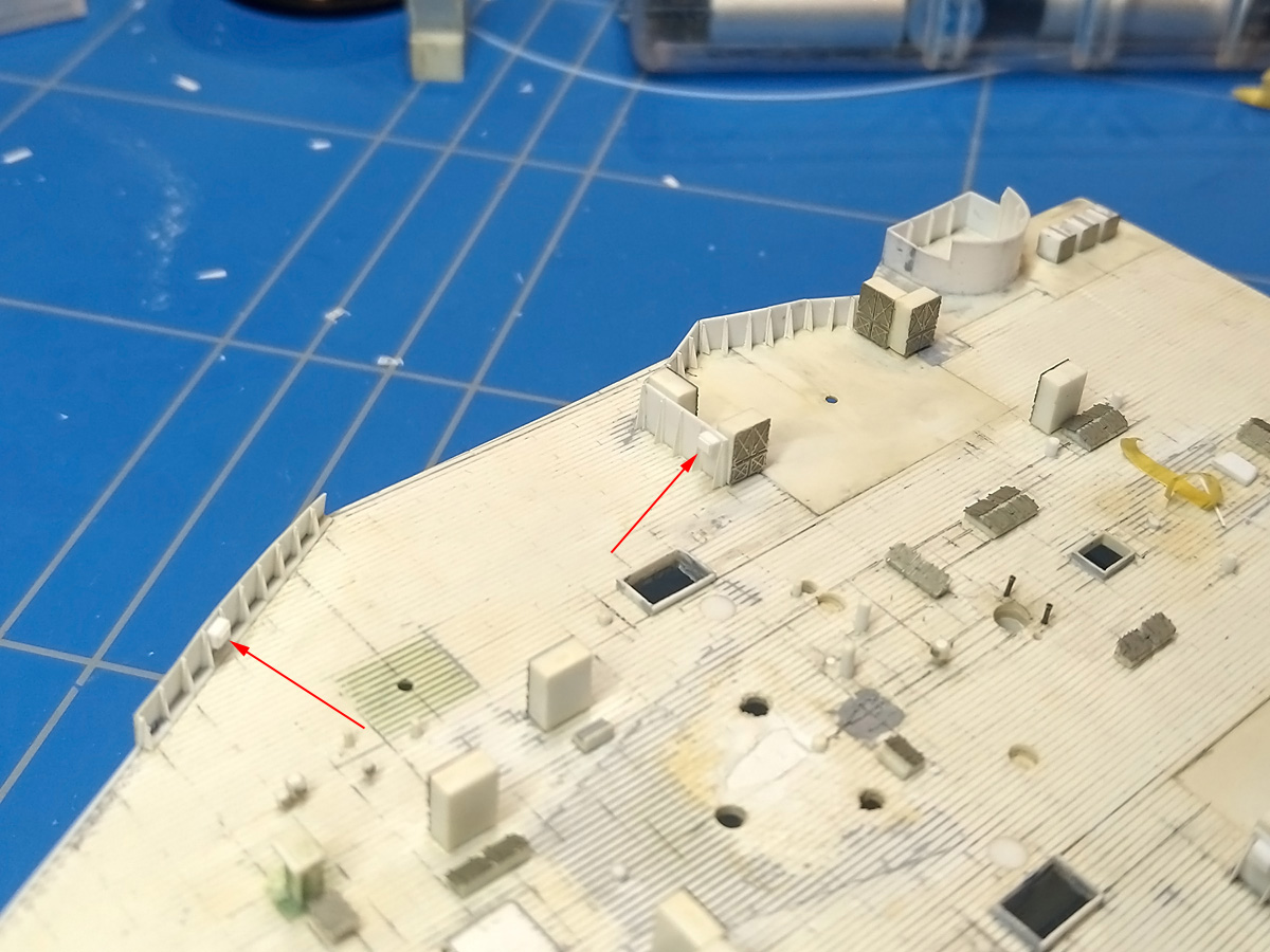
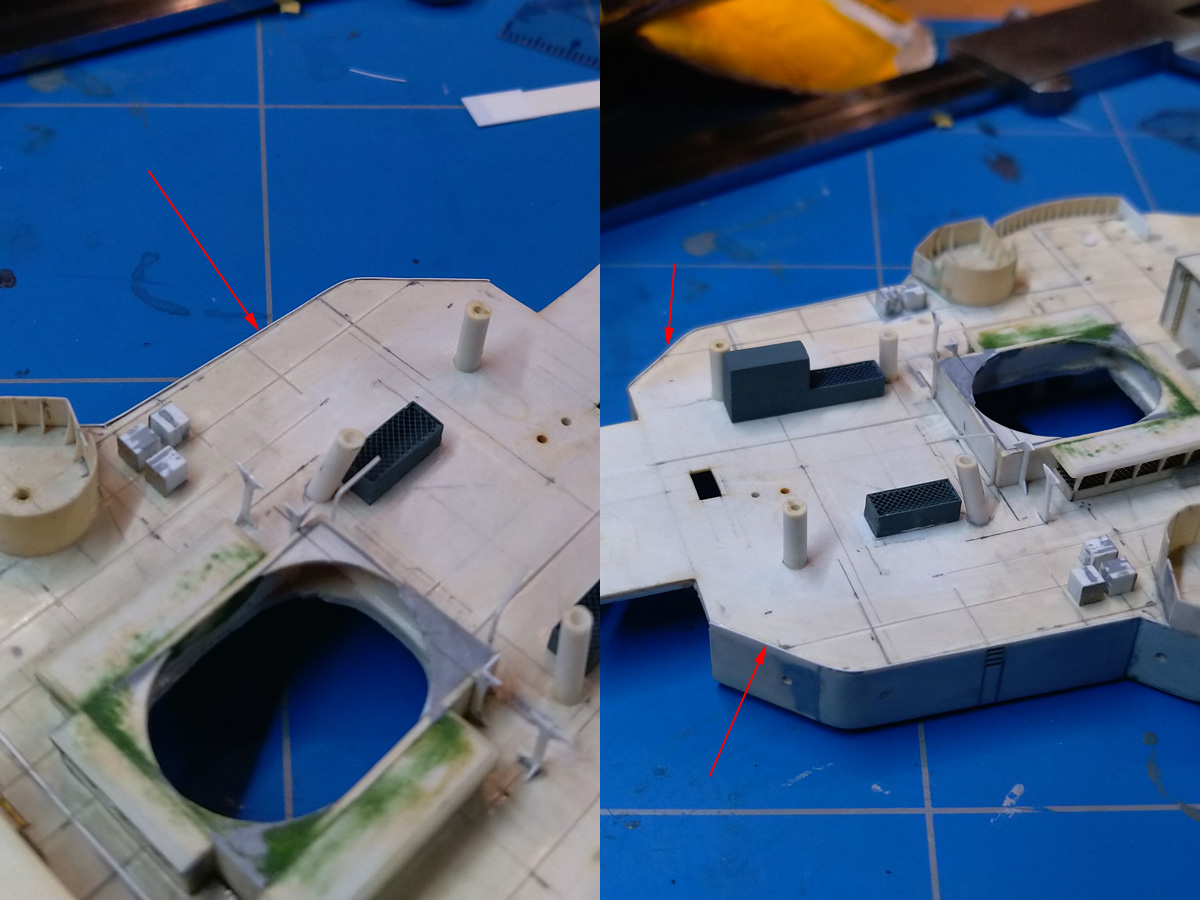
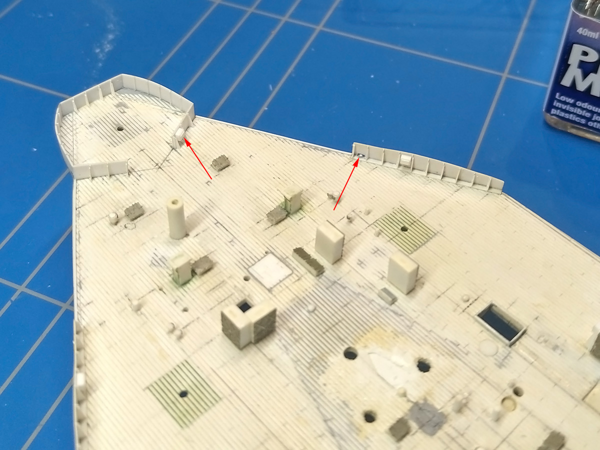
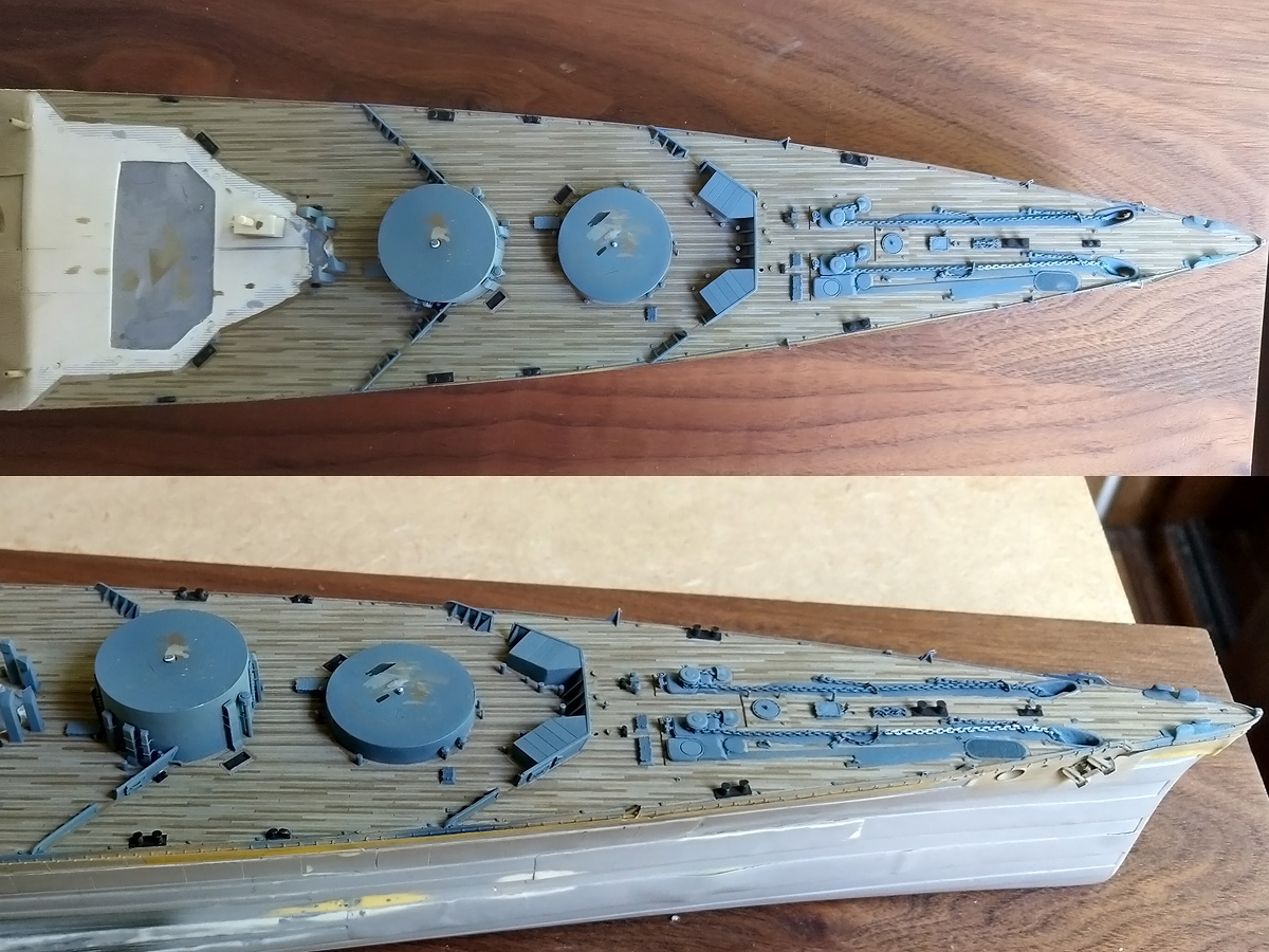
Results of the shelterdeck as it is now; the arrows indicate the location of the lockers, both confirmed in photographs.
The smaller shield as a smaller opening where a small hand wheel was present to lower some shutter. Although I have no good pics of the aft 4in gun emplacement, I added the locker as random detail.
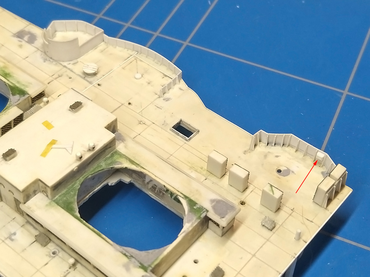
I added another random locker to the forward 4in gun emplacement, and also replaced the splinter shielding around the pompom in the new style.
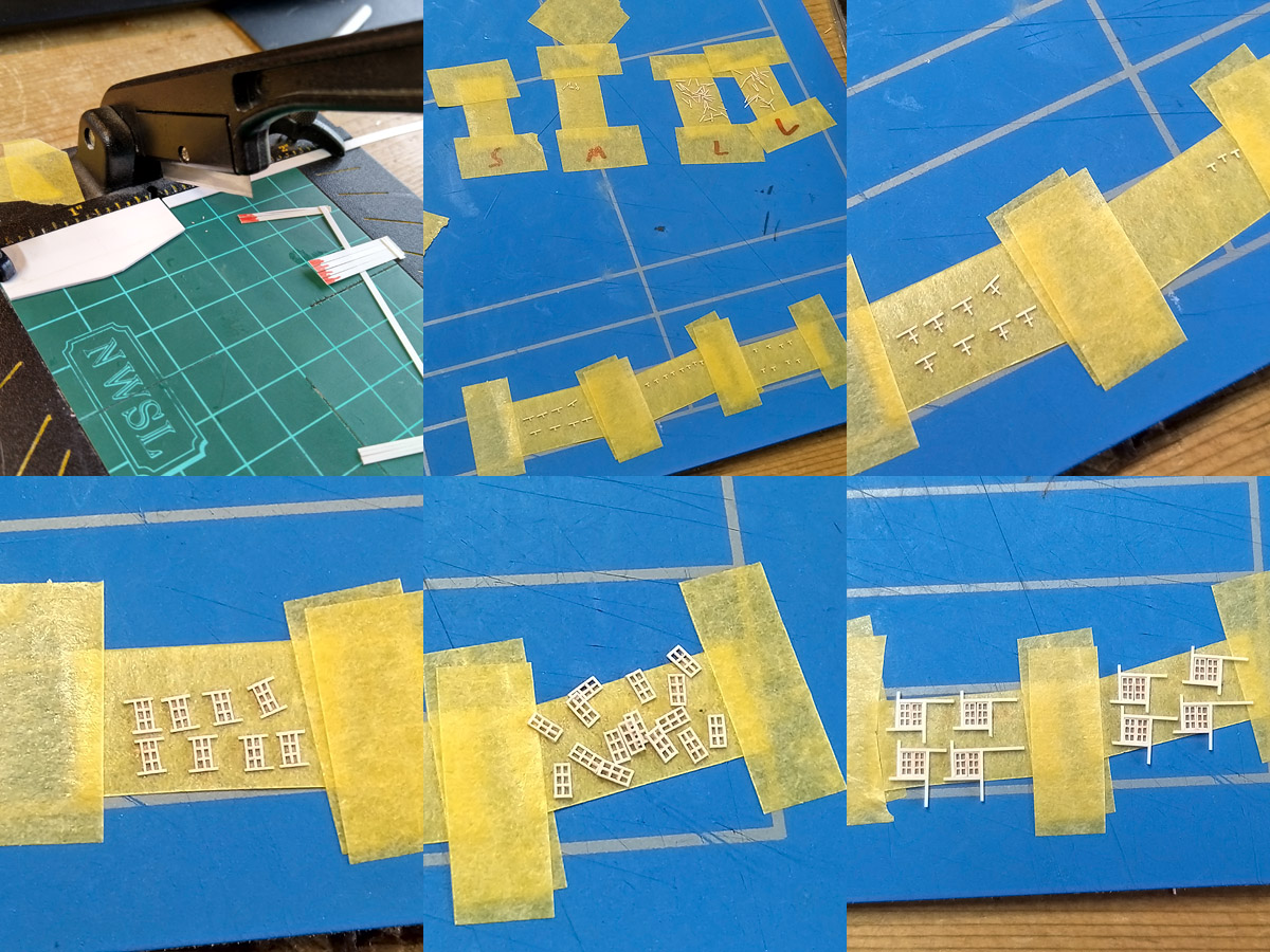
While I was at it I decided to do another experiment with my new glue and built a set of windows for the admiral’s day & dining cabins. The openings are only 2×2 mm, so I needed very thin strips. I used a stop that was touching the blade, giving an about 0.15mm thin strip. This means I’m cutting of slices half the strip thickness. I added a bit of colour to not worry too much which side is “down”. I made a small assembly line using tape; not entirely useless as the small and medium strips were about the same size and initially parts ended up mixed making for bad windows. Building these small parts in series also ensures that the glue can set between each step. A total of 8 windows of 22 parts were built
And the result; I had to do some carving to the back plate which was quite unnerving, but nothing went wrong! The rest of the part is in line for cleaning up.
Painting the deck, Part II
A small update of some work that was done earlier and then stalled a bit. The fore deck was next in line for painting. Unfortunately I had a minor disaster with a coat of Humbrol H72 giving rough spots. After brushing the model with alcohol I lightly sanded the deck and removed the grainy surface where I could using pieces of sanding paper glued to toothpicks; etched parts could be scraped clean. Many details are soldered or glued firmly, but the vents around the barbettes are most fragile and took a bit more time. It went well enough, but I was otherwise very much not pleased loosing a day or two that could have been spent painting. Not sure if it insufficient stirring or thinning but it was probably my fault somewhere along the line. Learn by failure I suppose. The result is still not too bad but macro shots will show the bad finish in some areas. Perhaps one of the reasons I dread painting; some errors are very difficult to correct.
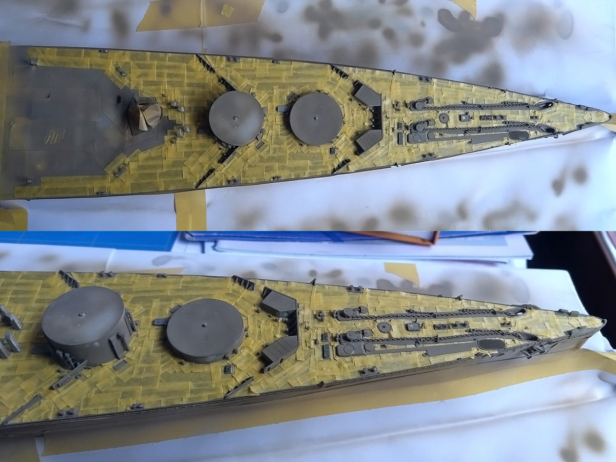
The entire deck was masked after a layer of primer, corrections, and a couple of coats of Humbrol H72, rough-spot corrections and a barrel of Whisky. There’s a lot of detail to work around, so this takes many wee bits of tape. As the deck will be painted by hand it doesn’t have to be too exact.
The rest was sprayed with two coats of my AP507A/B mixture (Humbrol 34 White, 77 Navy Blue and 140 Gull Grey). I initially stored some batches on paint in Badger jars and most of this dried in the jar; I bought a stash of empty tins at https://www.phoenix-paints.co.uk/, including some 125ml tins for storage. Meanwhile, the new Humbrol colours I ordered do not mix to the same colour I had; too blue. With some black and some drops of red the colour might be used as a base. Fortunately I have a a few tins of my old paint lying around, more that enough to finish the model but if they spoil too more Whisky is in order. Note that the sandy layer of H72 on the deck shows patterns of masking, as a final insult to my painting troubles, but that didn’t worry me at all.
Then it was a matter of painting in all the plank work again, using the same recipe of Humbrol H72 Khaki Drill, H72+H110 Natural Wood, H72 + white and pure H187 Sand (a discontinued colour). The deck edge details were touched up in the base colour and bollards and steam winch positions in black. The colour of the chains is typically hull colour but one shot from 1940 shots the starboard chain to be a bit lighter, so I copied that to add some variation, in Sovereign Hobby’s AP507C.
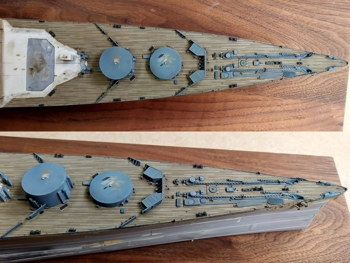
Three washes of van Dyk brown followed. I used Winsor & Newton’s Sansodor as a solvent that dries very slowly, allowing for some touching up and clearing excess wash from the deck with a wet brush (when the wash is starting to set). The contrast between planks is perhaps too pronounced, but it’s tricky to strike a balance between having contrast differences while at the same time having the deck appear as one colour. The contrast is a bit more than on the quarterdeck with the darkest brown being more brown. Probably the universe telling me to paint as much as possible in a single pass.
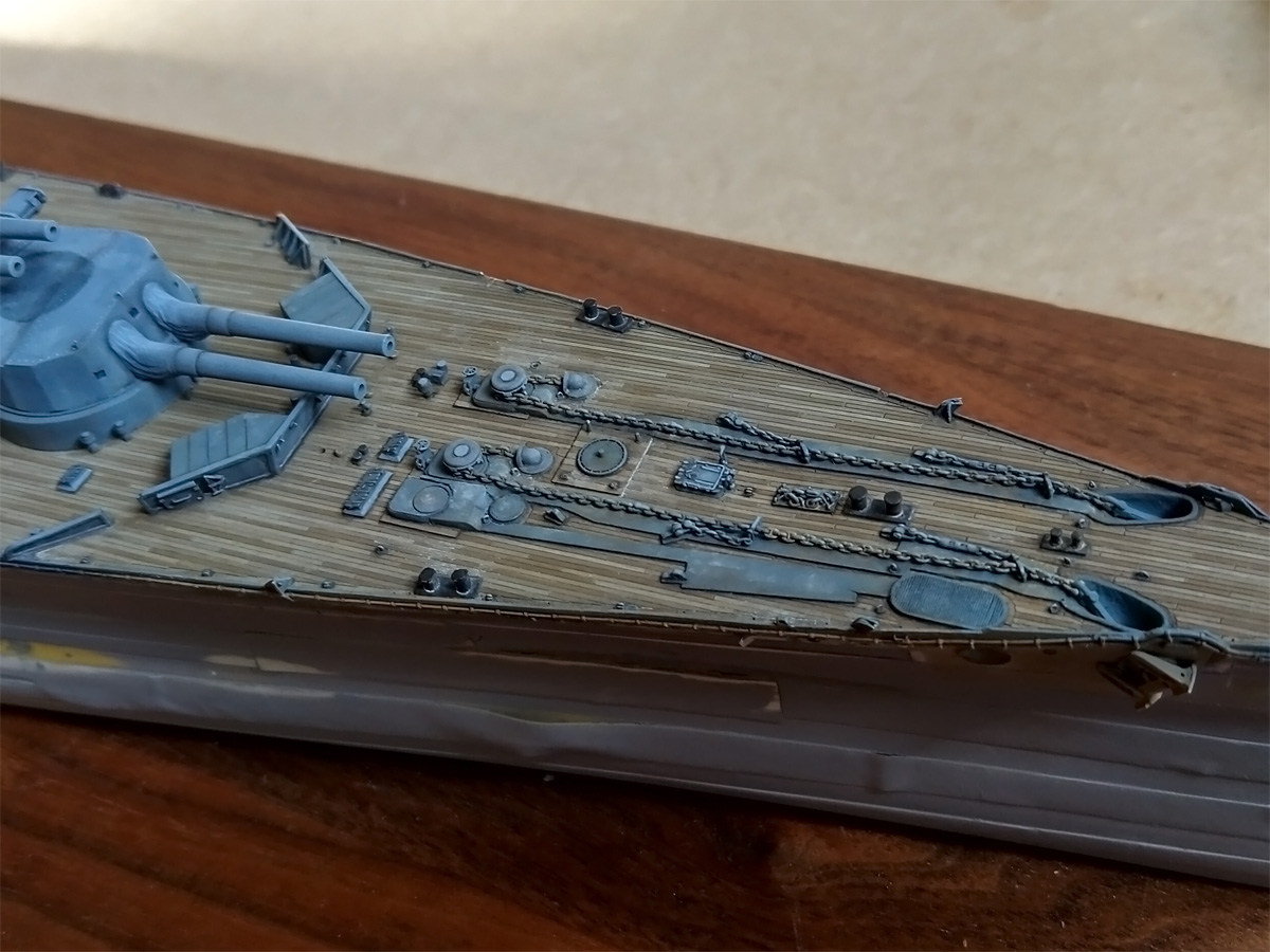
The background receives a dot filter first, that is random dots of colour (red, blue, brown, yellow) applied to the base surface spread out by a wet brush. The next stage followed the approach as described by Marijn van Gils in his stellar book “Lexington’s final battle”; the main idea for enhancing contrast not to add a (pin) wash plus a drybrush run, but adding shadows and highlights by a fine brush where needed without affecting the base layer (much). T
he first step in increasing contrast was adding shadow lines using a very fine #000 brush and a black/raw umber mixture plus a #1 brush standing by for corrections. This gives a bit more contrast than a pin wash but also requires more time and control. At first these lines appear to be too dark, but after drying the results become less pronounced, so you really need to try it a few times and overdo it just enough that the results in the end are fine. It’s particularly well visible at the edges of the deck or top to the capstans. The second step is adding highlights, starting from base colour for correction work where required)a nd adding more H140 Gull Grey the smaller the details get. This really makes all details pop up, especially for the etched details. This phase was followed by a layer of white spots and smears representing salt deposits of Humbrol Radome Tan; I tried it first on a separate part of the model to see how this would work out and the result is: actually quite good. The light part of the anchor chain was (reversed) drybrushed with the base colour to simulate wear of the light coating; the entire chain received a subtle wash with Humbrol Leather for a combination of rust and sediment. An additional layer with adding darker spots and deposits will follow later. The shadow & highlight stages takes time and some regions are difficult to reach, especially the breakwater where adding these long lines is tricky. Mushrooms and winches were painted separately; hose reels are still on the to-do list. Some minor work will follow to finish this bit but I got distracted be the boat deck…
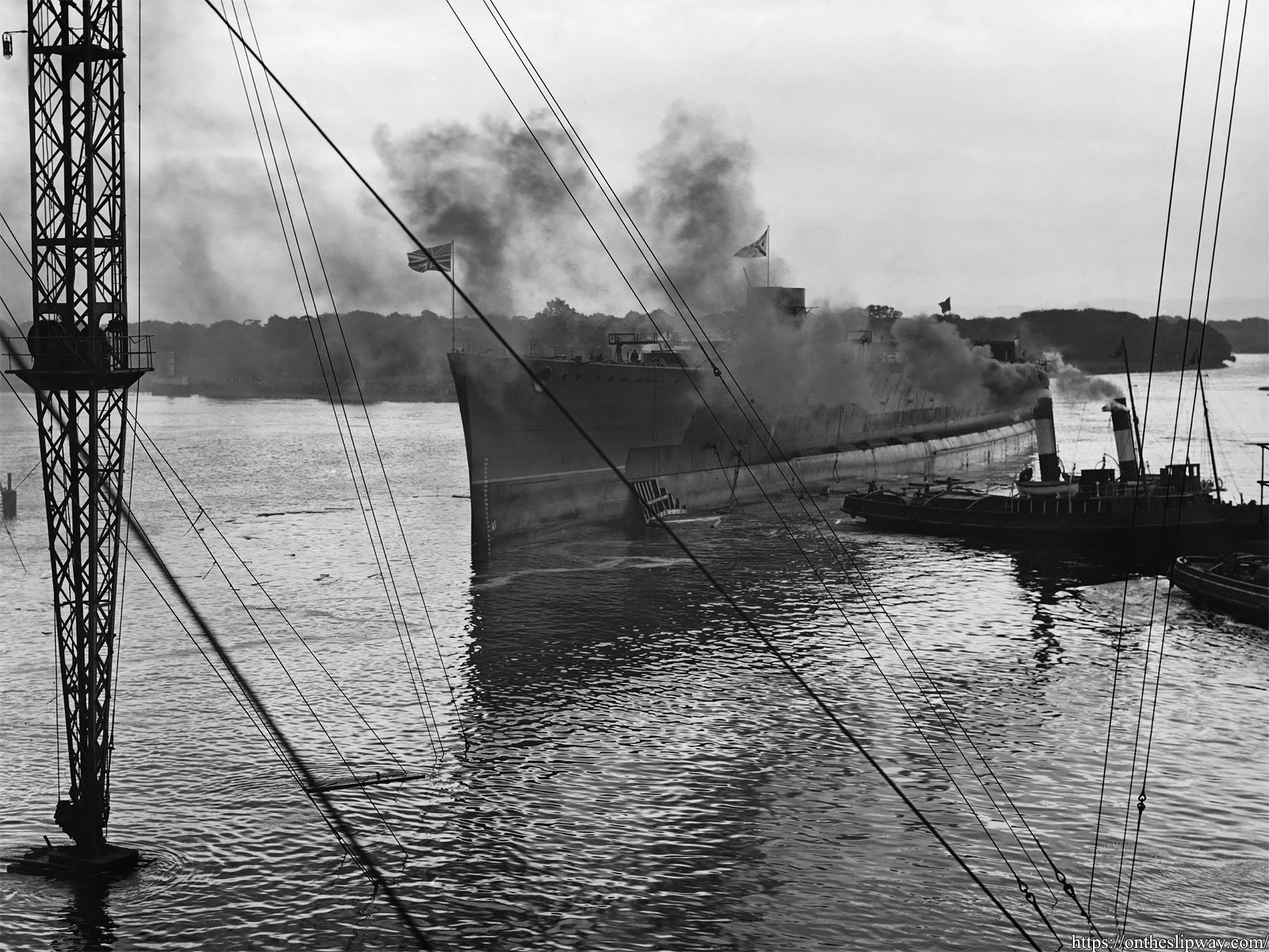
The launch of HMS Hood
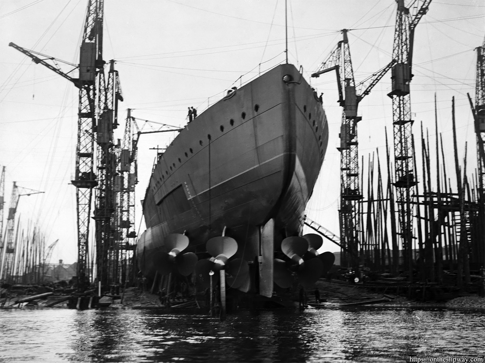
HMS Hood was launched on the 22nd of August 1918 at John Brown & Co shipyard. These images were originally owned by Sir Thomas Bell, the MD of John Brown & Co and I was fortunate to obtain them. Some of these images—and quite a few others—can also be found in Ian Johnston’s highly recommended “Clydebank Battlecruisers”, (2011) and “A Shipyard at War” ( 2014), Seaforth Publishing.
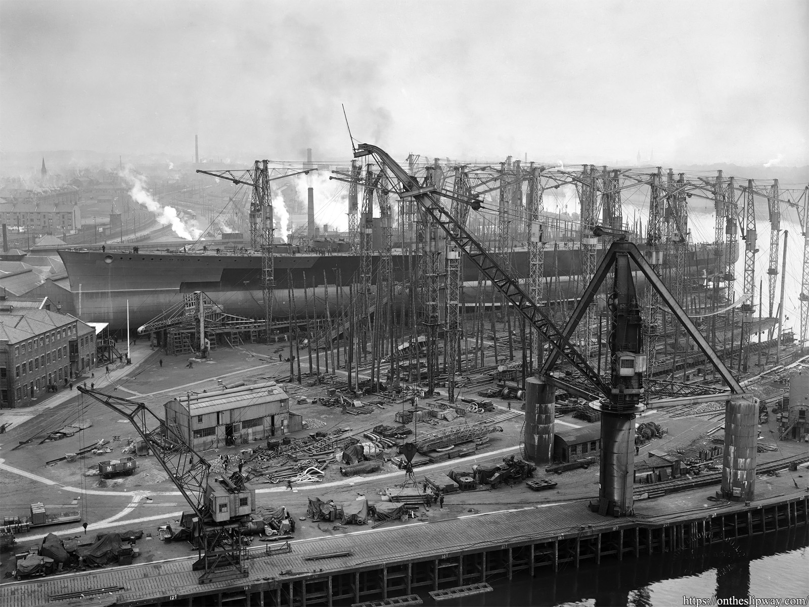
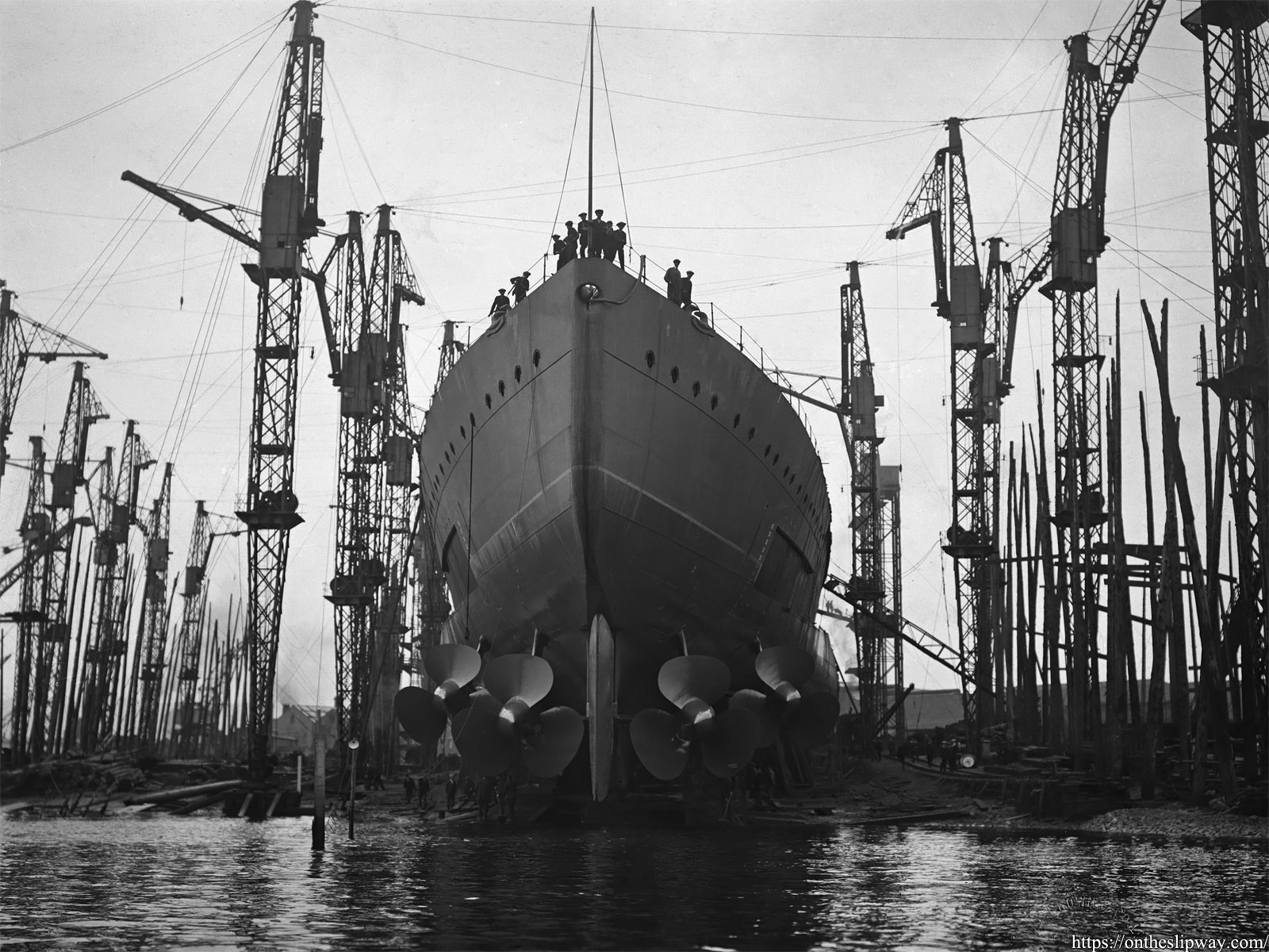
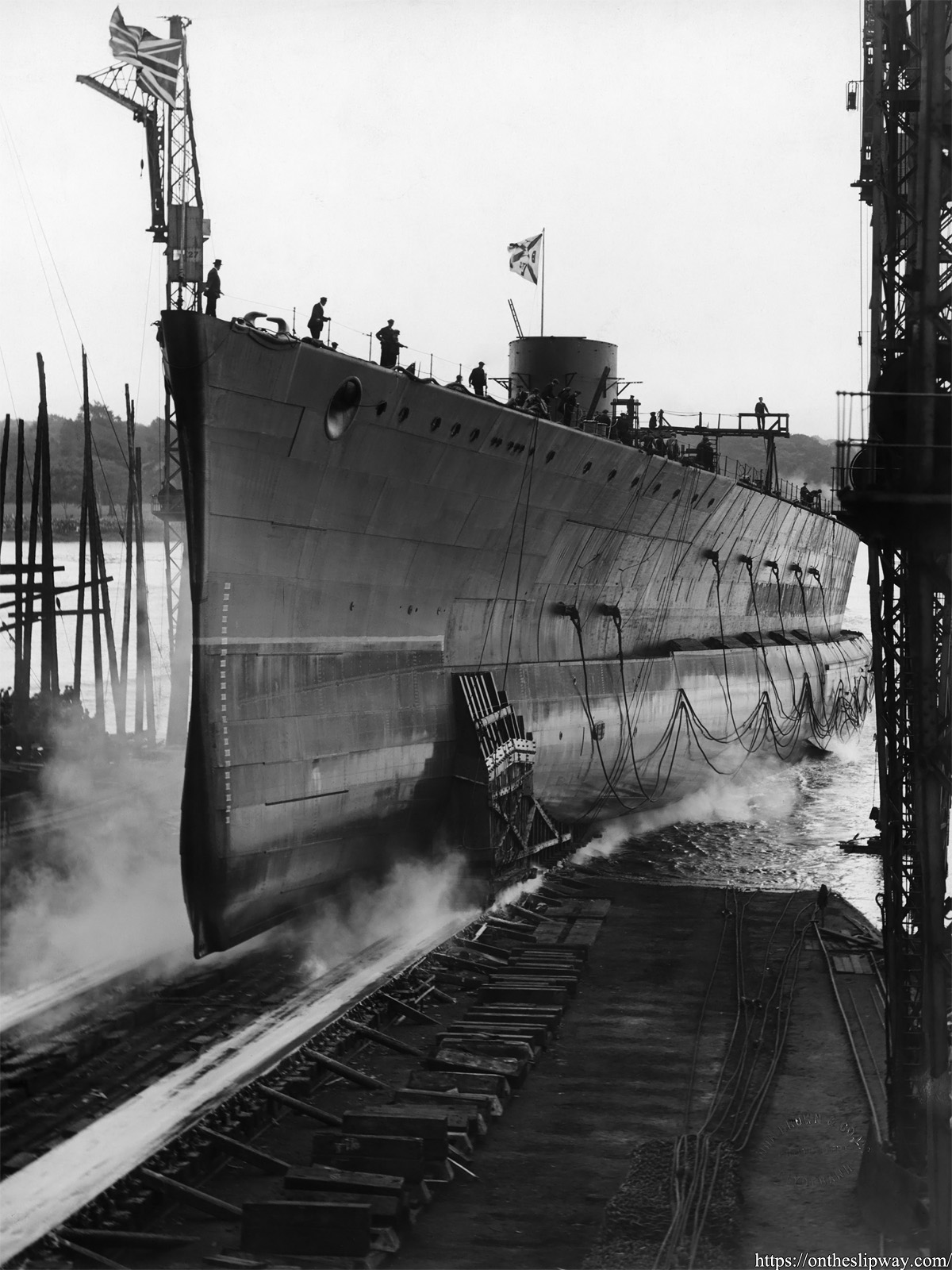
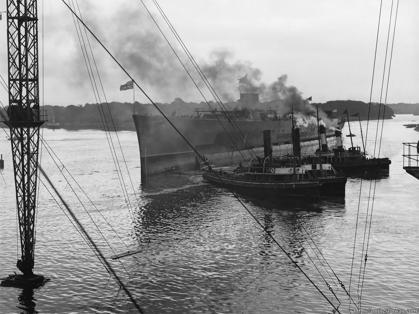
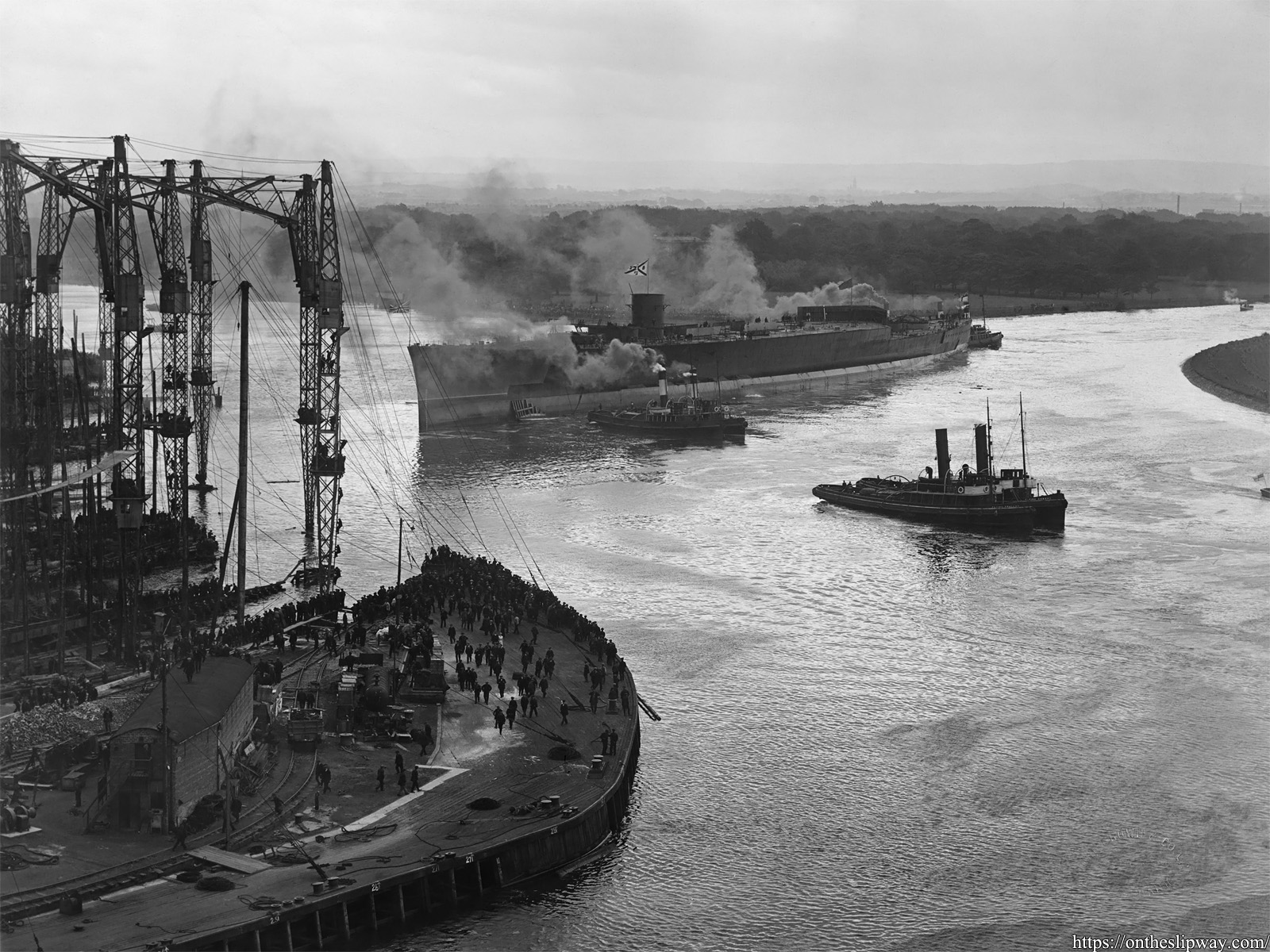
A wonderful shot of HMS Hood’s hull on No 3 slip (Johnston, 2011). This is my favourite image, showing the chains used to stop the hull during launch (more clearly visible in the following image bottom right), the large 150 ton derrick crane in the foreground, the yard’s shops and stores, a forest of cranes, the buildings and train yard, church towers at right.
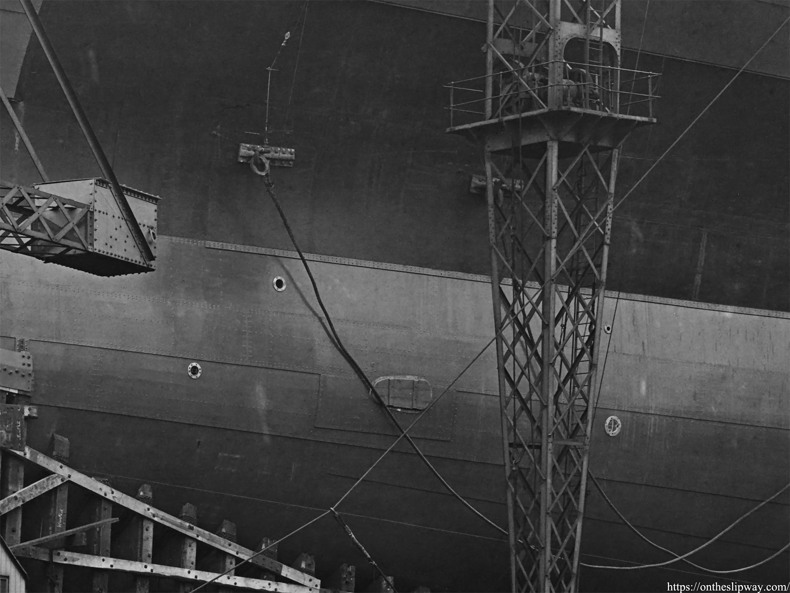
This close-up shows the port side underwater torpedo tube; the starboard tube on the opposite side was slightly more upstream. The openings in the hull upstream and downstream of the torpedo tube are seacock openings with discharge openings above them.
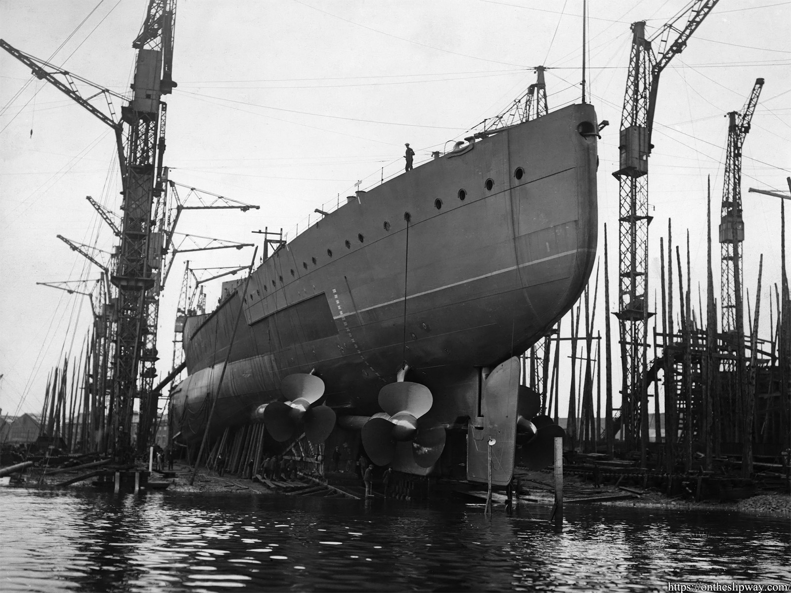
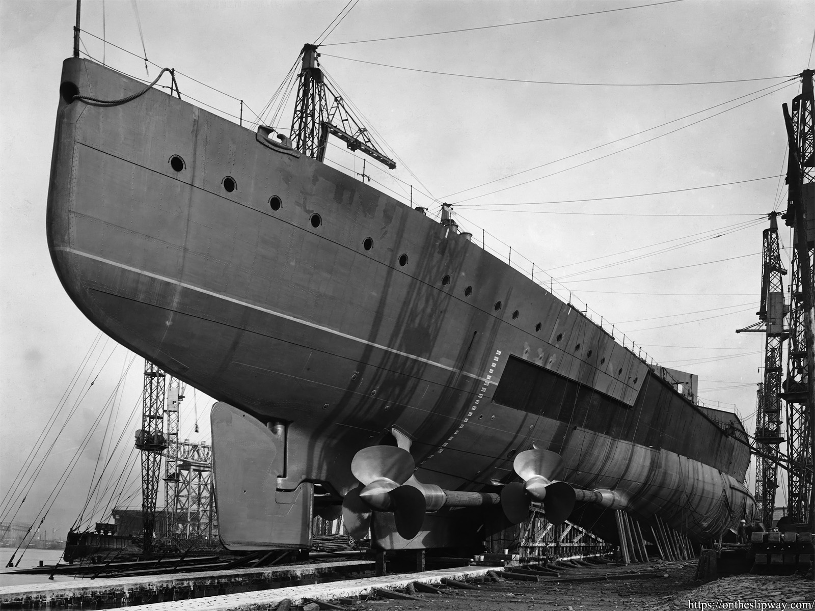
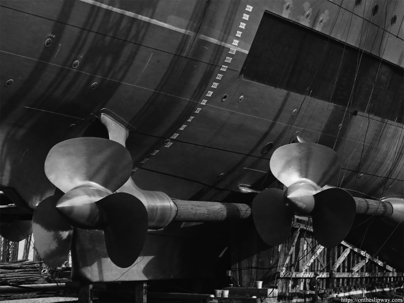
As my work focuses mainly on propeller design a close-up is in order.
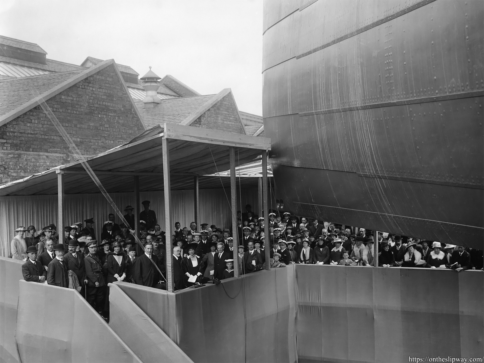
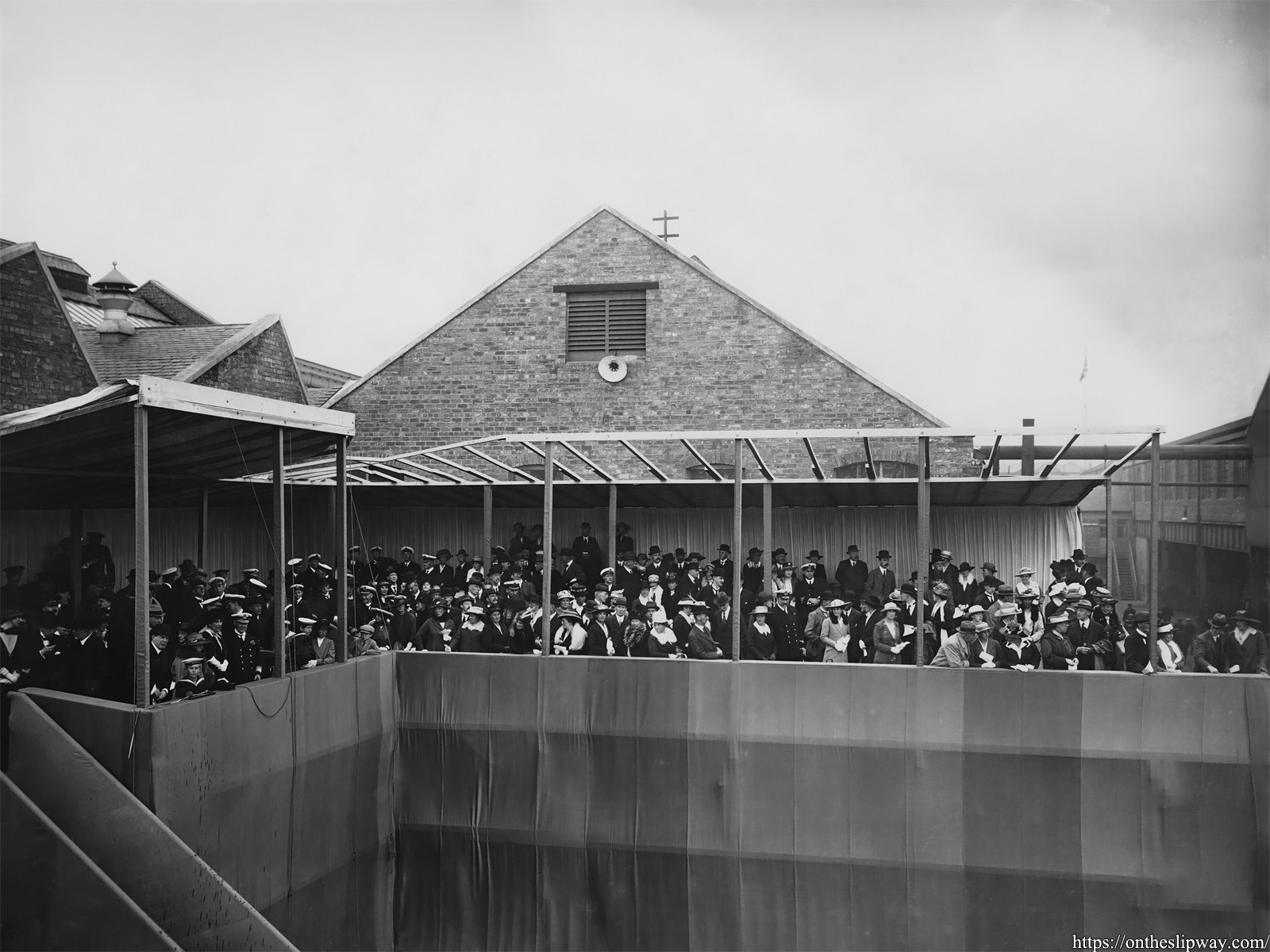
The crowd after the launch, with traces of Champagne visible on the ramp at left.
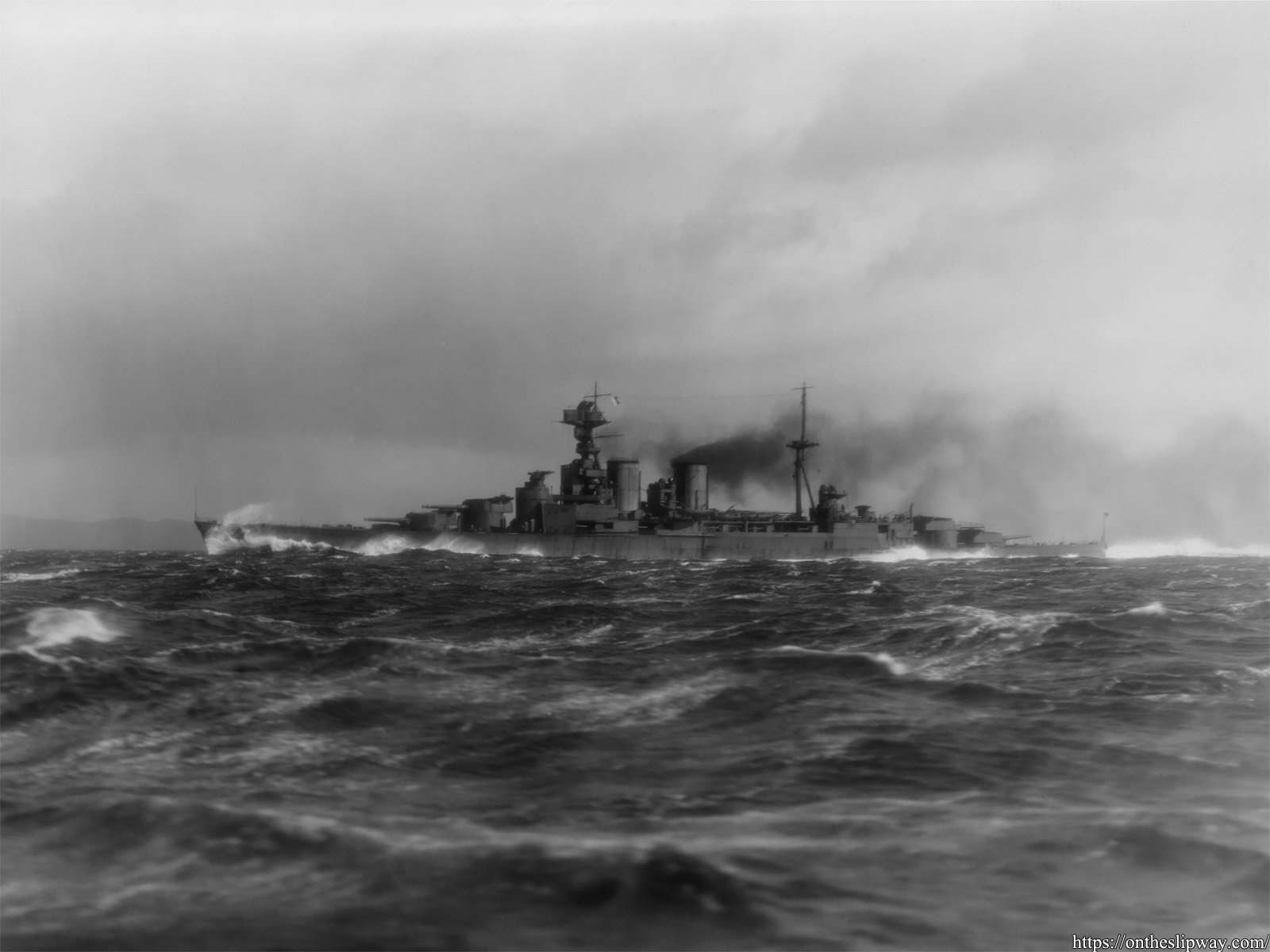
HMS Hood on the 18th of March 1920 running her speed trials.