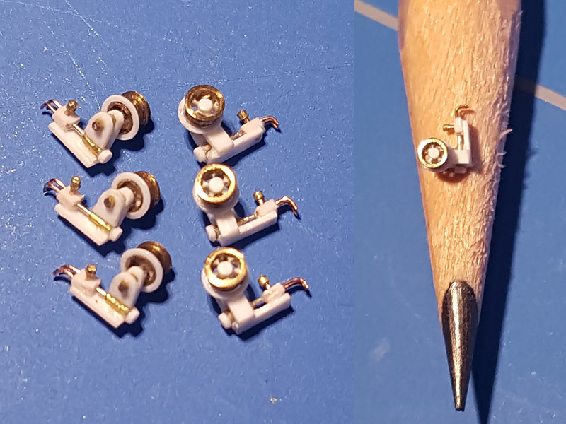
I hadn’t used the lathe for some time so it took a whole afternoon until I could reliably produce parts again, if it weren’t for a small offset on my drill fixed in the tailstock of my Proxxon PD230/E. This offset has always been present and trying other drill chucks didn’t solve my problem. I took a few chucks to work and they measured an offset in the Morse Cone I of about 2 to 3 hundreds of a mm, just enough to be troublesome with thin-walled parts I was trying to make (20″ signalling projector). I ordered a ER-11 collet chuck with a MC1 fitting that is supposed to fit in the tailstock, but it doesn’t; the Proxxon PD230/E tailstock has a much shorter run.
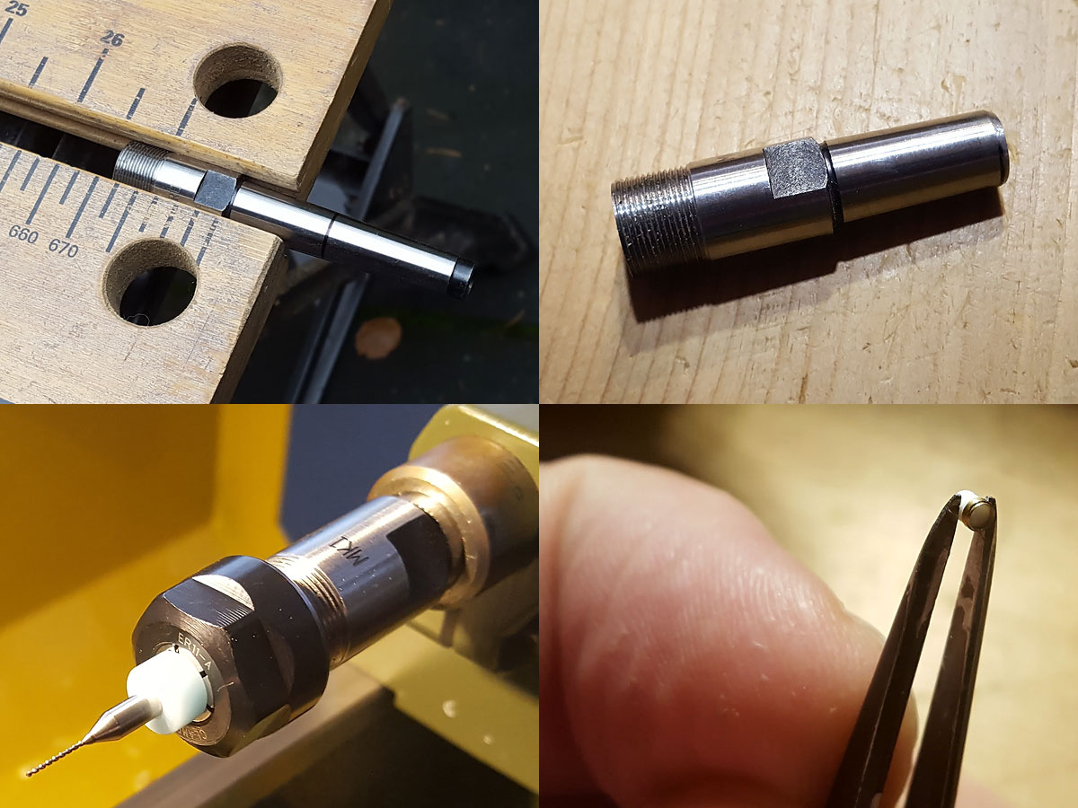
The collet chuck is comparatively pricey but I just had to take a bit off. Using drills with a 1/8″ shaft and ditto collet worked quite well. Nearly all my drills have a 2.2mm shaft and a 2.5 mm collet didn’t center them properly, so I ordered a new set of drills (only 30€ for 30 drills running from 0.1mm to 3.0mm in steps of 0.1mm) .
Postscript: I didn’t properly ‘snap’ the collet in the collet nut that may have been the reason the 2.2mm drills had an offset. In the nut there is an eccentricity on an internal flange that will cause the drill to be poorly centered if you just tighten the nut after placing the collet in the chuck. If the collet is first gently pushed past this internal flange (click!) and then placed in the chuck, not only is this problem solved (the problem being a poor user of fine tools), this eccentric flange will also pull the collect from the chuck when untightening the nut. Really clever engineering (post to be updated after checking the 2,5mm collet fit).
So it’s good news that the Proxxon tailstock that cannot be adjusted is well centered when it leaves the factory but a decent chuck apparently is not on the Proxxon menu. So, now the cost of a 20″ signalling projector is €60 each, but who’s counting…. At least on of the two major problems I have the with lathe is solved; the other one is that the top slide for tapering doesn’t have an accurate angle read-out.