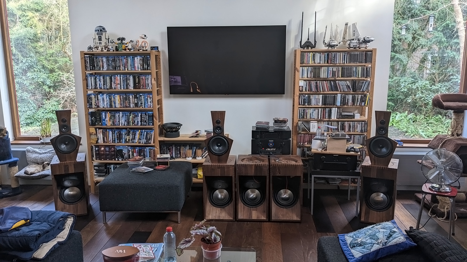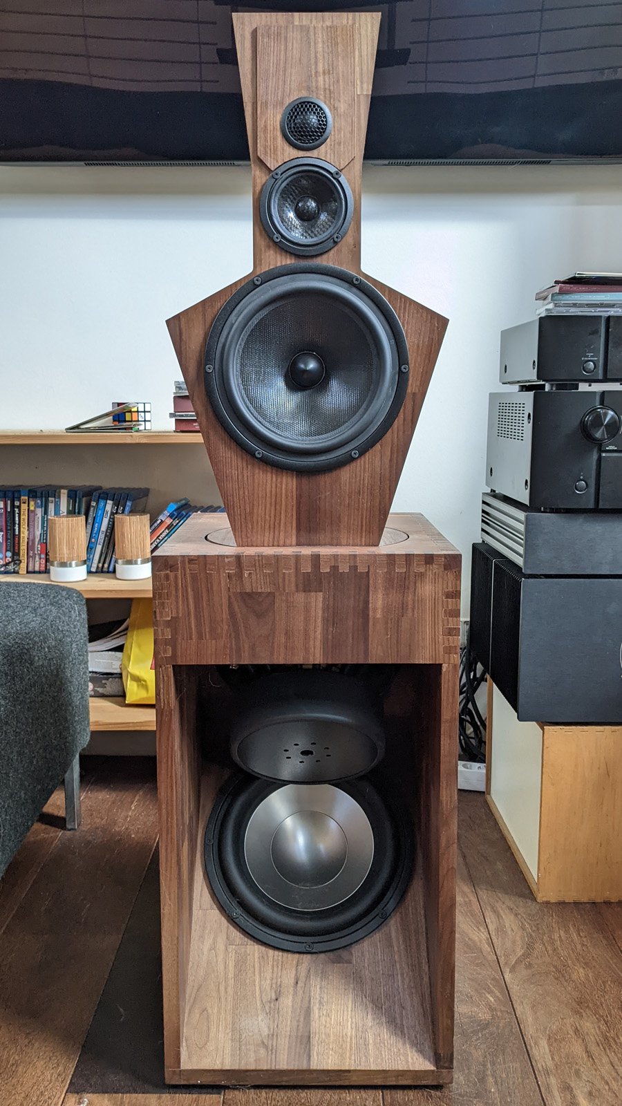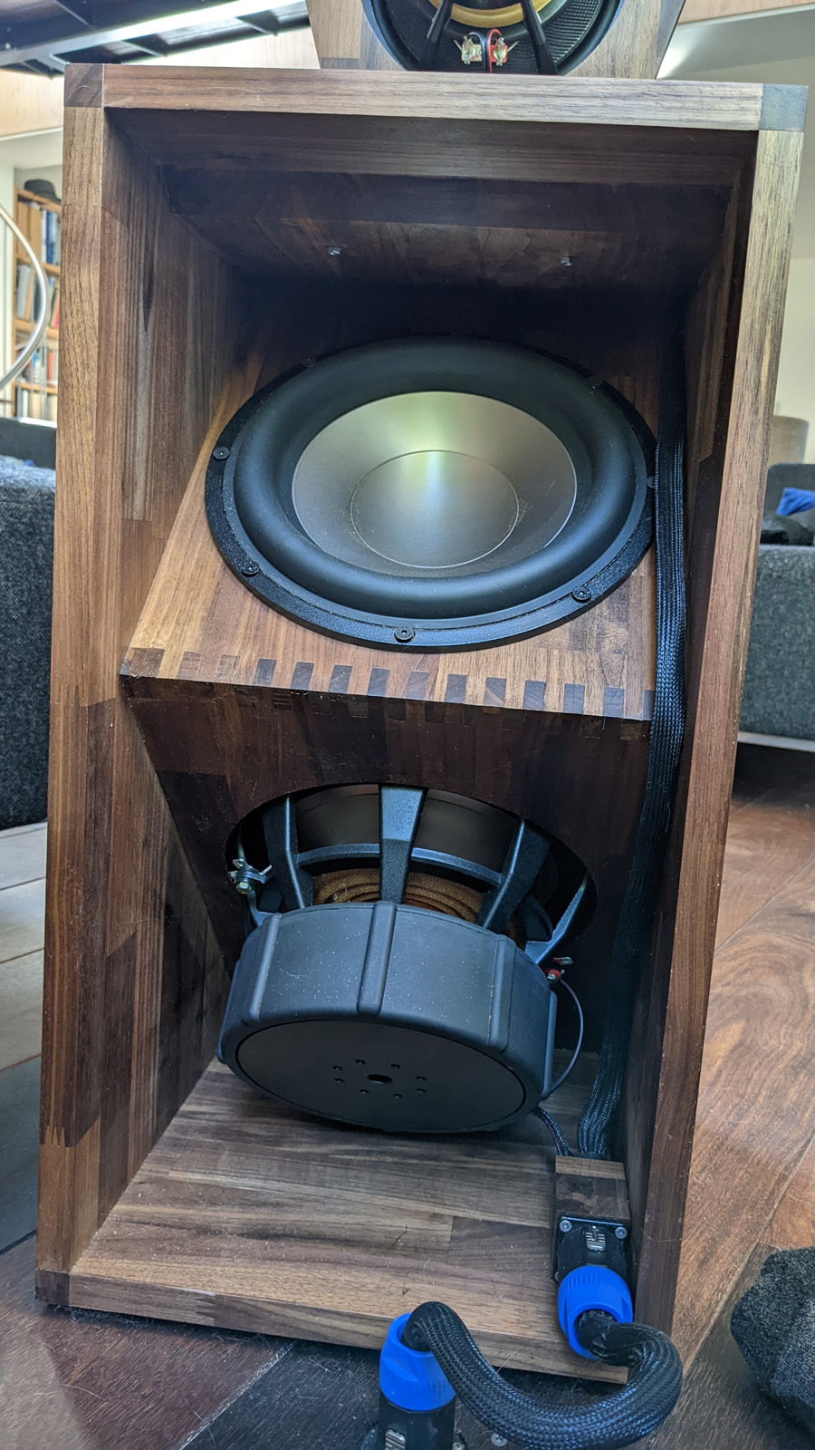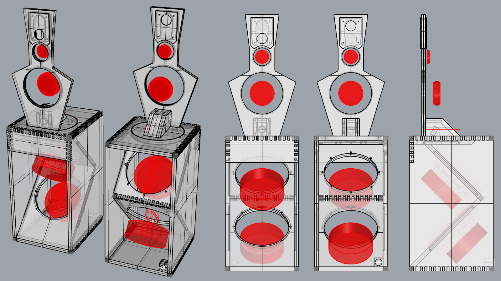
I wanted to make the LX521 in the same style as the Orions, that is, made from American Walnut panels with box joints. I made several small modifications to the original design, not really minding if this would affect the audio negatively. The original design uncouples the subwoofer cabinet and the top baffle by placing the latter on a bridge that rests on the floor. I removed that bridge from the design as a) it reduces the overall height of the speaker b) saves a significant amount of wood and c) I find the bridge visibly very unappealing. That latter statement may seem a bit odd as the LX521 isn’t really… easy on the eye. Now the top baffle is placed on four small motion dampers fixed to the top of the subwoofer cabinet to decoupling both components. I added an additional panel to the ceiling of the subwoofer cabinet, moved the subs around a bit, making sure that the top sub driver could still be placed and that the subs would not hit each other at maximum excursion.
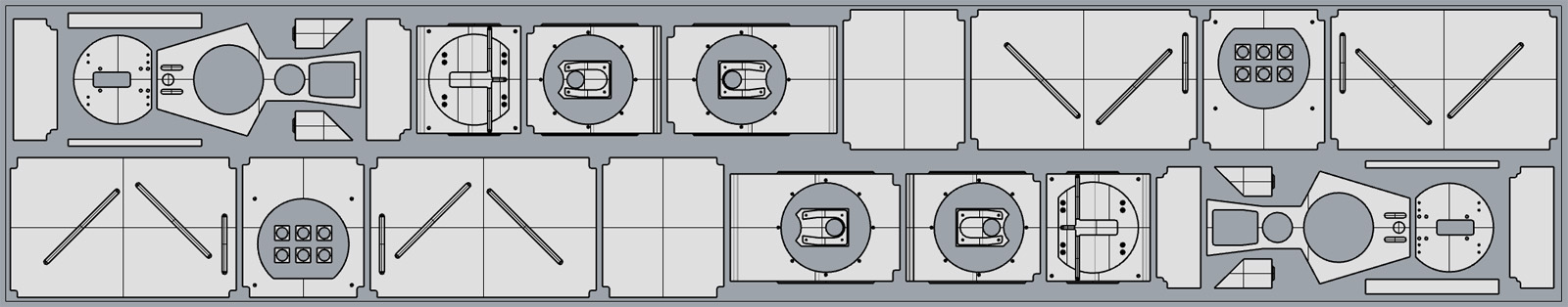
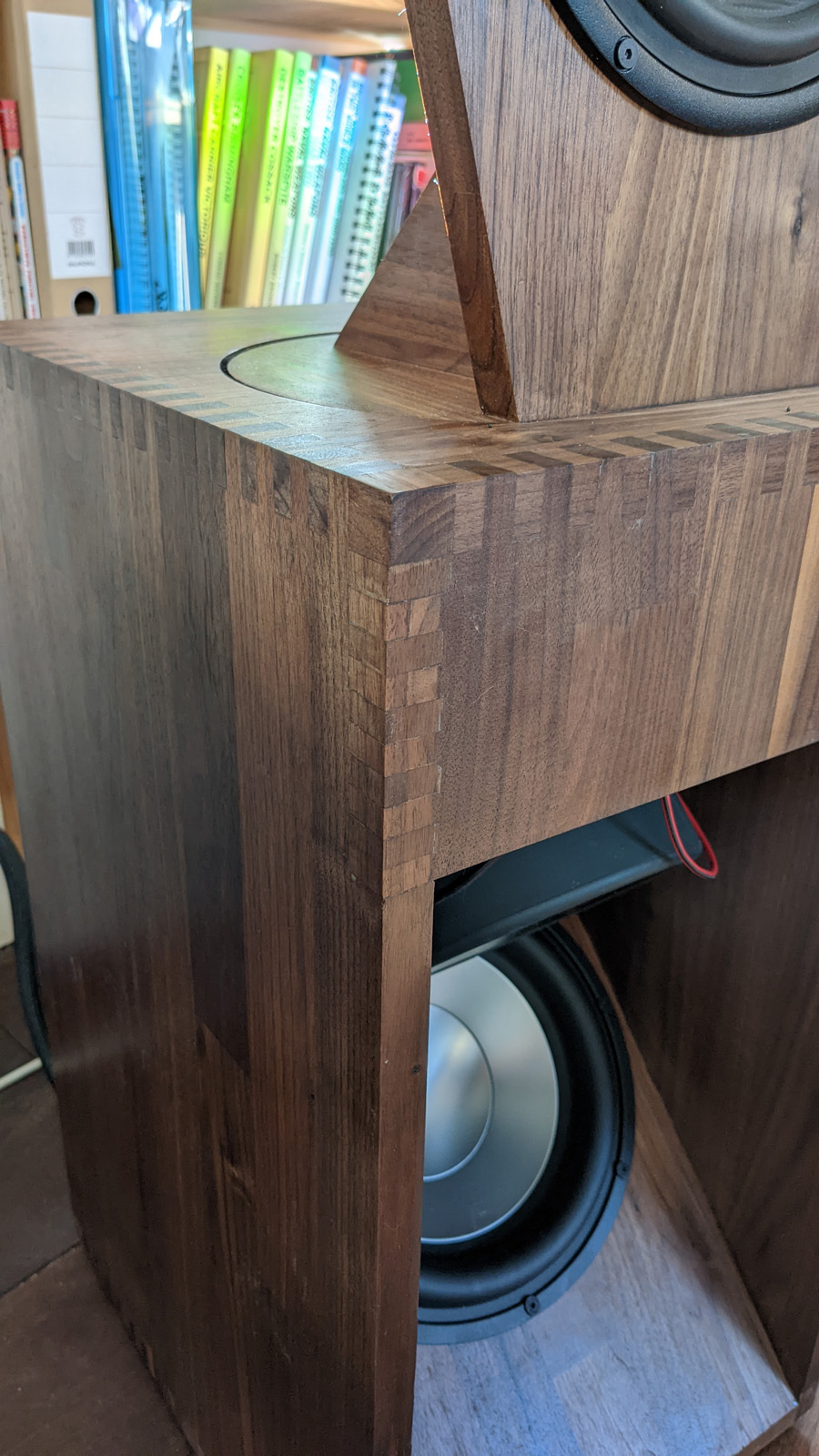
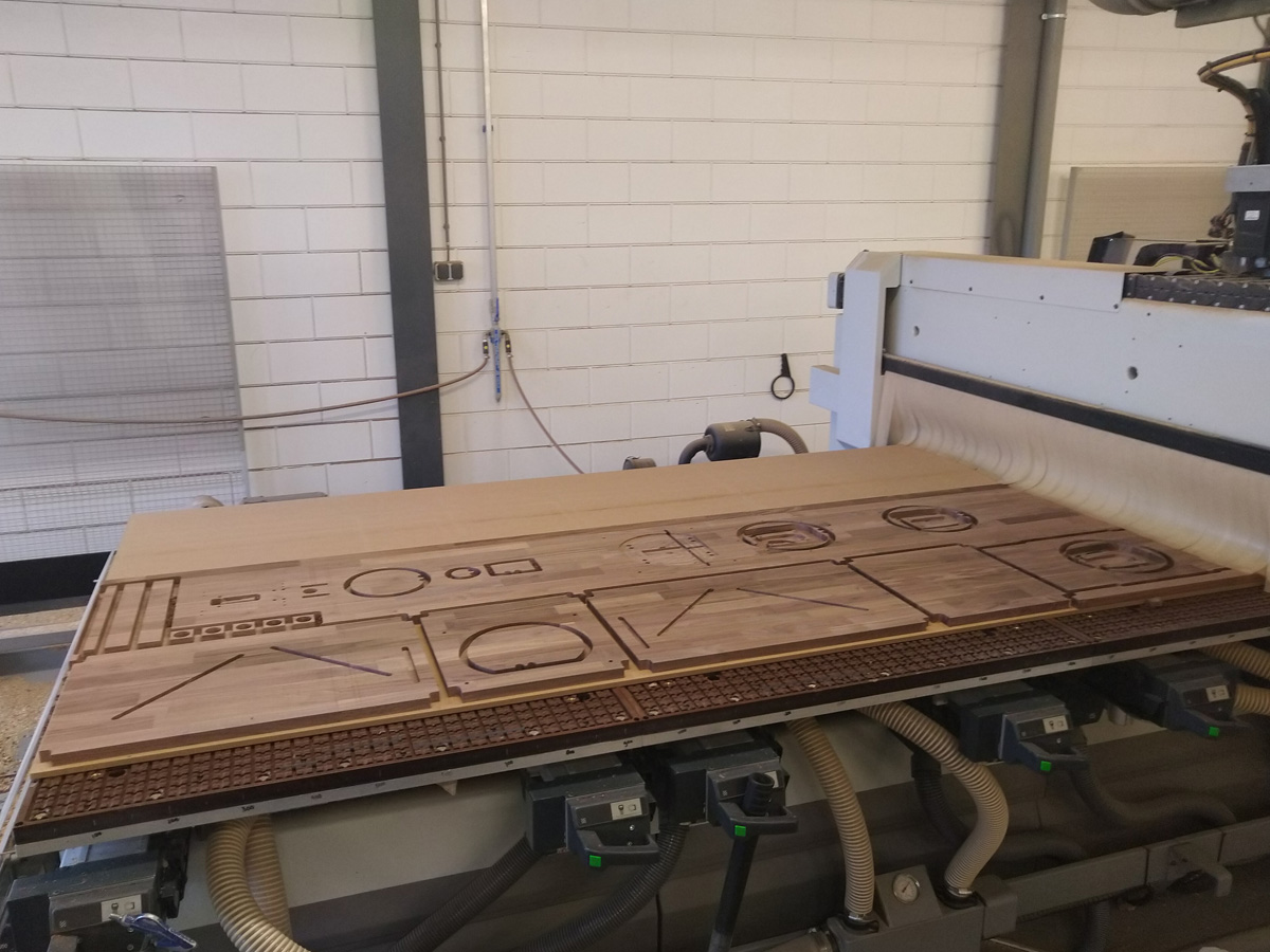
For the Orions I made my own panels from raw timber, but I decided to use premachined CNC panels from a larger Walnut panel. The cost of a panel was much larger than the cost of CNC-milling and would have saved me a lot of time in the work shop; for the Orions processing the timber to a panels took me about a week alone. One speaker would take exactly half a ready-to-use panel (4200 x 800 mm) leaving one set of spare parts when three panels were processed. I started with one panel, just in case there were major design errors. The panel was specified at being 19.0mm thick, as close as you’d get metrically to the 0.75 inch of the original design. The box joints have a thickness of 10mm, so to hide that difference in the corners small ‘cheater blocks’ are places on all corners of the subwoofer cabinet.
I had a small setback when the company that I selected to buy the panels and CNC work from moved between giving a quote and doing the design work; they forgot to take the milling machine with them. I called the importer of said panels that was right across the street of one of our facilities in Ede, Netherlands, and they recommended using AdZaagt.nl, who did a great job.
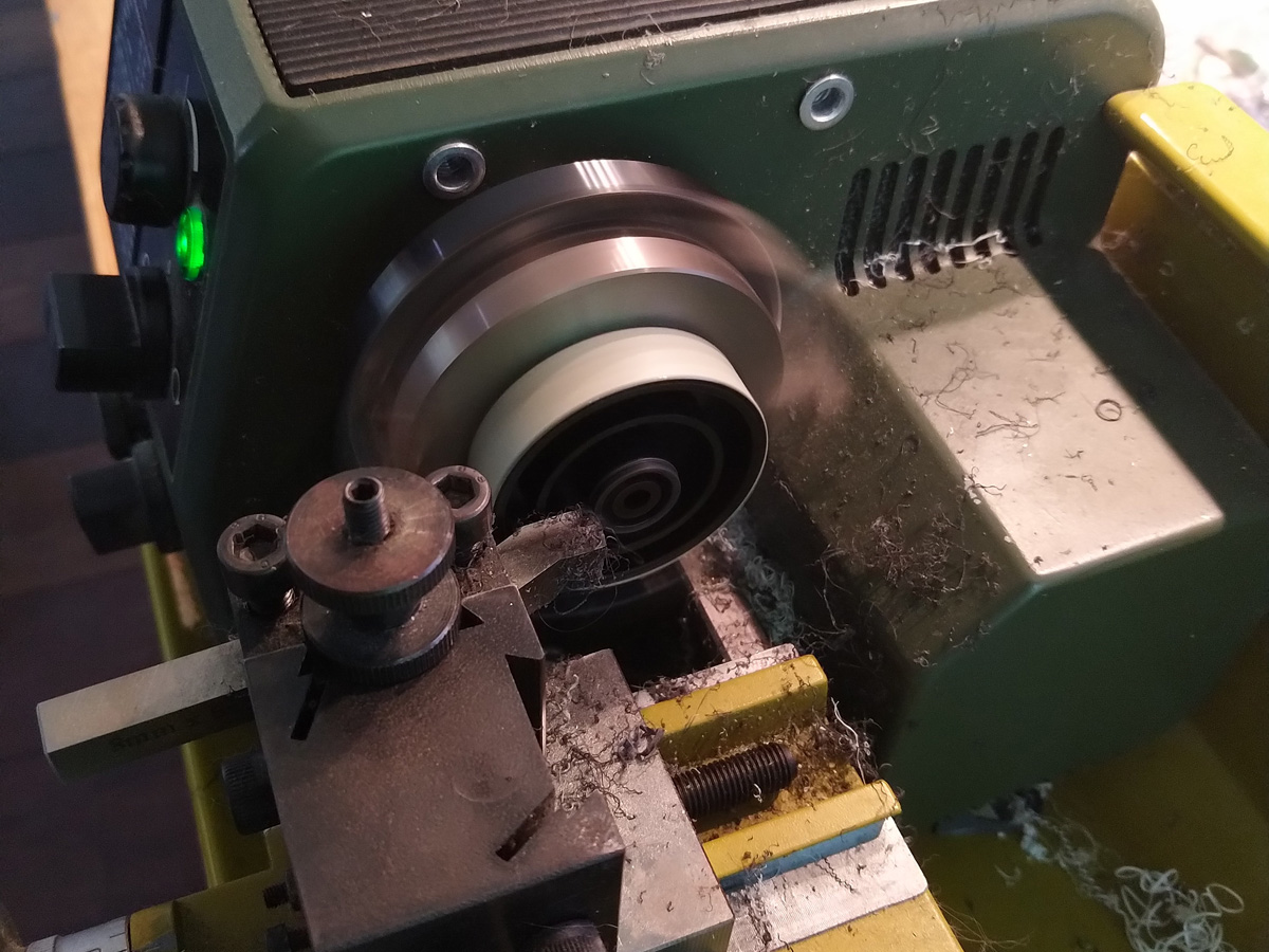
This is a picture I took during the milling process at their workshop (I took time off to watch…). There’s not a lot of artful woodwork with a CNC-machine involved, but your project appearing before your eyes was most inspiring. Fortunately there were no serious design errors.
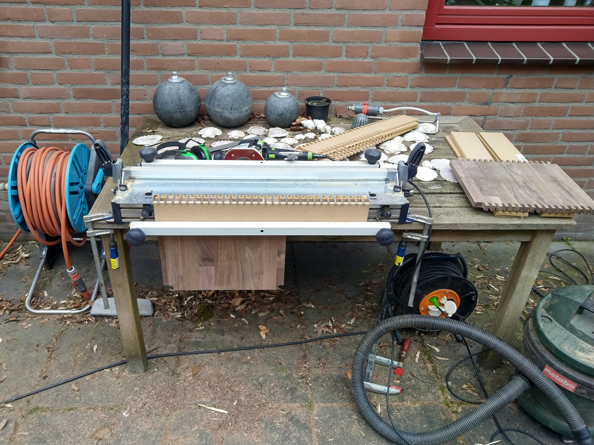
Box joints were added in the outdoor workshop using a Festool router and their VS600 joining template. This went quite well but I ran into a problem. The Walnut plate was not 19mm but closer to 20mm and some of the parts wouldn’t fit. I drove to a local tool shop, bought a new surface planer and spent several days planing and sanding the plates back to 19mm. This set me back a few days and several moods.
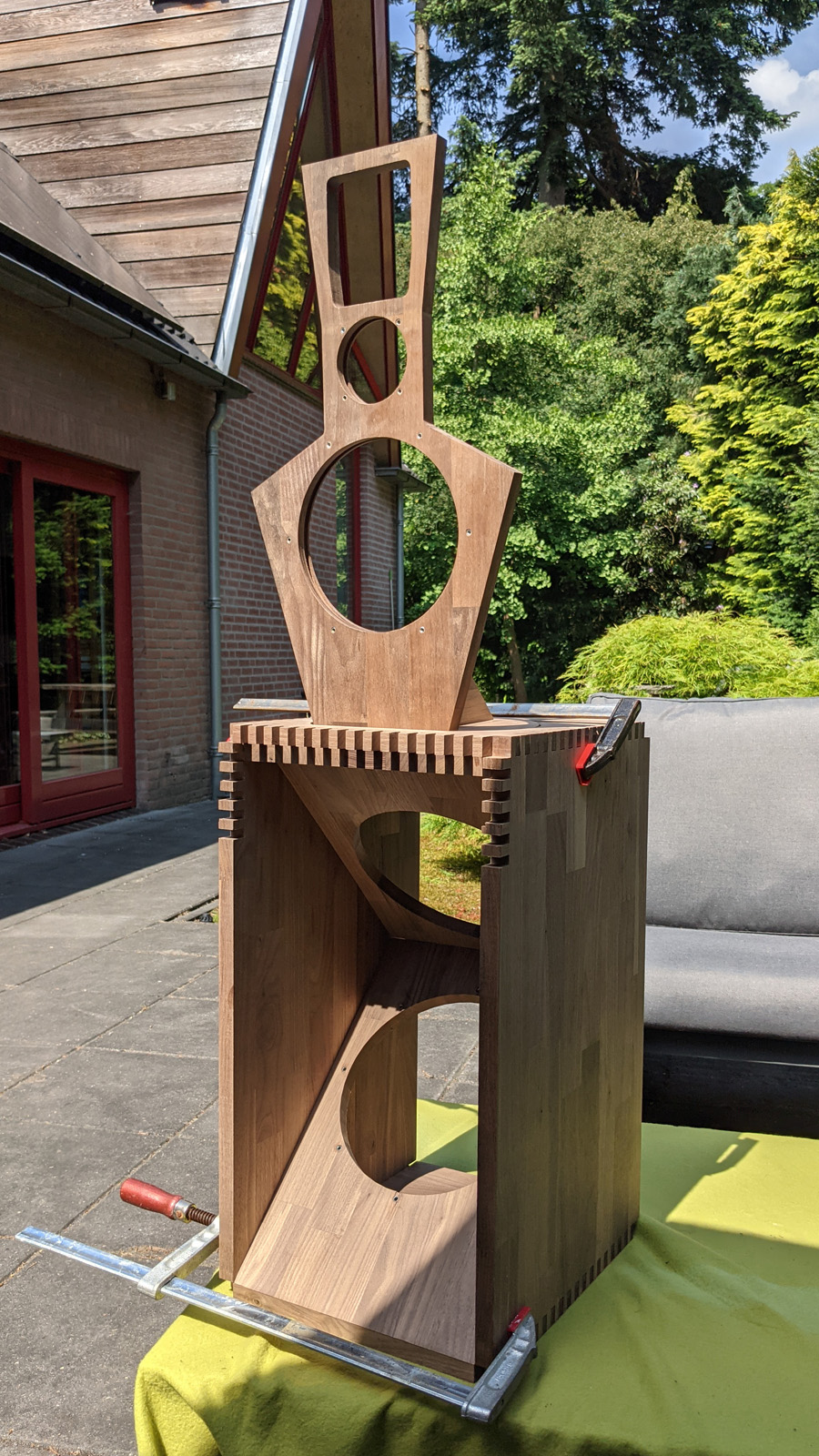
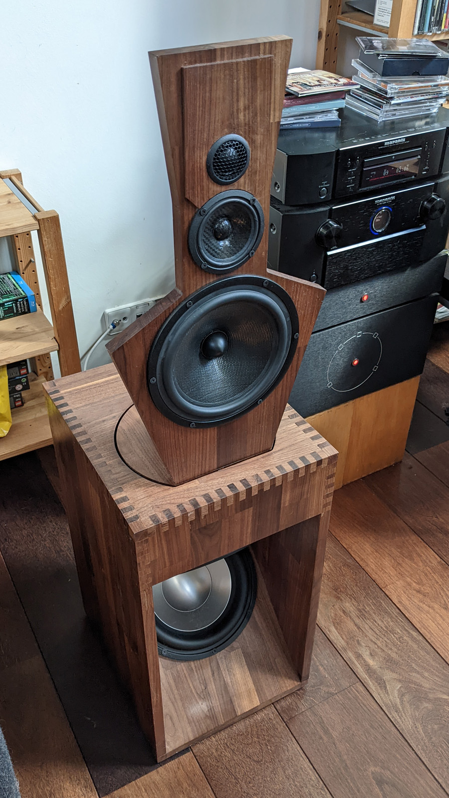
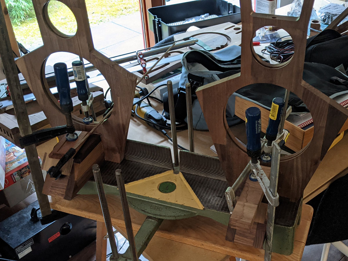
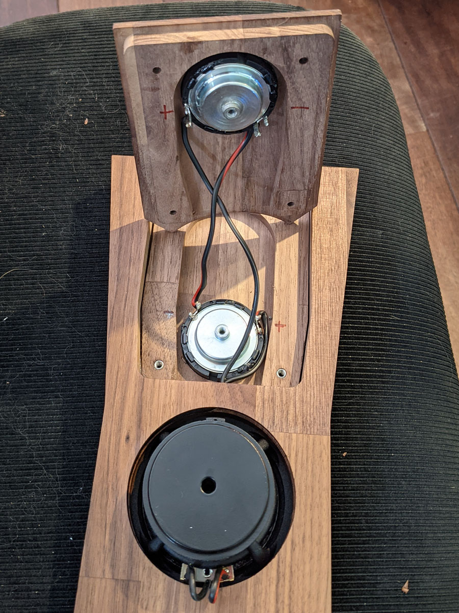
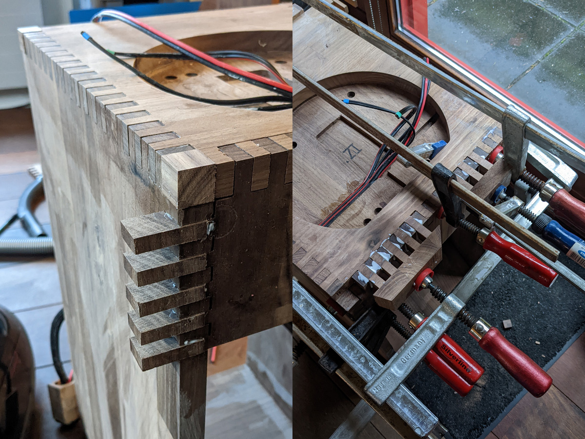
After some effort the first speaker passed its dry-fit test
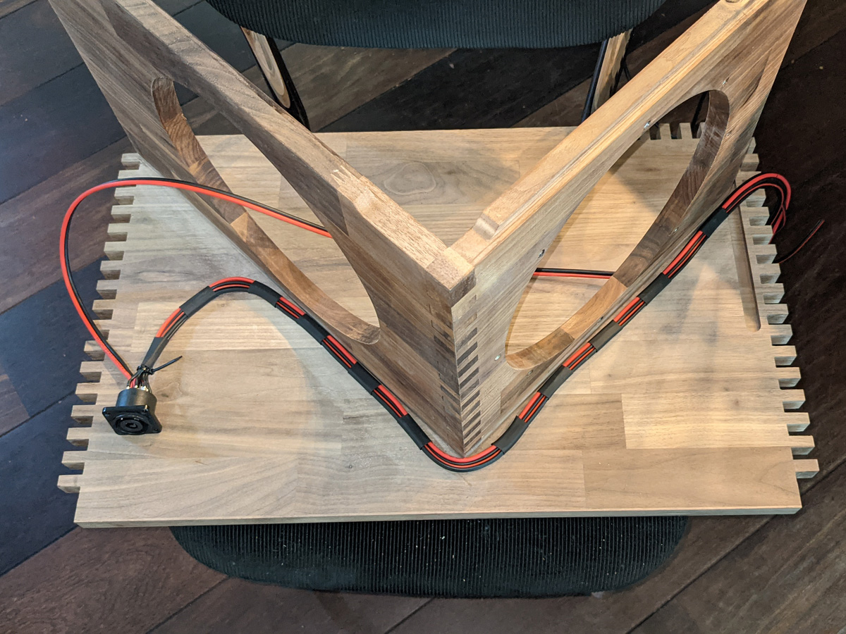
The cable towards the top baffle runs through the subwoofer cabinet.
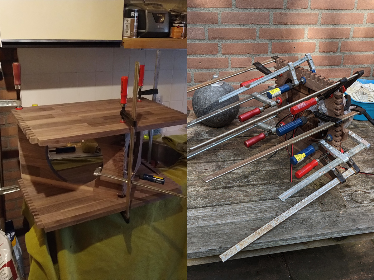
I do not think it is possible to own enough woodworking clamps; I always seem to be short!
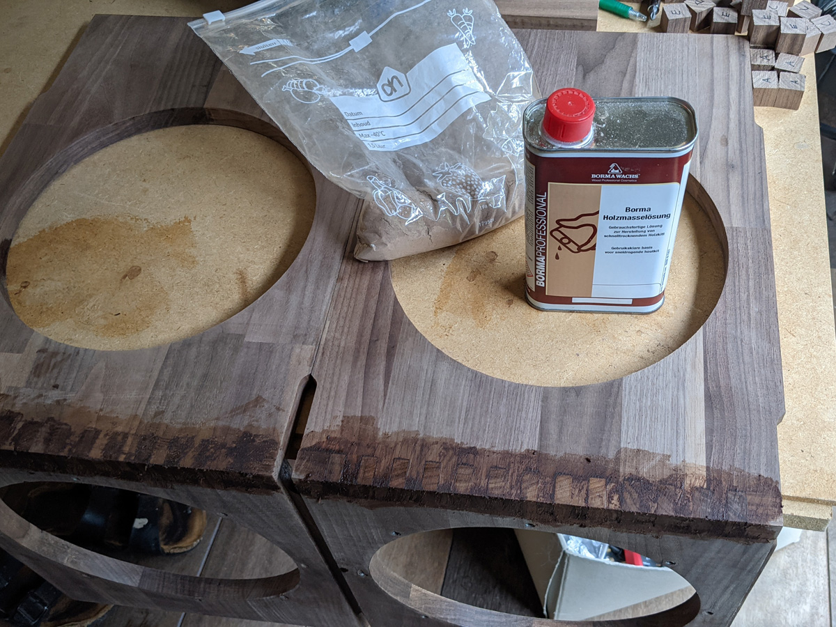
The joints were filled with this product, requiring a bit of sanding dust. The colour is never exactly the same and the filling shows, but it gives a smoother finish overall.
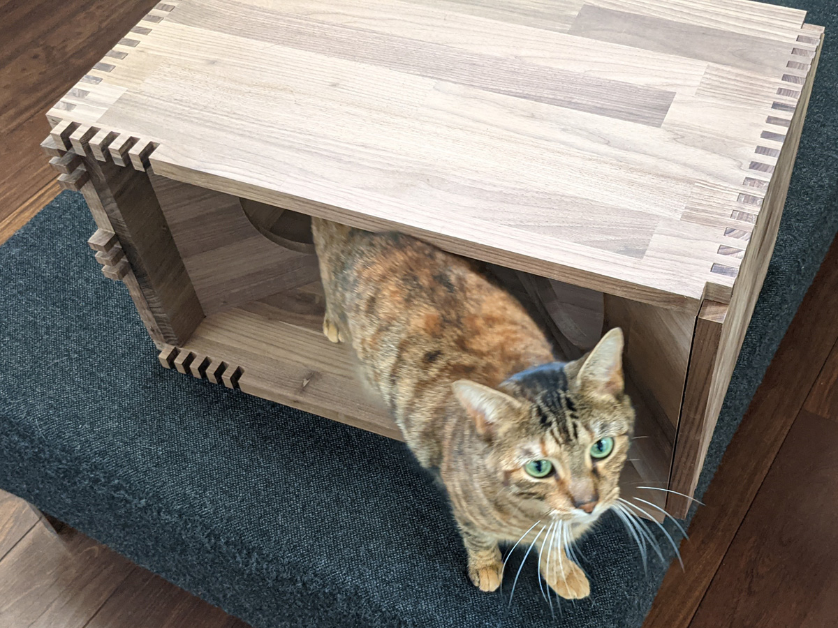
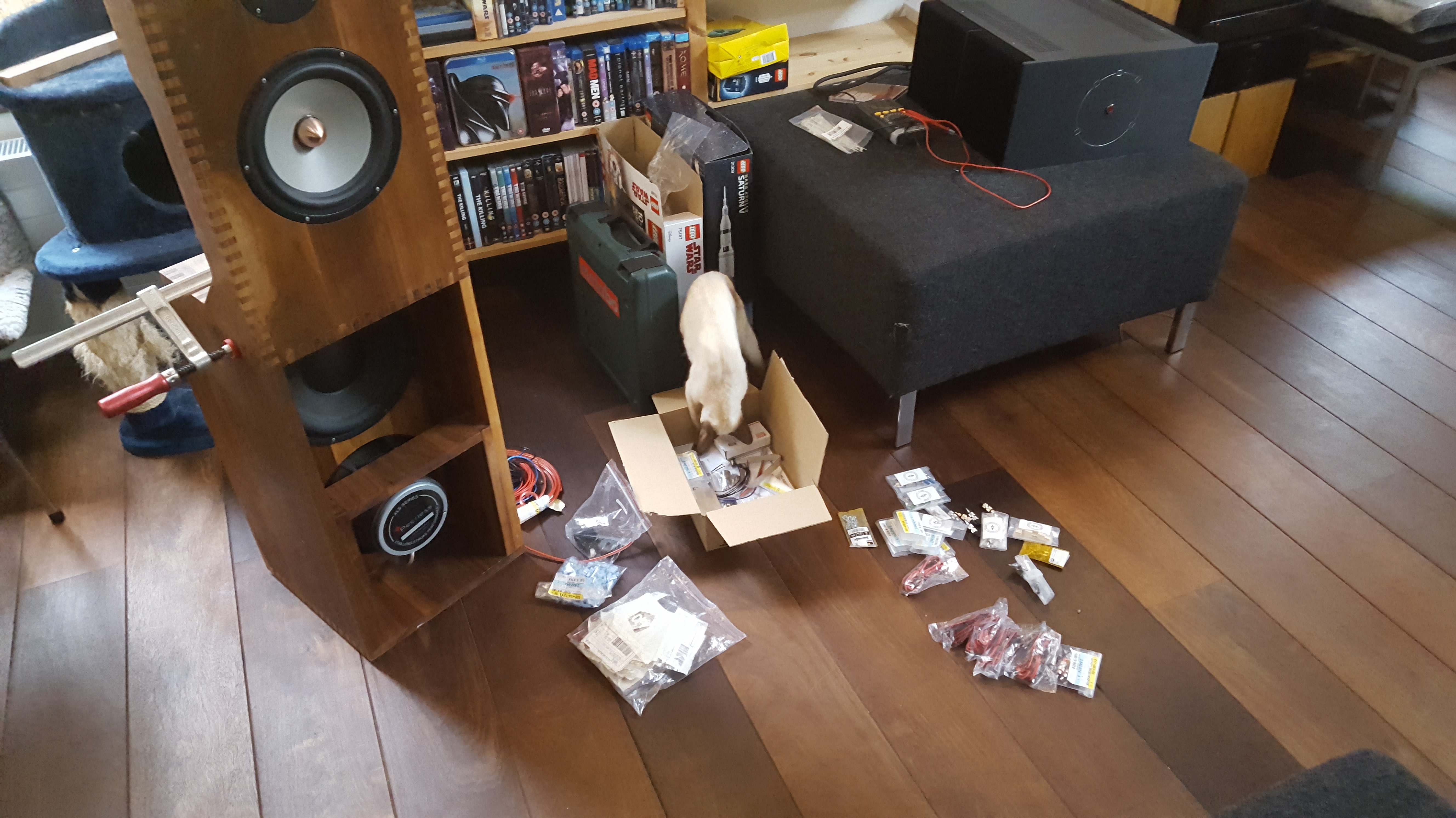
As the project moved into Winter some speakers had to be built inside with constant feline interference. The box joints appear flush, but I really should have added 1-2mm to the ends of the joints and sand afterwards.
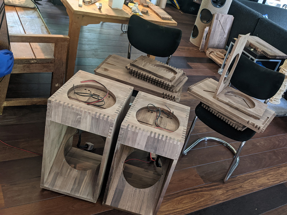
A proud progress shot. I took off three weeks during the summer to finish all speakers, but that was overly ambitious; the rest were built in weekends and during the Christmas vacation. I think I spent well over 240 hours finishing the cabinets.
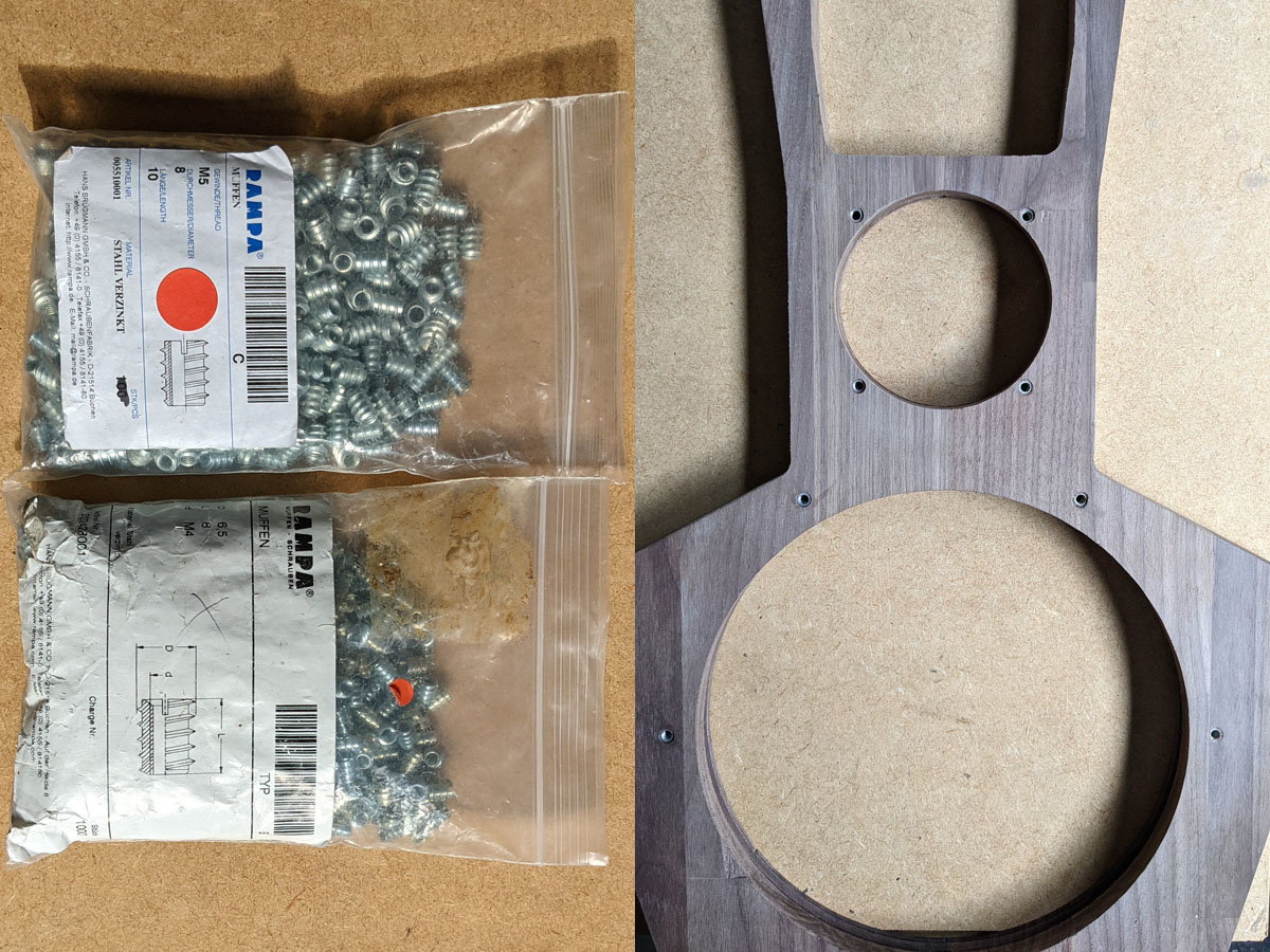
I used Rampa inserts so that all drivers could be mounted with M4 or M5 screws without running the risk of stripping the screw hole. I ordered a few but they shipped me a thousand each. These Rampa inserts are of type C that are narrowed for the same (internal) metric thread; even the upper midrange driver could be fixed using these Rampa inserts with the holes (5.5mm) so very close to the edge. For the baffle all inserts were M4s with M5s for the subwoofers; in hindsight that was a mistake, as you leave no room for misalignment; not all subwoofers could be fixed using all eight screw positions so this is definitely something to avoid for a next project. Hope that doesn’t result in problems with the wood reacting to humidity changes, but we’ll see. The Orions were built along the same principles with no problems over ten years.
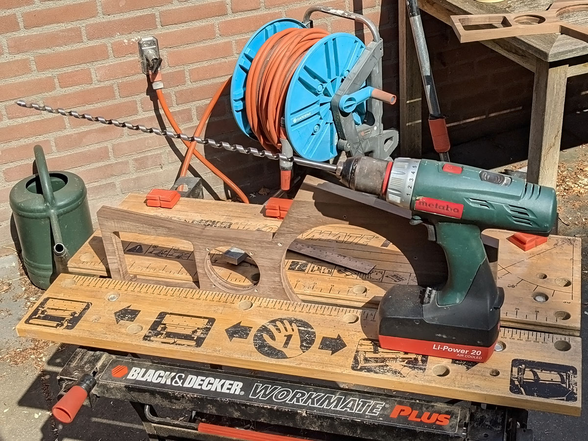
The speaker cabling does run internally for the top baffle, but there is a difference between adding a few holes in CAD and actually adding the holes in wood. I had to order a drill of half a meter for this one operation, eyeballing the alignment hoping not to ruin a precious panel.
A colleague borrowed me his Ulmia miter saw; this is not only an absolutely delight to work with but also doubles as a great clamping assist. The cable trenches were added using a small Proxxon router to the inside edges of the driver cut-outs. This brand-new tool burned out after 20 minutes; I didn’t notice it getting hot holding the tool at the router base and it did not have any thermal protection. At the shop this lousy “robust machine” suddenly changed into a “very sensitive tool you should not use for more than 10 minutes” but fortunately the damage fell under warranty.
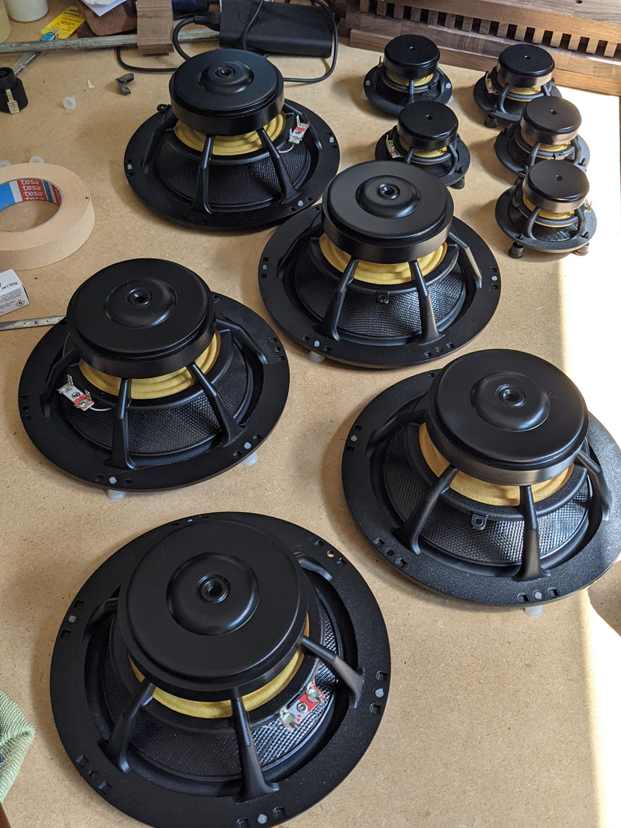
Meanwhile the driver magnets were all sprayed black.
The tweeters are slightly thicker than the top baffle and require a bit more room. The tweeters were simply glued into place and as I had the luxury of CNC machining I had two small inserts made to house them. Perhaps you can sand off the thread at the rear of the tweeter to reduce their overall height a bit?
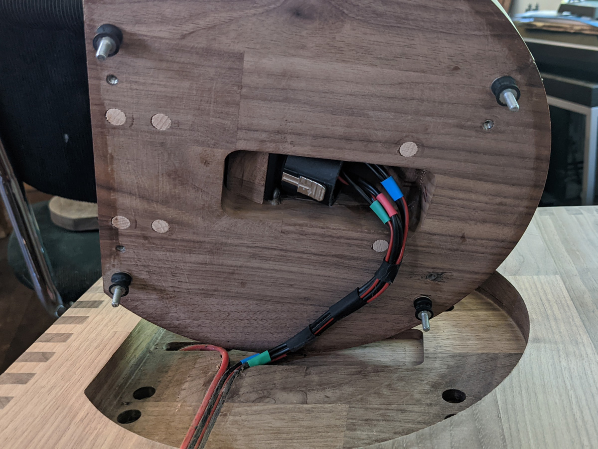
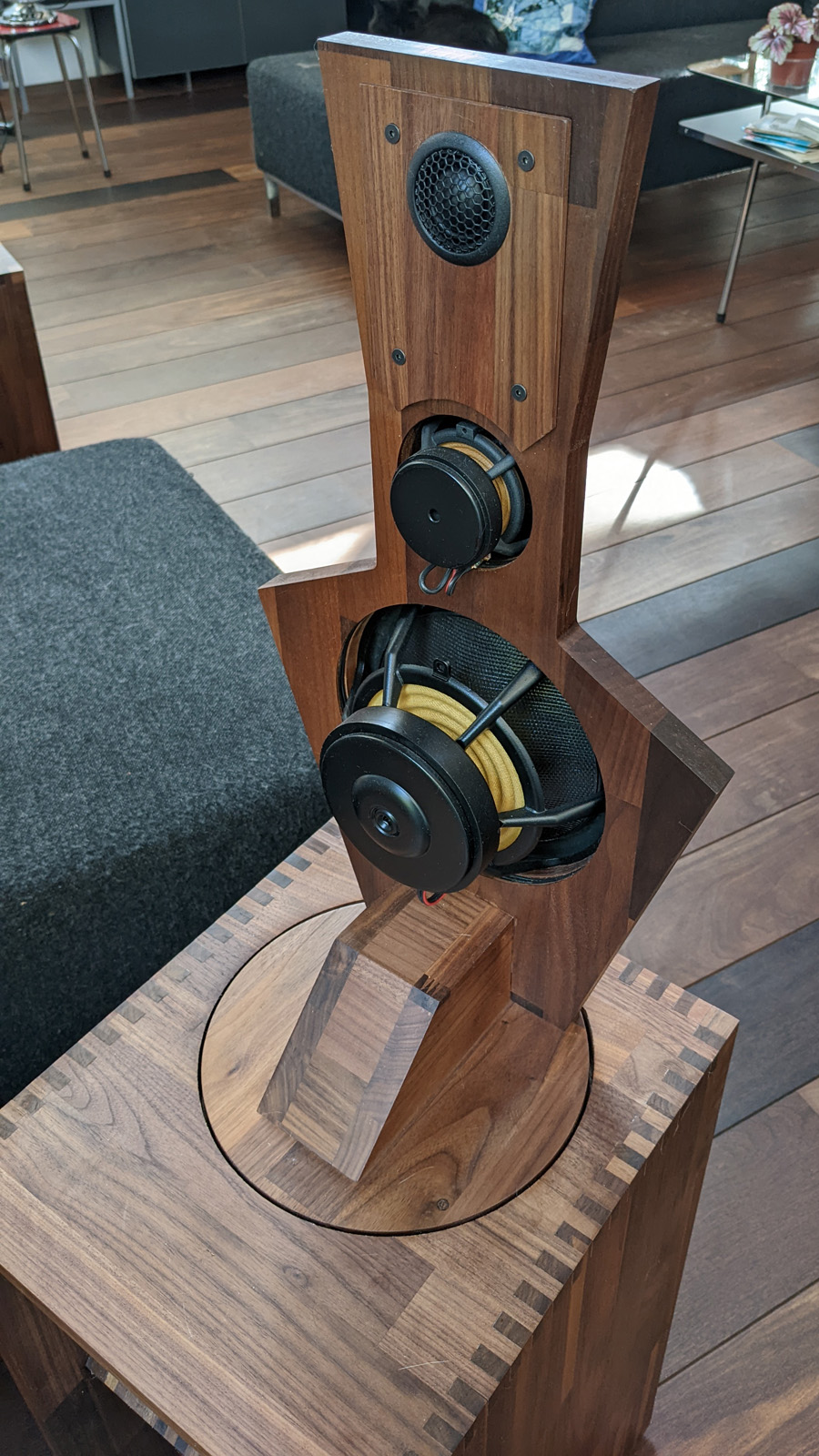
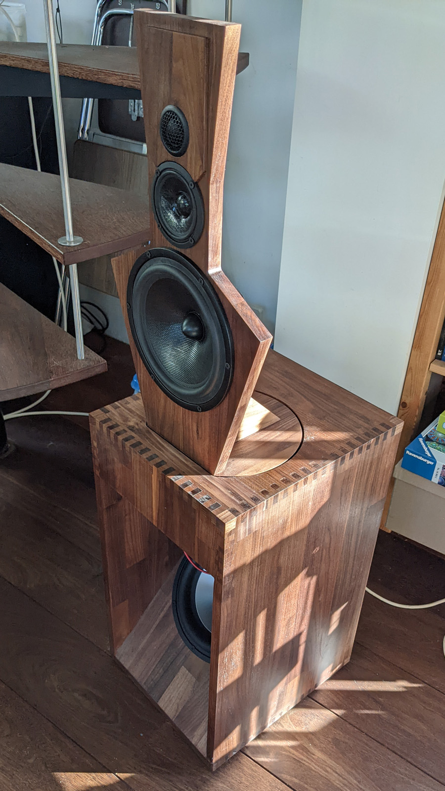
This shot shows how the cable from the subwoofer cabinet connects to the top baffle using another Neutrik connection. Most of that connector was sawed off to make everything fit. Four small motion dampers are positioned on each corner of the top baffle ground plate. These were the smallest I could find and I was worried the top baffle might move too much, so I added provisions for eight dampers. The movement of the top baffle proved to be negligible. I didn’t do any transfer function measurements or such and you can feel there’s a difference in motion between the cabinet and baffle when the speaker is playing.
There’s a small plastic spacer ring between the damper and the ground plate to align the top baffle; in the back there’s two 2.5mm spacers and in front two 3.0mm spacers. The thread of the top baffle runs through the top plate of the woofer cabinet and they can (just) be fastened by four small nuts (the entire top battle is very stable, but I wanted to reduce the risk of toppling the top baffle from the woofer cabinet). A torn damper can be easily replaced.
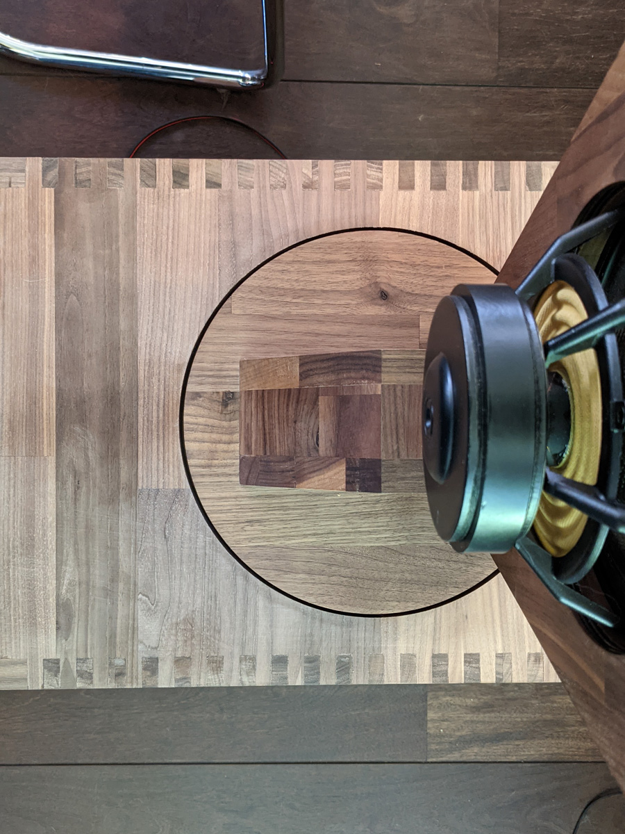
There’s a 3mm gap between the moving and stationary parts. After some (lateral) adjustments the top baffle fits just great!
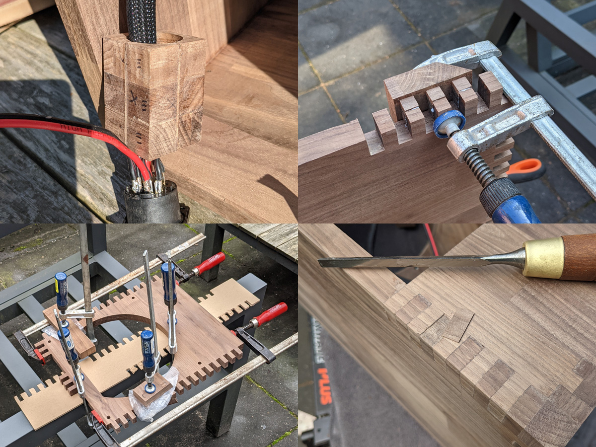
Of course there were many mistakes and CNC does not mean you do not have to spend any time make all parts fit.
- Top left shows the connector block that I forgot to add to the cable and had to be sawed open (I added two strips of wood to compensate for the loss)
- Top right shows box joint repair. Even with the panels clamped between MDF, the router would sometimes enthusiastically tear away large pieces of wood requiring dental work.
- And sometimes an entire panel just snaps in half. Note that this panel also lost most of its front teeth.
- The most-often used repair technique was the sliver transplant. Part of a tooth would be chiselled down and replaced by a slice of wood matching the pattern of the original panel.
After routing the box joint gaps, the panels would rarely fit immediately; there’s always some residual stress requiring a lot of correction work to make everything fit. But the front panel with the box joints applied along two grain directions was particularly troublesome and was worse during the winter construction. At left a major repair job is underway where all teeth were removed. The ‘cheater blocks’ are well visible on the corners, prior to sawing and sanding all parts to size. And at right a well-controlled nervous breakdown is observed where basically the entire upper jaw was replaced.
LX521: introduction
LX521: deriving the digital filter
LX521: building the analog filter
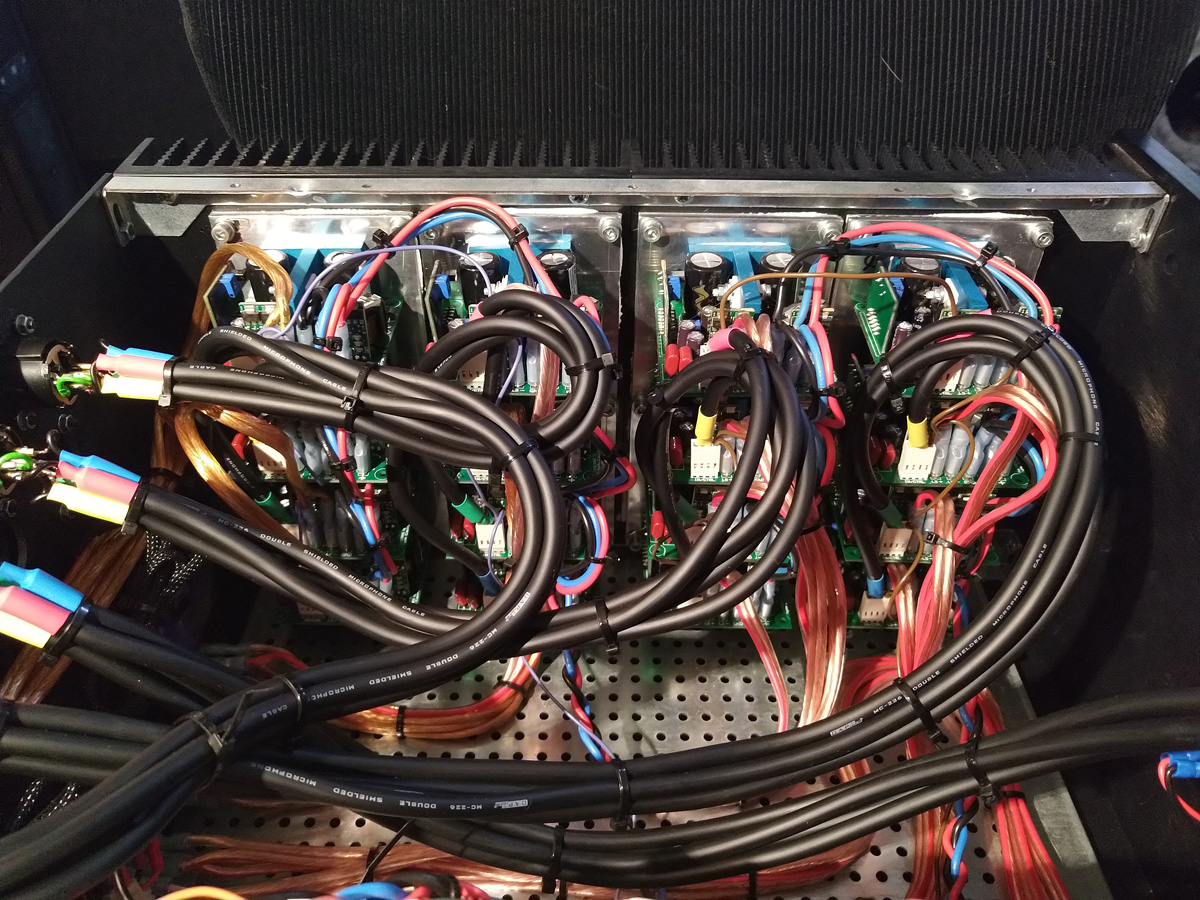
LX521: building the power amp
LX521: building the speaker
LX521: results