
The various components were not built in a linear fashion and the amp with two channels was completed before I started the Analog Signal Processing unit. About two years passed between the original amp with two channels plus the miniDSP2x4s for the Orions and the final version for the LX521. My previous version of my DIY Orion PCBs (ASP board) worked really well, but the LX521 user group produced a PCB, a shopping list, a manual, and troubleshooting guide. I was apprehensive about the DIY route versus a ready-to-use design that had been rigorously tested and choose the latter; this is a decision I came to appreciate later when trouble shooting.
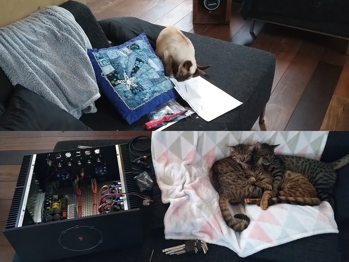
These ASPSs certainly do not fit in the amp enclosure where there is a noise risk, so I bought a small, separate enclosure. While my Siamese Catherine ate the manual of the new enclosure my new cats were given amplifier therapy, teaching them that amplifiers are friends and part of their natural environment. Meanwhile I suffered more self-induced problems by straying slightly from the path by wanting to have five channels.
So, the preamp can be either balanced or unbalanced and the ASP can take either signal. However, its output is an unbalanced connection. This is a small drawing of the ASP and the connections to the power amps following Hypex’ recommendations for an unbalanced output: a balanced cable has both its pin 1 and pin 3 to the signal ground and than happily continues as a balanced cable inside the amp enclosure. Internal and external shields go to the chassis grounds but at separate locations.
Now, I added five ASPs in a semi-spacious enclosure with additional internal cabling. The amp itself was already built and had five connectors for the pre-amp signal to run to the DSPs I wanted to have in the amp enclosure (the balanced miniDSP was shielded, so why not?). With the ASP I had only one connector so I used one XLR-6 connector per speaker and a five-core shielded cable. For some reason I started with an unbalanced cable to the XLR-6 OUT connector and ALSO tied pin 1 and pin 3 on the inside of the amp AND connected internal and external shields to each other at all locations where I could. I cannot really recall exactly why I thought it was a good idea and in hindsight this was also really unwise; I made an all-noise surround system and had to re-cable everything.
So the internal cables were replaced and I also made sure that the shield of an external cable was not directly connected to the shield of an internal cable. All four channels do share the same signal ground in the interlink, but soit, they do so on the ASP-side as well.
I later considered using a network cable; these have four individually shielded twisted pairs and form a much neater and smaller connection (despite the graphs showing “more cable”). I was worried about connecting the flimsy shield on a network cable to the connectors on the Hypex side and already built the XLR-6 cables. Cabling and connectors are a significant money sink that added many hundreds of Euro’s to the entire system already, so didn’t pursue this option.

So one signal cable/channel is a bit of a monstrosity with four signals, four signal grounds twisted into a single point, and the shields (pin 1) connected to lugs. The individual cables have lavish colour coding per channel and per speaker. This saved me on more than one occasion and heat-shrink tubing is cheap. I removed a bit of the anodized layer where connecting the shields to chassis.
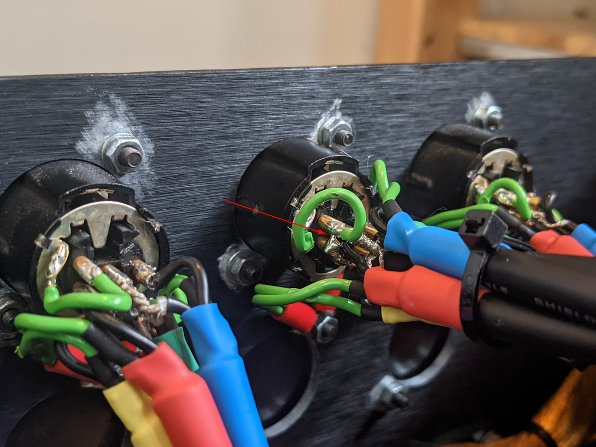
A close-up of the cable (actually, this is in the amp, not the ASP) shows the universe has a sense of humour and tried connecting the sub signal to ground; this happened at the same moment when one signal connector got loose at an amp module for the other speaker, resulting in no sound in both forward speakers at the same time for the subs only resulting in a minor panic attack.
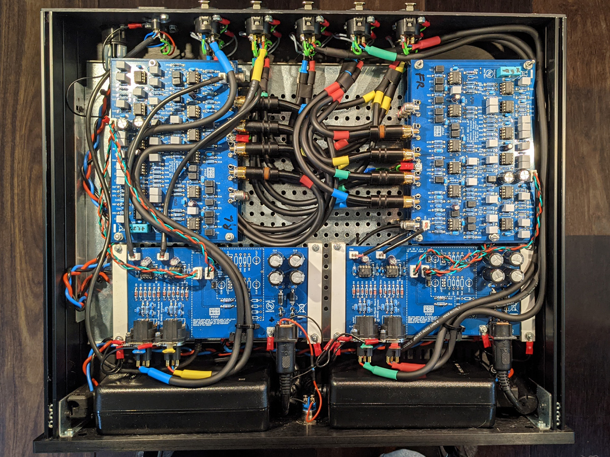
Top view of the final setup. The power connecting enters the chassis top left and runs to a Audiophonics mains trigger below the bottom-left power board; two power boards are stacked bottom-right, with the top board feeding the lower board. At the bottom two Meanwell power-supply units are wedged in. The ASPs have their chassis grounds connected to the bottom plate (connected to safety earth at the mains in).
I was worried about running 230V and PSUs in the ASP enclosure but I could not find any audible effect of running the mains near the ASPs. Admittedly, there is a minute bit of hum coming from the speakers if you are very close to the mid drivers, but that is acceptable to me. The stacking system was made from polystyrene sheet and tubes from my modelling supply with the boards connecting to the chassis ground via some mounting pins (M3 thread).
LX521: introduction
LX521: deriving the digital filter
LX521: building the analog filter
LX521: building the power amp
LX521: building the speaker
LX521: results