
The Analogue Signal Processing filter (ASP) of the Orions is a separate Printed Circuit Board (PCB). As the signal is not yet amplified and doesn’t at all depend on the amplifier/filter/driver/speaker interaction, you can build and test the filter separately. A PCB can be ordered directly from Linkwitz, but I thought it would be nice to make it myself so that I could fit all five in one casing. I hadn’t designed a PCB before but with the help from our electrical engineer at work I managed. I used the PCB design program Eagle to first draw the circuit and then place the parts on the circuit board. Eagle can add the routes between parts automatically, but I wanted to do that myself as well. As an extra cumbersome challenge, I wanted to have all routes on one side only. I suppose this added to the general idea of solving an intriguing puzzle. With the electric scheme that came with the plan set it was little more than connect the dots and paint by numbers to make the PCB work.
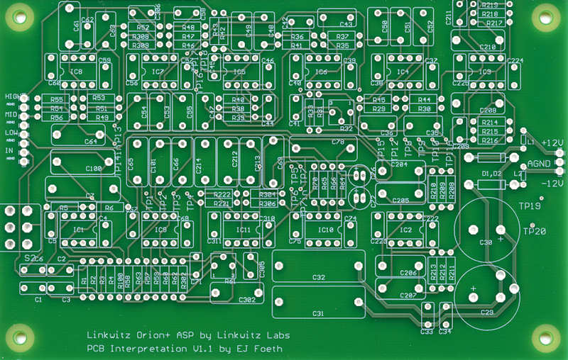
This is the signal route side with the locations of all the parts. This is really a complicated design especially compared to my old speakers that have only two filter components total (the midrange driver isn’t even filtered). The theory behind the filtering is all explained in wonderful detail on the Orion Website with a nice decomposition of all the ingredients and their complex (i.e., not real) gain and phase transfer functions. I designed this PCB with all parts fairly close together. I started by ordering a single test board that was error-free and sent my order for 5 revised boards priced to Eurocircuits; they sent me six.

Here are the boards fully loaded. As I ordered enough parts for the 6 boards and one test board, I decided to load them all should one fail completely. I found soldering all the parts in place quite calming.
I tested all the boards and they all worked fine; I had a bit of stray solder short-circuiting one board (nasty burn) but that was quickly solved. These are measurements of all boards showing the transfer functions of the gain for the three frequency ranges and this is what they are supposed to look like. They are nearly the same, quite surprising given the few percent of uncertainty in the value of capacitance and resistance of all components. The current boards are Orion version 3.2; the Orion and its ASP received a few updates over the years that are not yet implemented.
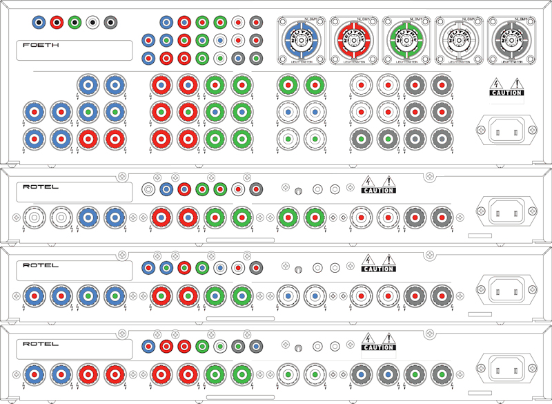
The boards were placed in the casing of an old Rotel amplifier; the height of the amplifier actually determined the maximum width of the PCBs and precluded the use of the standard PCB (the reason I made my own PCBs). I first asked the Rotel importer if I could have a Rotel casing, but they scorned at this indecent proposal. So I watched the second-hand market until I found a defective amp that was disembowelled. The rear panel of the amp was replaced by a sheet of brass hammered into shape and supplied with a very large collection of holes, plugs, sockets and connectors. The colors indicate the channel (ring) and the driver (red/blue/green for bass/midrange/tweeter).
Note that there are five large connects top-right by Speakon; these can be fitted to a speaker cable with 8 cores. I choose to have the pre-amplified signals run to all amplifiers, collect all the amplified signals back to the filter cabinet and move them internally to the Speakon connectors for an easy connection. This way the ASP cabinet and three amplifiers form one block with only five preamp signals and five Speakon connectors to disconnect when moving the gear. The complicated business of sorting out how to hook up the speakers is now simplified making the filter casing a ‘black box’.
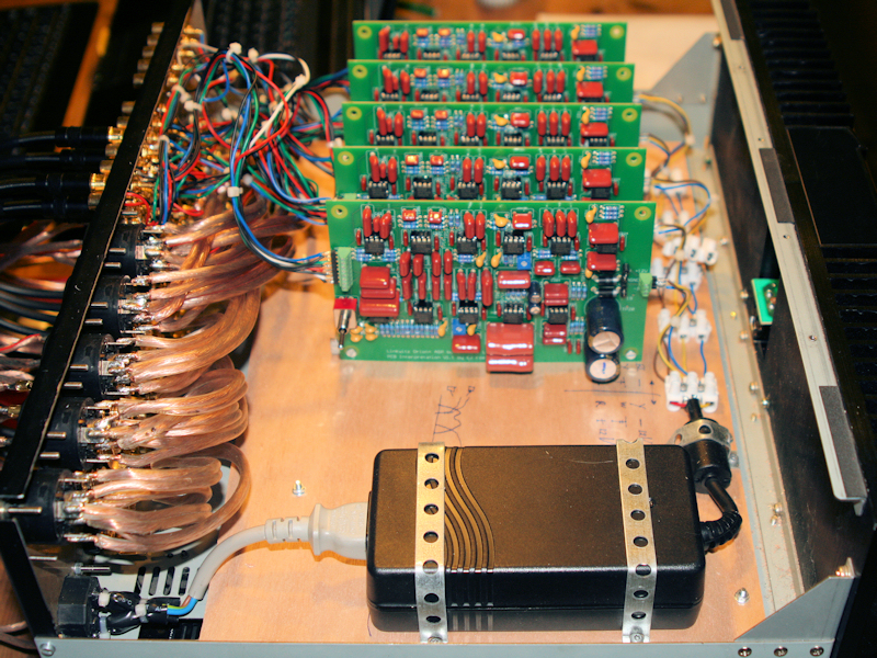
A view of the inside of the filter with the power supply bottom right, the signal cables to and fro the filters top left and the amplifier cabling bottom left. After all the connectors and plugs and sockets were placed, the rear panel sprayed black, and the soldering completed—taking well over two days—I ran another test of the signal boards. It took some time to work out how to measure the ASP performance with a program called ARTA (meanwhile this is a few years later after finishing the filters) but after the right settings in Windows were found all the characteristics returned nicely. More than fifty cables running on the outside of the filter were made.
Sub project complete!
Introduction
The plan
Design changes
Signal processing
The listening room
Production
Listening