One additional challenge is the filtering for these speakers; these are active speakers with an elaborate filter; for the LX521 I certainly could not use the Orion filters. Adding a programmable Digital Signal Processing (DSP) unit would make sense.
I bought a small miniDSP 2×4 kit to experiment with, a a budget card with analog inputs and outputs. Digital filtering for audio is something I also know nothing about, but I do have some experience with signal processing of underwater radiated noise. This project came in handy for gaining some experience with acoustics and solving the speaker filtering, as from a mathematical point of view solving loudspeaker filtering is quite straightforward compared to sonar array processing. How to design a loudspeaker filter to produce the sound you want is something entirely different and a critical component of loudspeaker design, but these are supplied with the building plans so I only had to simulate the filter with freely available tools.
So, some technicalities. The analog filter is a combination of default ingredients and for the digital filter you have an equivalent; these filters are expressed in biquads, a simple parabolic expression. A filter transfer  is defined in biquad terms as

with  the complex transfer defined as

For the miniDSP implementation you divide all terms in by  and
and  are
are  negative, and you get

MiniDSP offers a great spreadsheet for all types of filter that could be easily moved into Matlab. For instance, for a second-order high-pass filter you have the following definition


with

so that depends only on the parameters  ,
,  and sampling frequency
  . Some filters need more or different inputs so in the end you are only left with at most four inputs , ,
  ,
,  , and the filter recipe. I added one additional term to shift the entire transfer by a gain
  dB by multiplying all coefficients by a gain
  , and, a full phase inversion, (flipping the sign of
  ). Higher-order filters are simply the product of two lower-order filters. For instance, the 4th-order Linkwitz-Riley so predominantly present in the Orion and LX521 crossover is simply the product of two second-order filters. You can write the entire transfer more generally as

for all of the  components. Expressed in dB the total transfer is
  . But there is a catch.
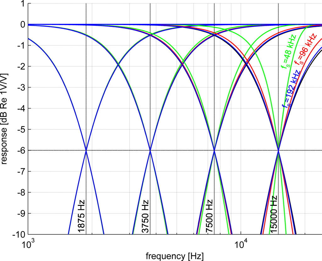
This chart shows a collection of transfer functions of these Linkwitz-Riley filters (LR) for four different cross-over frequencies (i.e., different values for and IIRC  ). We have a several colors that represent the transfer for different sampling frequencies: black (
 ), blue (=192 kHz), red (=96 kHz), green(=48 kHz). It is fairly obvious that the resulting transfer depends heavily on the sampling frequency the closer you get to high-frequency range.
One wonderful property of the LR4 filter is that the (complex) sum of the low pass and high pass components is constant and this property is retained in this DSP implementation. But the DSP I bought (the 2×4) has a sampling frequency of only 48 kHz. Translating an analog component by simply plugging in the design settings will not give you the correct transfer function. So I could be in trouble… I measured the 2×4 miniDSP response and it matches the theoretical transfer perfectly; it’s a property of the biquads and not the miniDSP.
Following some leads of other people on the OPLUG forum for an older Orion DSP implementation I added an equalization filter and managed to get the required transfer.
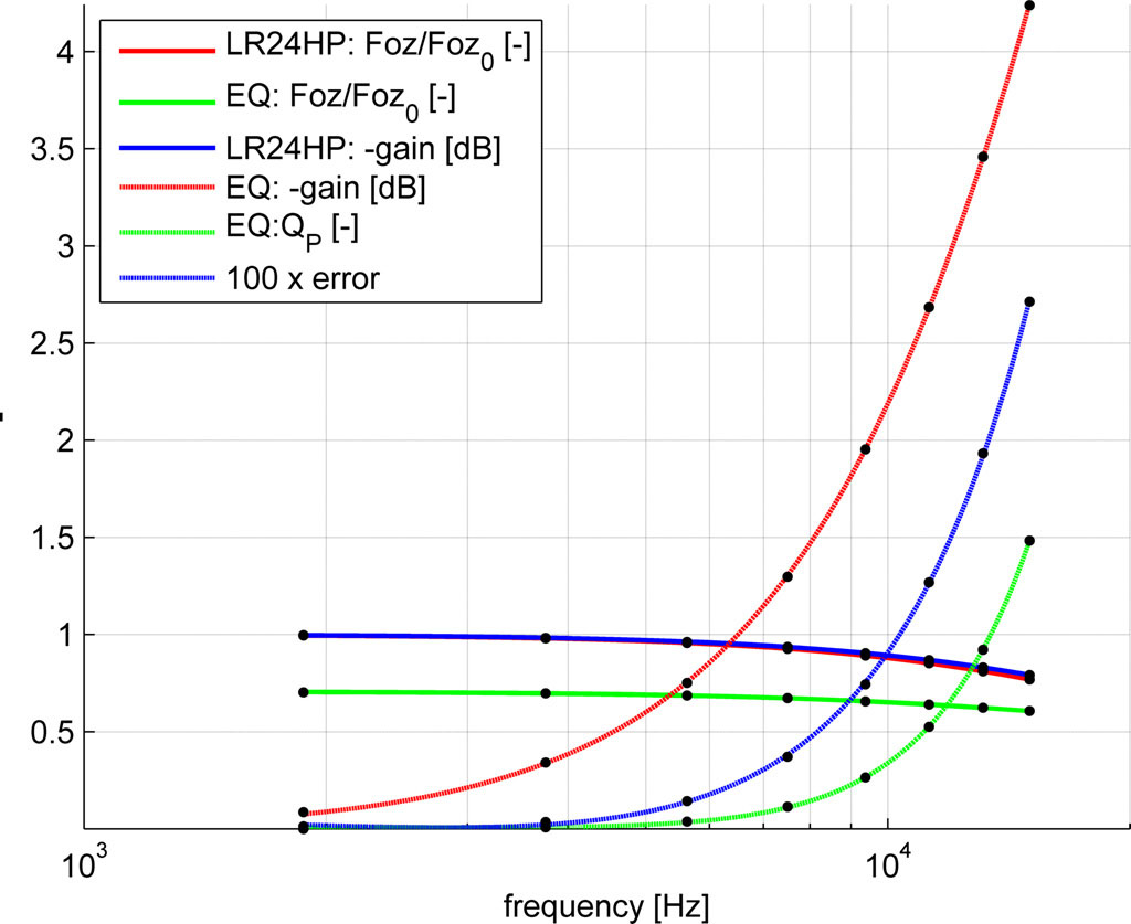
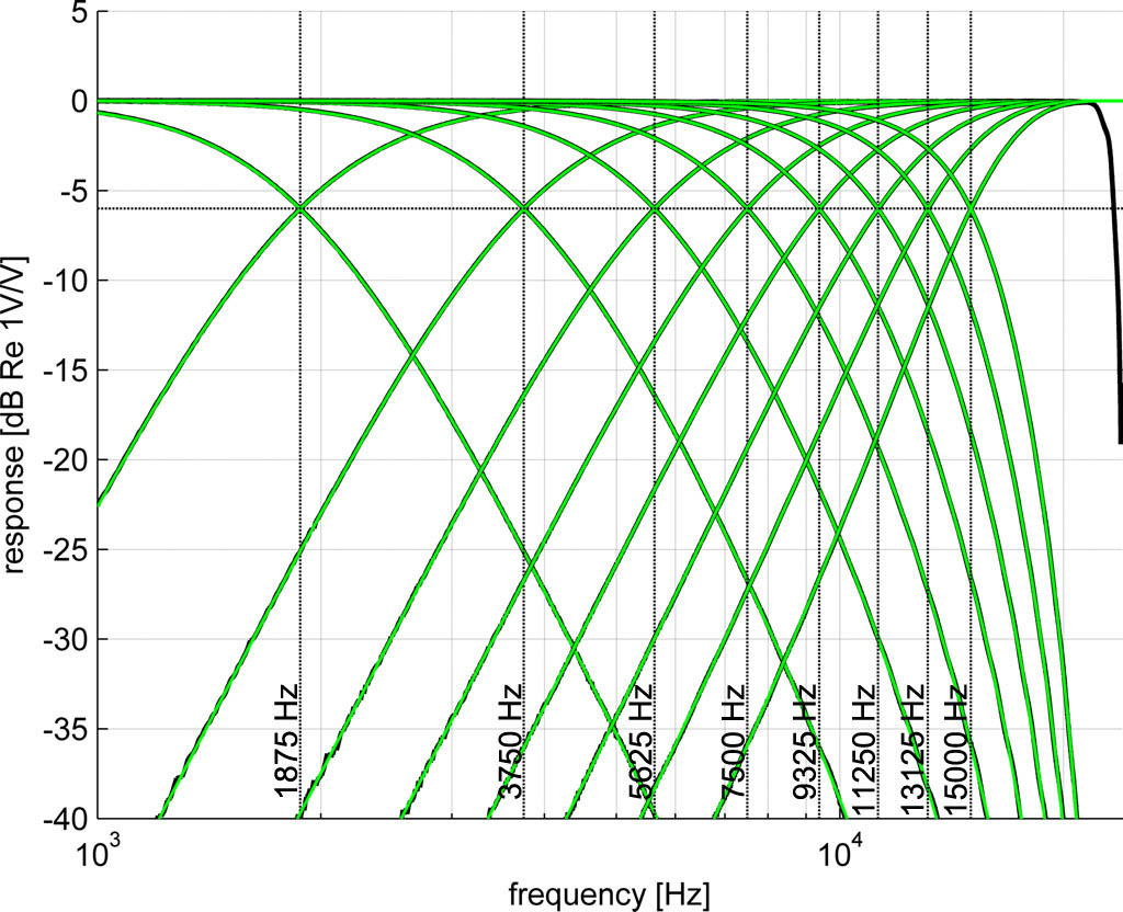
If you plot the settings of both high pass and equalization filter and you’ll notice the filter properties vary quite smoothly as a function of the cross-over frequency; at this point I though I could even generate a small formula to automatically get a reference crossover for a 48 kHz sampling frequency for both the high- and low pass filters.
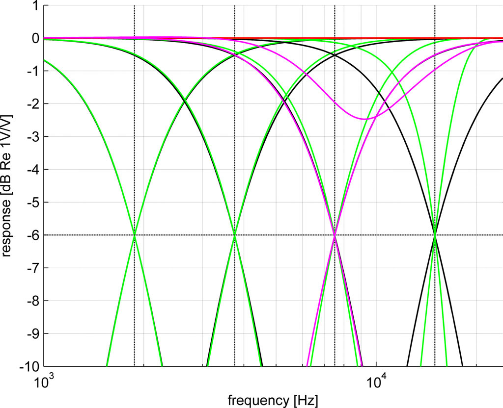
However, when you fit filter components individually on amplitude only—here shown for a 7.5 kHz cross over in magenta—then the filter individual responses looks fine but the summed response is off by 2.5 dB. So, I went into full autist mode and over the course of a few weeks I made a small two-step fitting program to find the coefficients that minimizes the difference between the reference and DSP transfer function.
The first step is a genetic algorithm called NSGA-II that I implemented for our propeller optimization program (work), an approach where a number of function evaluations is performed using some selection of starting values for all parameters relevant within a predetermined box-constrained search range. From the results the best fits are kept and the worst fits are removed. The best fits are then pairwise combined; some parameters are exchanged and some changed a bit (crossover) and then some are randomly changed (mutation), mimicking the process of evaluation. The process is repeated a few times and generally the results improve with each step; until they do not. The optimization was constrained by demanding that the individual filters were always stable (there are criteria that can be easily evaluated); otherwise your response may be good in theory but the results are all static. Unfortunately the process is stochastic, meaning that you won’t find the same result each time you try and not all results are necessarily good.
In step two a Leverberg-Marquard gradient search approach was applied . This second step will continue from the best solution from the GA and homes in on the solution by testing the change in the total error for a change of each variable. The convergence can be slow but after a while you get error progression in the micro dB and then it is time to stop. After some testing running the GA 10 times and the gradient search no more than 2,500 times usually gave the same results for each run.
The combined approach proved to be useful. Some filters using a combination of the same filter types and if they have the same starting value the second step will always fail; the GA does not do that and provides an excellent starting point but not a good end point. I did spend a lot of time narrowing the search ranges manually in order to get it to work properly, learning about “machine learning”.
The animation shows an earlier attempt where each individual stage was fitted on both its phase and amplitude response; later I minimized the error in both the individual and summed amplitude transfer simultaneously and dropped the match with the phase: if the individual and summed amplitude responses are matched well then the phase differences will be matched automatically too. In the end I took the following approach for the entire cross-over that seemed to work well enough
- Simulate the entire cross-over in TINA, an analog filter simulator, exporting the (complex) response for each step of the filter of the Orion and the LX521.
- Pin down the ingredients of all stages of the cross-over for each channel separately.
- Fit the summed response, starting from the lowest frequency stage whereby the highest-frequency contribution was updated and the lower contribution kept constant. Only the lowest LF stage was not affected by the low sampling rate of this particular DSP so it made sense to start there.
- Implement the results in the 2×4 miniDSP and compare the measurement using the program ARTA with the expected response. This is a very use tool using your PCs soundcard’s line in/out to obtain the miniDSPs transfer.
So, this fitting procedure was certainly not a fire & forget exercise. Some stages needed to be fitted only for the response above -10 dB, some need a wider range or a restriction in the frequency range, the number of equalization filters and their search range needed careful attention and so on. For some starting points the second search algorithm would go insane and the calculated filter stability criteria were not always met.
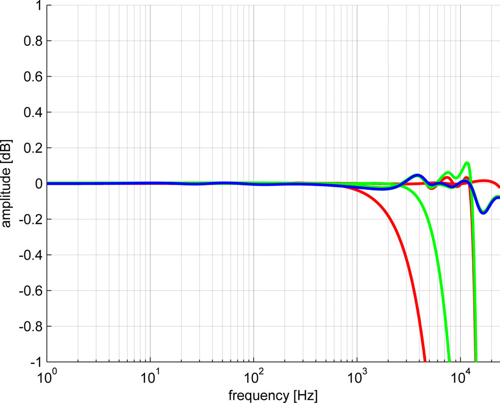
This LX521 was more complicated to fit than the Orion with a few parallel notch filters that I could only fit with some trial & error. It was for these filters that you’d sometimes need a full phase inversion (that was very easily solved by setting a minus in front of the biquad expression). The transfers of the LX521 are proprietary information and cannot be shown , so I show only the error of the DSP implementation in dB. The green line is the individual error for each channel (3 total), the red line the error of adjacent channels and the blue line is the error of all summed channels. While the individual error can be large, these errors occur when the net contribution of that channel is very low as evidenced by the total response. The entire fit is within 0.05 dB except for a small dip at 15 kHz that I left unsolved.
Now, the miniDSPs 2×4 had a bit of a hiss that was not volume dependent. I wasn’t entirely sure how or why this happened, but for five channels I was hopeful that the 2×4 balanced edition would be more silent. I bought five and sold the normal versions. However, these DSPs proved to generate far more noise that was just terrible at the listening position. I read up on chassis grounding for balanced connection, solving pin 1 problems, checking cables, “secret” jumpers on the miniDSP and reading up on the net. Many more people complain about noise from the balanced version and connecting it in as an unbalanced (!) version reduced noise considerably—which was indeed the case—but this was still much more that the normal 2×4 that was not really quiet either. MiniDSP didn’t respond to a support ticket so I decided to forgo the DSP entirely and this entire section was now all for nothing, except for an education experience.
LX521: introduction
LX521: deriving the digital filter
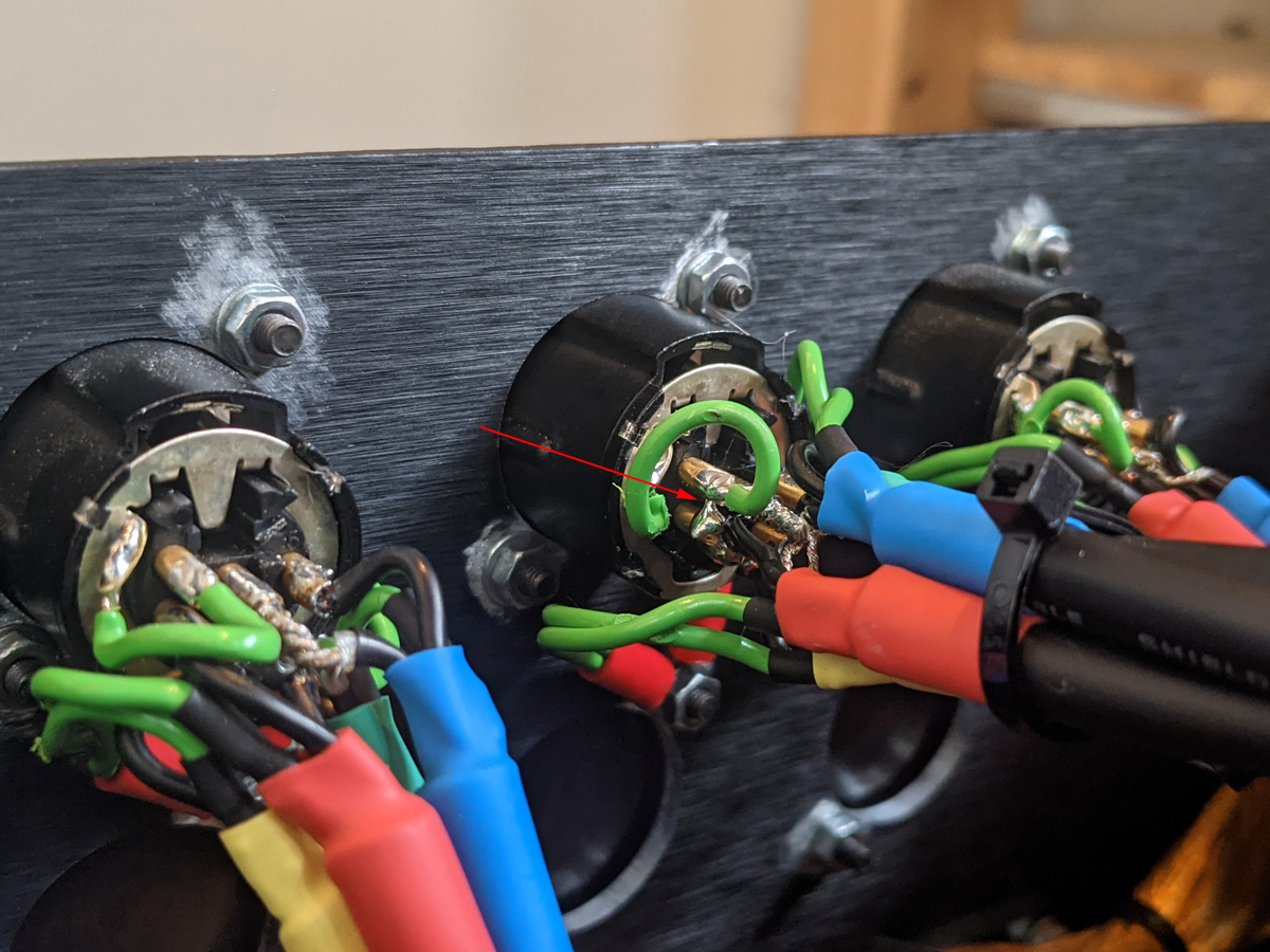
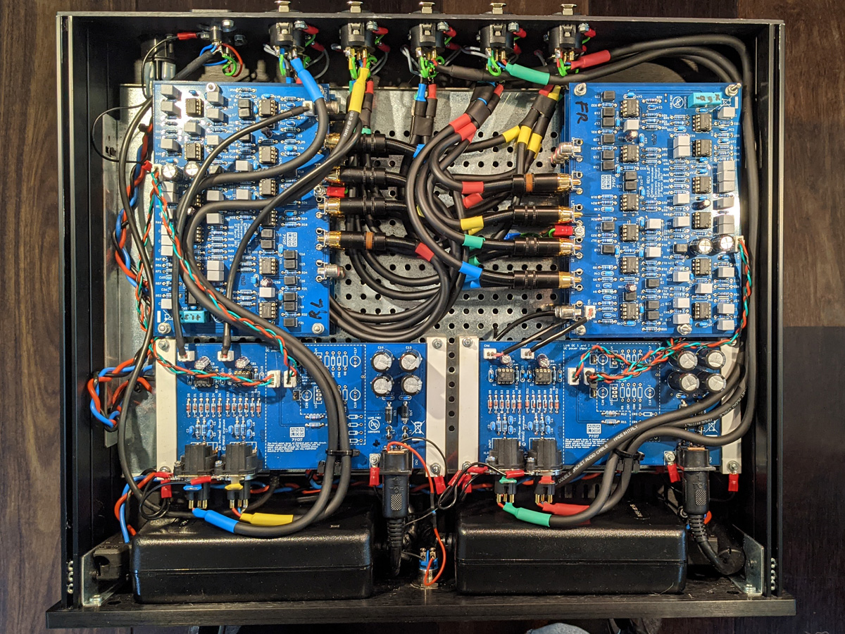
LX521: building the analog filter
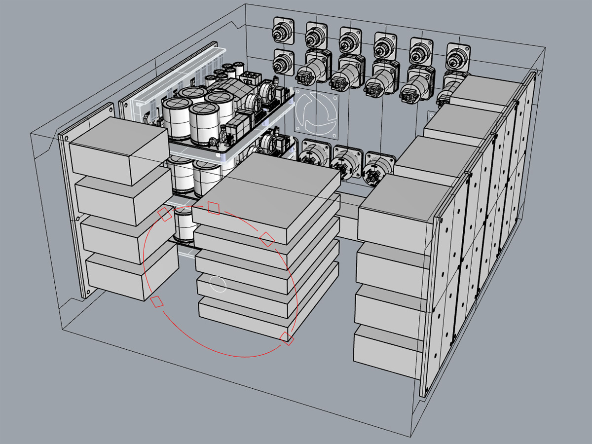
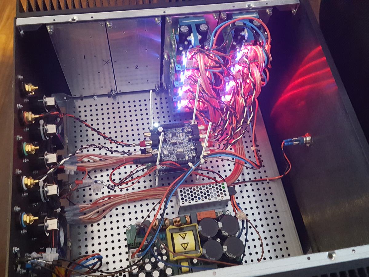
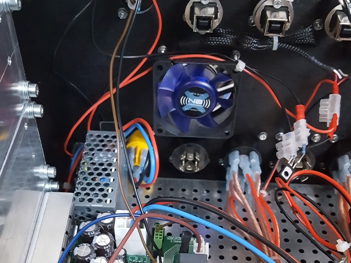
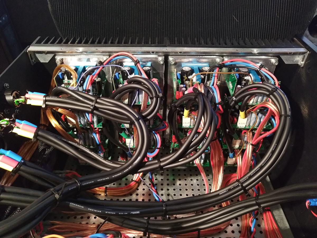
LX521: building the power amp
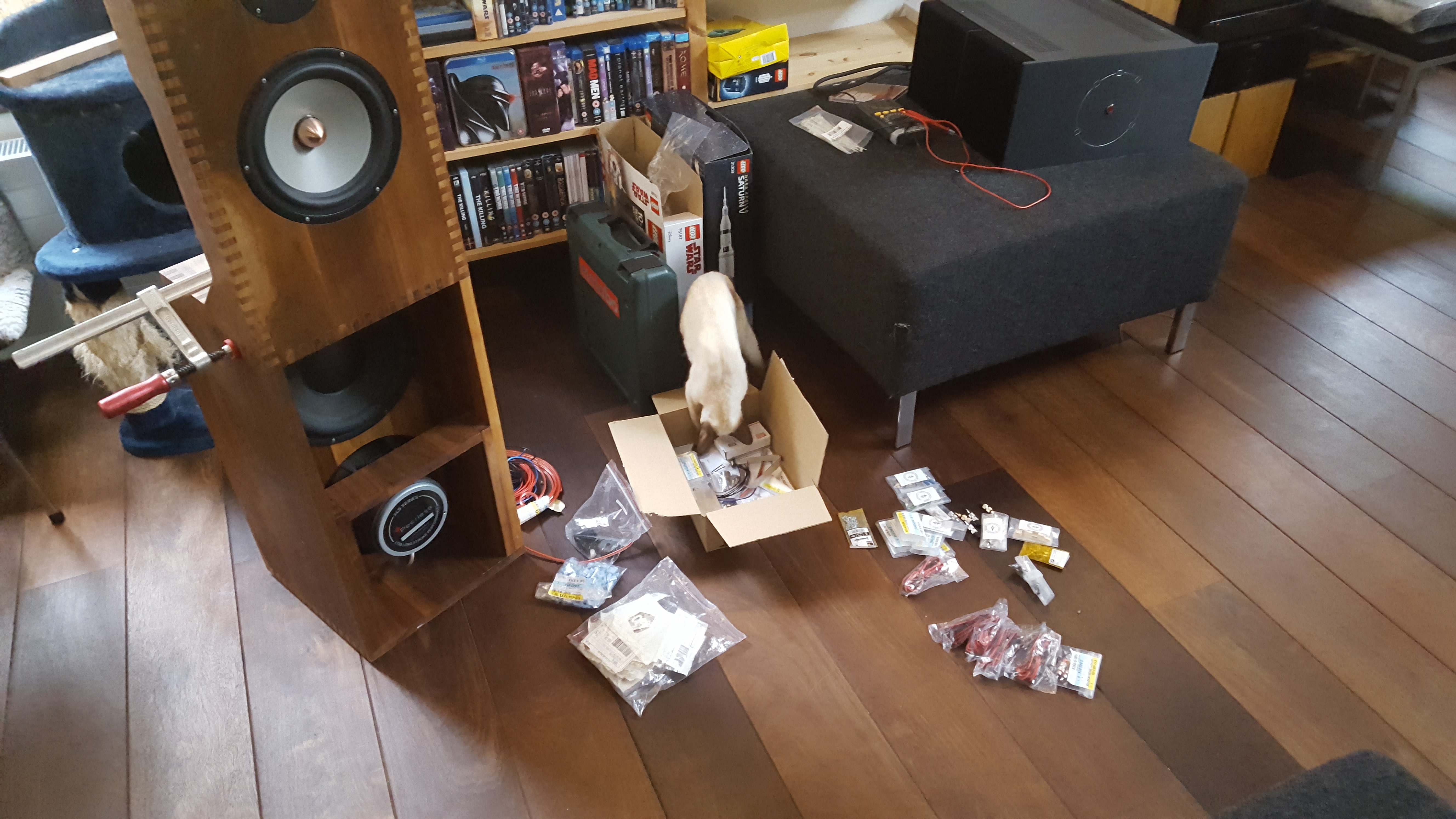
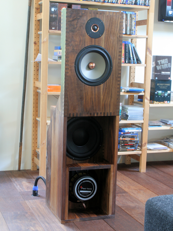
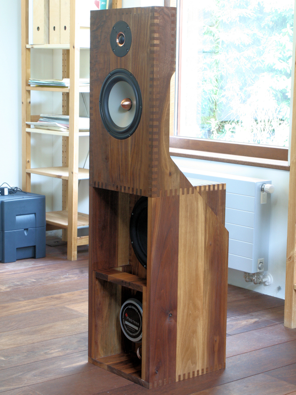
LX521: building the speaker
LX521: results