With special thanks to Sean Carroll and Frank Allen for the discussions and additions.
The exact layout of the boats aboard HMS Hood in 1941 is frequently-asked question. My list is (currently (*))
Many sources will claim that HMS Hood in 1941 was fitted with three 35 ft FMBs —one of which was an admiral’s barge fitted earlier in 1940—but now I believe that this third fast motor boat was never fitted and HMS Hood sank with one of her 50ft Steam Pinnace’s still on board. The most direct evidence follows from an image from an undisclosed 1941 album showing the pinnace more clearly in the far background but I can make a very good case (or so I hope) with public material. One other difference is a 2nd 16 ft dingy that is easily spotted on photographs.
After 1940 Hood no longer carried her 5.5 inch guns and after the 1941 Rosyth refit a few changes were introduced that make it fairly straightforward to date an image as either 1940 or 1941
- Torpedo lookout removed from foremast
- Type 284 gunnery radar fitted on the top DCT
- Fore topmast removed and aerial spreader mounted on a frame
- Type 279M fitted to main mast
- HF/DF office on main mast starfish removed (small cabinet present)
- 50 ft Steam Pinnaces replaced by 35 ft FMBs
Normally we’d use the presence or absence of the 35 ft FMB to date an image, but as the port side boat was never fitted we should no longer do that. Some of the images below are cropped, not showing the clearest indicators that are often in frame (i.e., removal of the HF/DF office on the main mast and torpedo lookout from the foremast), but you can find them in various publications if you need to be sure.
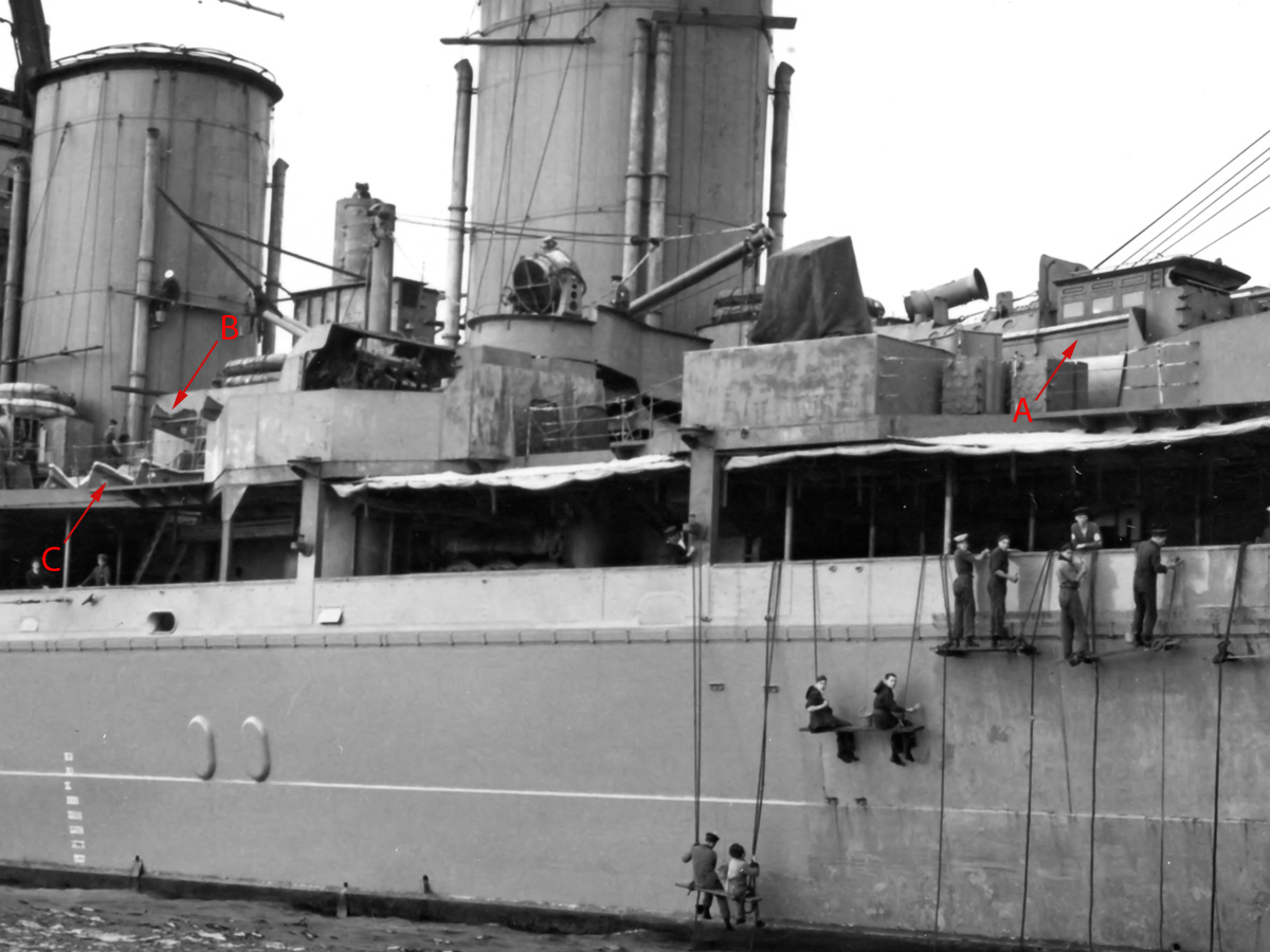
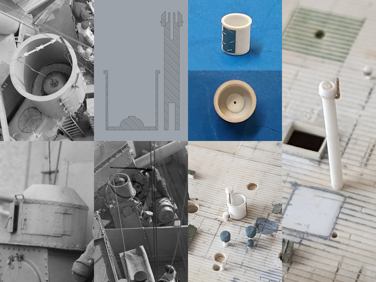
First we’ll have a look at the boat deck prior to 1940. Hood carried (A) 2 x 50 ft Steam Pinnaces and (B) 1 x 45ft Admiral’s Barge; the latter has an overhanging stern and its overall length is almost the same as the 50 ft Steam Pinnace.
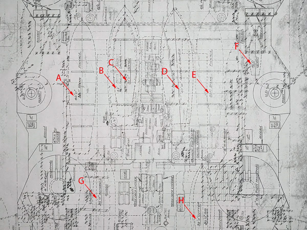
On the original plans from 1940 we see—from left to right—
- 45ft Admiral’s Barge
- 45 ft Motor Launch
- 32 ft Cutter
- 42 ft Motor Launch
- 50 ft Steam Pinnace
- 16 ft dingy,
- 35 ft FMB (Admirals Barge)
- 30 ft gig stored on top of the second 32 ft Cutter
For those people who are detail-minded, note that the 42 ft Motor Launch is placed at a slightly inboard angle. Note that with the new 35 ft FMB (Admirals Barge) that the 45ft Admiral’s Barge is now simply referred to as a pinnace.
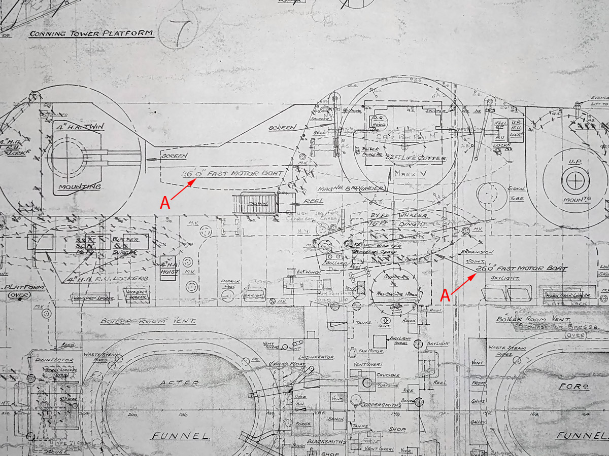
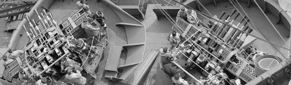
Near the port side pompom many boat outlines are visible and many of them are crossed out, except for (A) 2 x 25 ft FMB. Note that the more forward boat is also placed at an angle
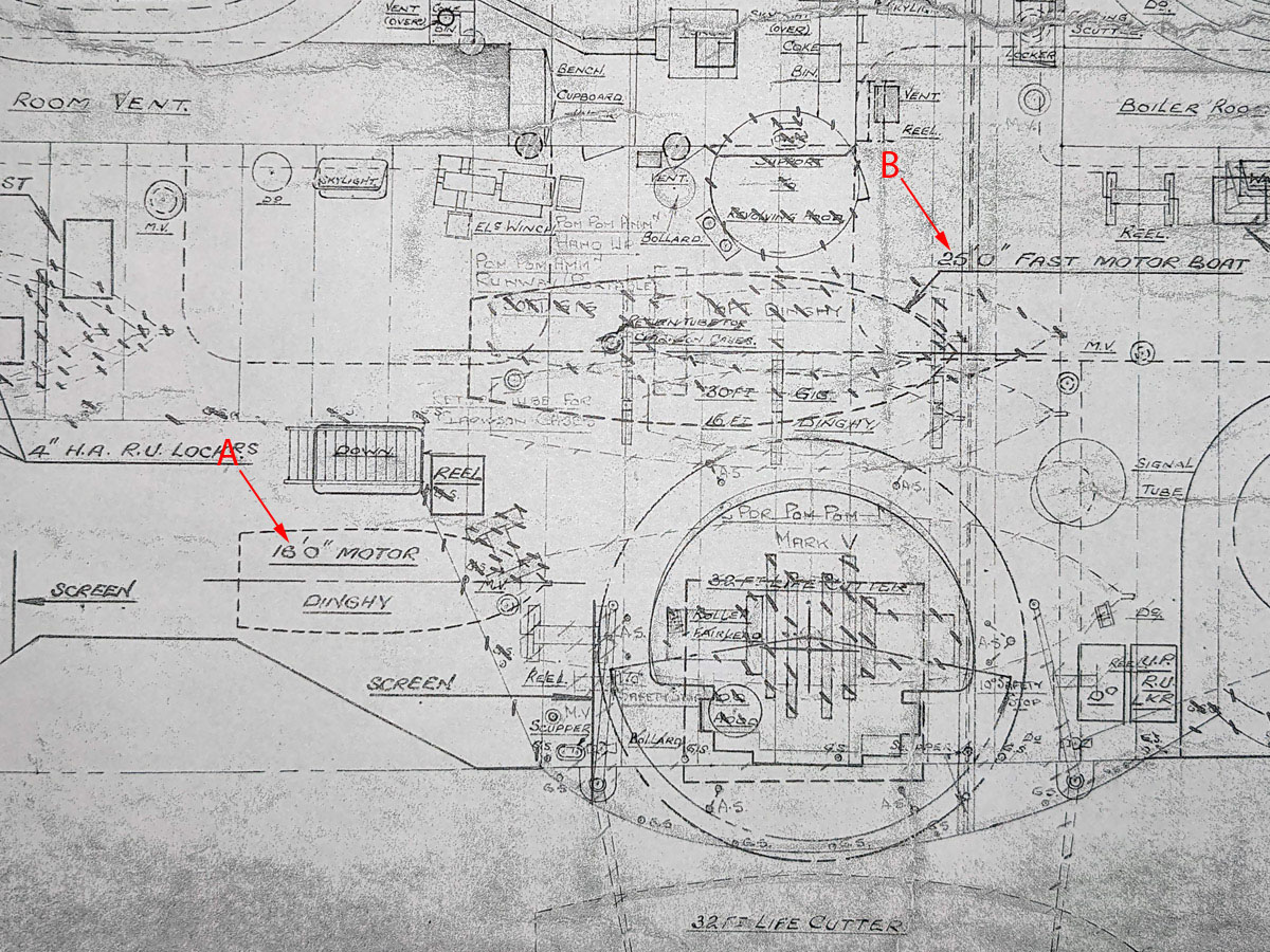
Near the starboard pompom the situation is largely the same with many older boat locations crossed out and only (A) 16 ft FMB and (B) 25 ft FMB .
Two 16ft dinghy’s in cradles on either side of the DF platform are not on this drawing.
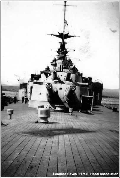
In this well known image from 1940 we see the (A) 45ft Steam Pinnace , (B) the cradle for the 16ft dingy—ignorant that it is not on the plans—and (C) the crutches for the 25 ft FMB.
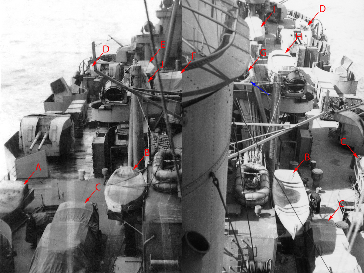
When we compare the drawings with these image taken from 1941 we see that little has changed (left image courtesy HMS Hood organization, right own collection).
- 16 ft FMB,
- 2x 16ft dinghy’s in cradles,
- 3x 25 ft FMBs ,
- 2x 27 ft Whaler,
- (presumably) 30 ft Gig/32 ft Cutter combination,
- 42 ft Motor Launch
- 45 ft Motor Launch (note the 2nd rubber at the blue arrow),
- 35 ft FMB
- 35 ft FMB (Admirals Barge)
- our suspected 50 ft Steam Pinnace.
While these images visually confirm most boats, it’s not clear from the left view what type of boat is actually at J.
I cannot confirm the presence of the 30ft gig or 32 ft Cutter on top the the other 32 ft Cutter and 45 ft Motor Launch, respectively. That is, on some pics I can see something on top of the motor launch but not enough to make out what, but it’s fair to assume that the 1940 plans still holds; both the 42 ft Motor Launch and 45 ft Motor Launch can be spotted in various other 1941 photographs (not presented).
There is circumstantial evidence in Bruce Taylor’s highly recommended book, pp 210, with a summary of the refit by Philip Bucket dated the 6th of March 1941 that reads:
“[…] The second picket boat has been replaced by a 35-foot motor-boat”
Taylor adds a footnote that both steam pickets were replaced, but the above is oddly specific. This could well mean that first one boat was removed and then another, but it may well mean that only one steam pinnace was removed which is not contradicting my 50 ft Steam Pinnace theory. We already noticed that the 45ft Admiral’s Barge was demoted to the rank of ordinary Steam Pinnace.
Furthermore, in the aftermath of HMS Hood’s destruction, Robert Tilburn responds to Board on Inquiry on how the fire spread on the boat deck:
Could you say exactly were the fire seemed to start?
No, it was somewhere between L.I. and the U.P. mounting.
Which way did it seem to spread?
It did not seem to spread at all. At kept on blazing while we were in action but it did not seem to spread to the picket boat or anywhere else, though I cannot say definitively weather the picket boat took fire or not. Anyway, it did not move [illegible] before L.I. 4″ mounting.
Now, L. I. is the portside, most forward 4″ gun, and, Tilburn was also sheltering on the port side when Hood was hit. That would put the fire near the 35 ft FMB.
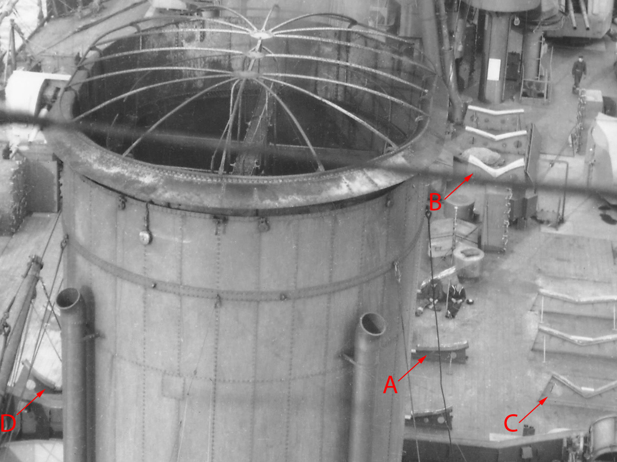
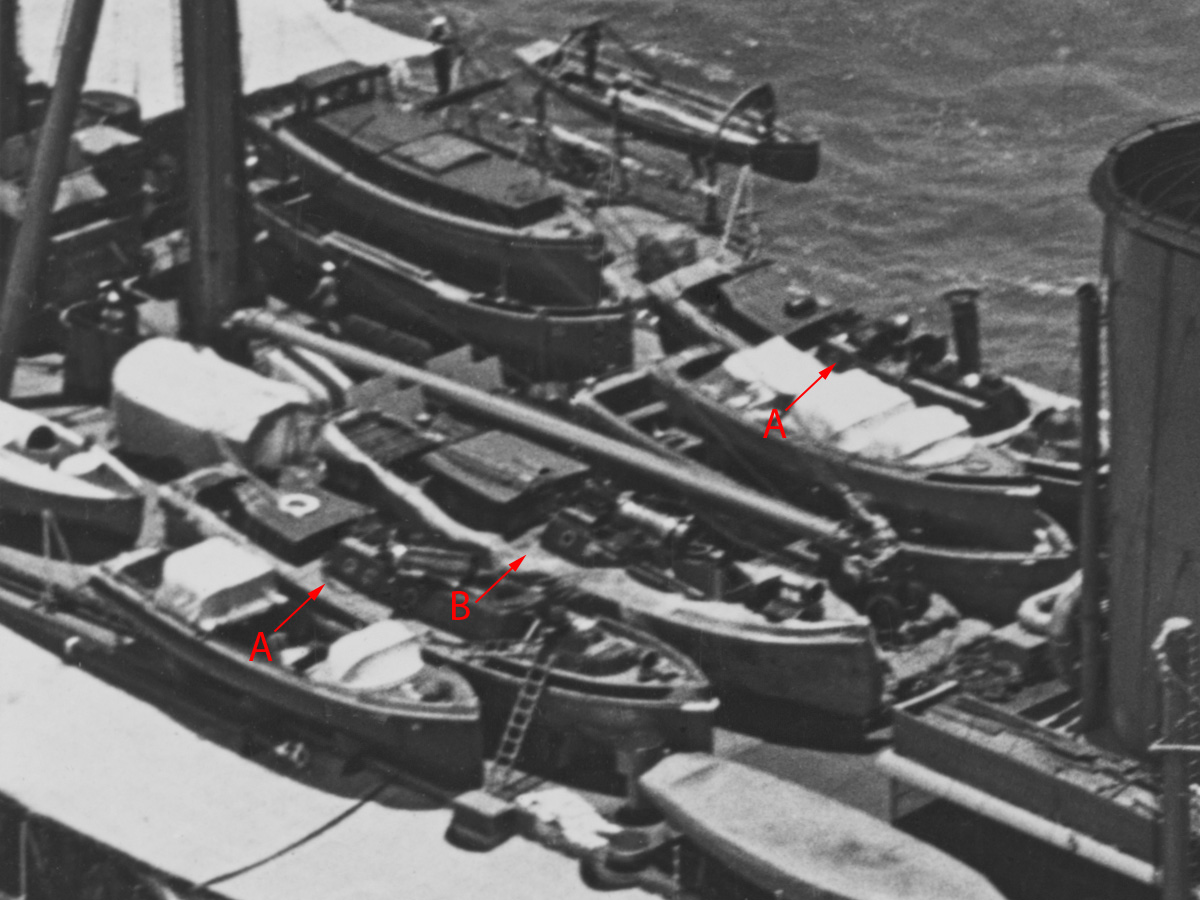
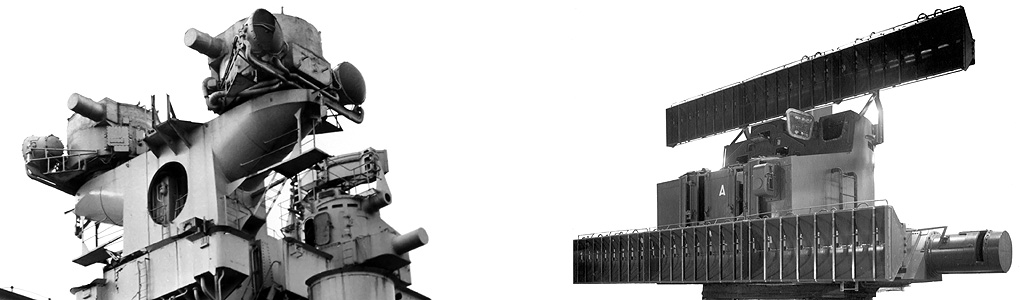
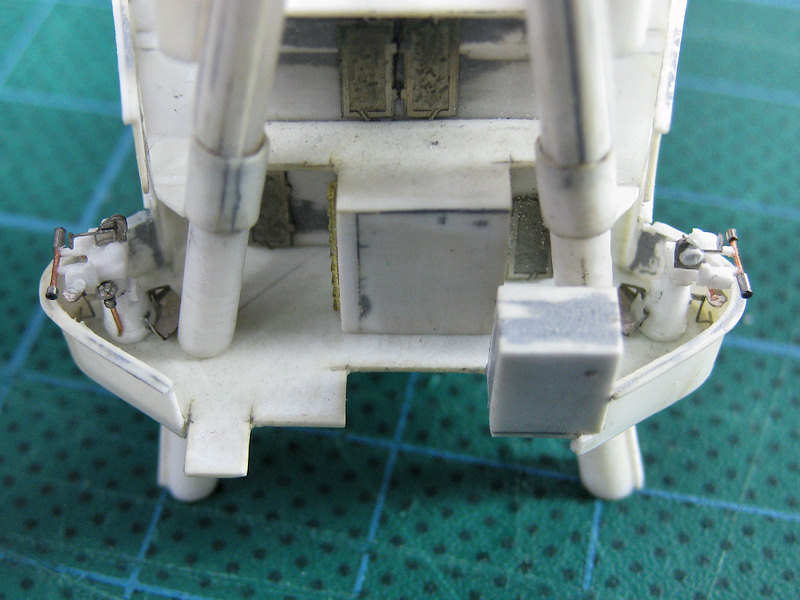
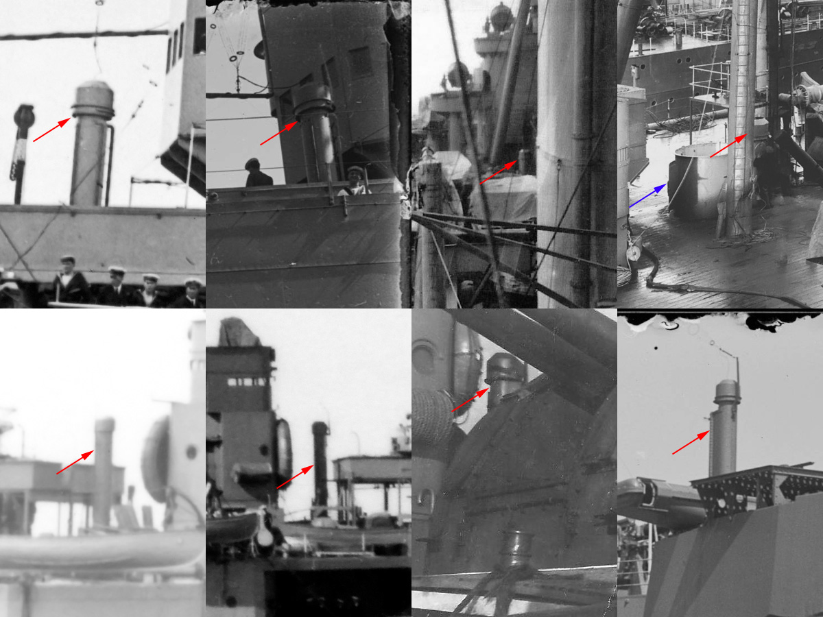
When we take a closer look at the boat deck we see the (A) crutches of the 45 ft Motor Launch and the V-shaped crutches of (B) the 35 ft FMB (Admirals Barge) and (C) 35 ft FMB that share the same hull. The boat crutches at (D) are not those of a V-shaped hull. This issue was also raised by Flyhawk when we (I and the Hood association) were assisting them with their 1:700 kit—just to give you an idea how well they were looking at the available material—but we could only offer cognitive dissonance at that time. Of course, on this 1941 image there simply is no third 35 ft FMB at that position as the 50 ft Steam Pinnace was still on board (well, not in this particular image, but, it’s close).
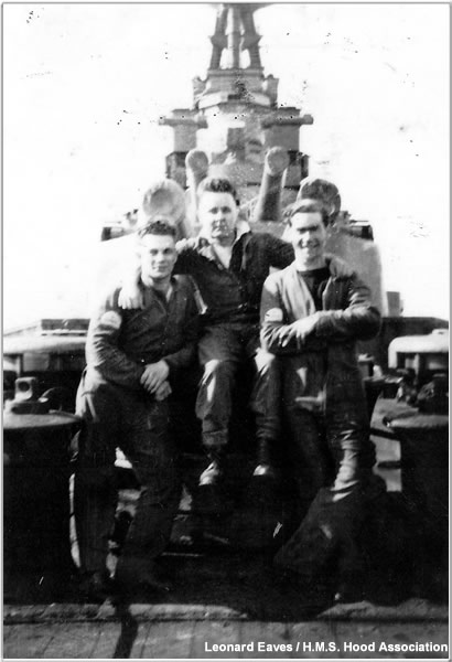
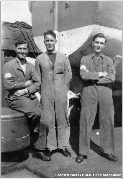
There is also a collection of images at the Hood association by Leonard Eaves that are dated as either 1940 or 1941. Those that are dated are all placed firmly in 1941 except a few. Some images can be pinned to 1941:
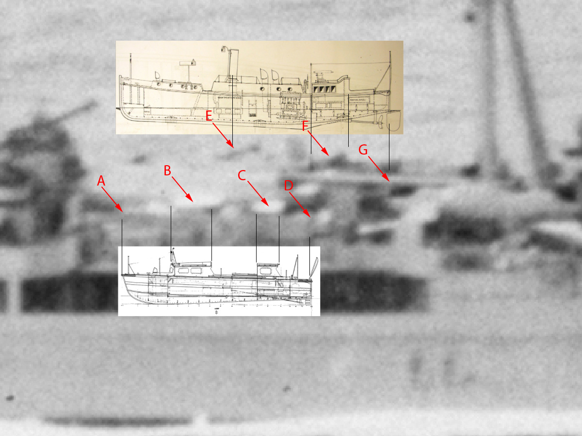
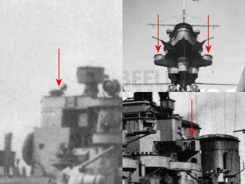
Now look closely at this photograph of HMS Hood dated the 22nd of May 1941, mere days before her loss. I scaled the image to roughly Hood’s length and first added the 35 ft FMB to scale. We do not have full resolution but I can make out (A) the bow, (B) the forward cabin, (C) the aft cabin, and (D) its stern; it’s not exact but matches well enough. I did the same with the 50 ft Steam Pinnace. I see (E) a funnel folded down, (F) the cabin with its characteristic upwards sweep, and (G) the stern and steep buttocks. While vague, what we do see matches exactly with what you would expect when a 50 ft Steam Pinnace were in that position.
* Update 09/05/2022 Corrected links to correct 32 ft Cutter.
