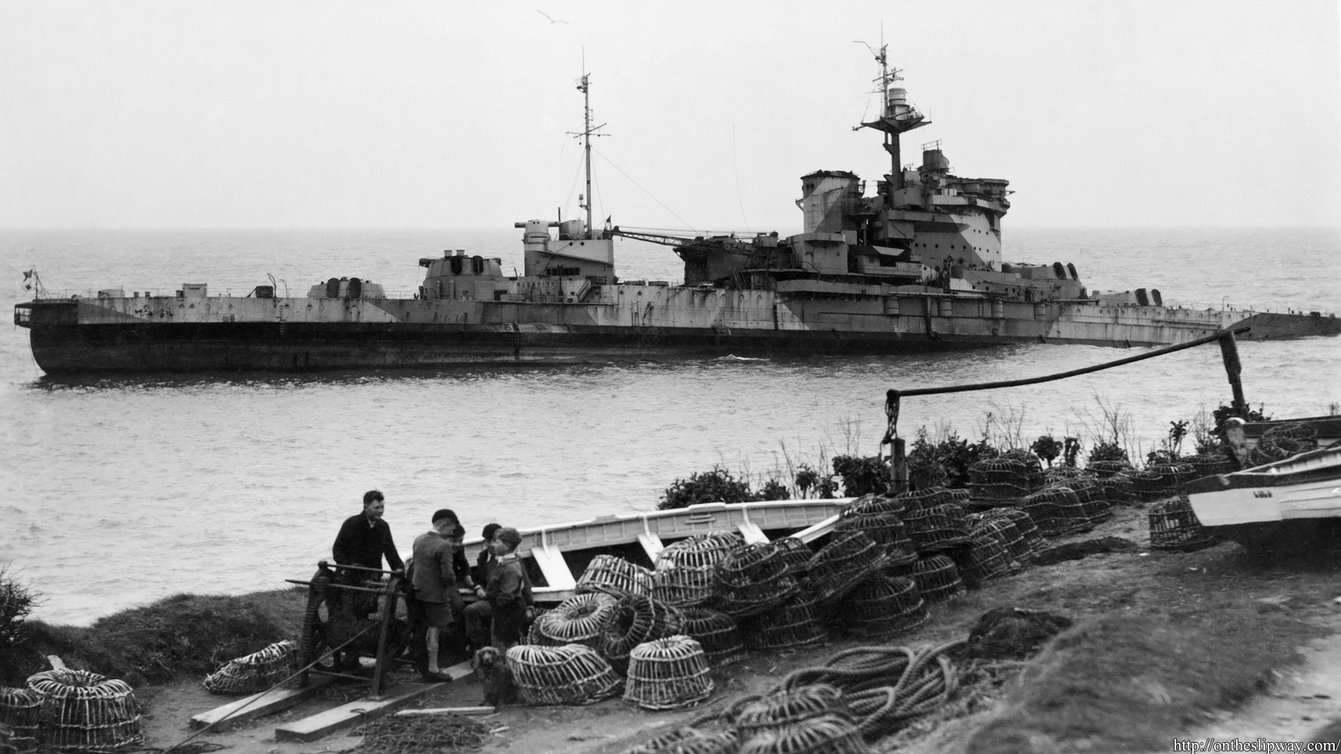
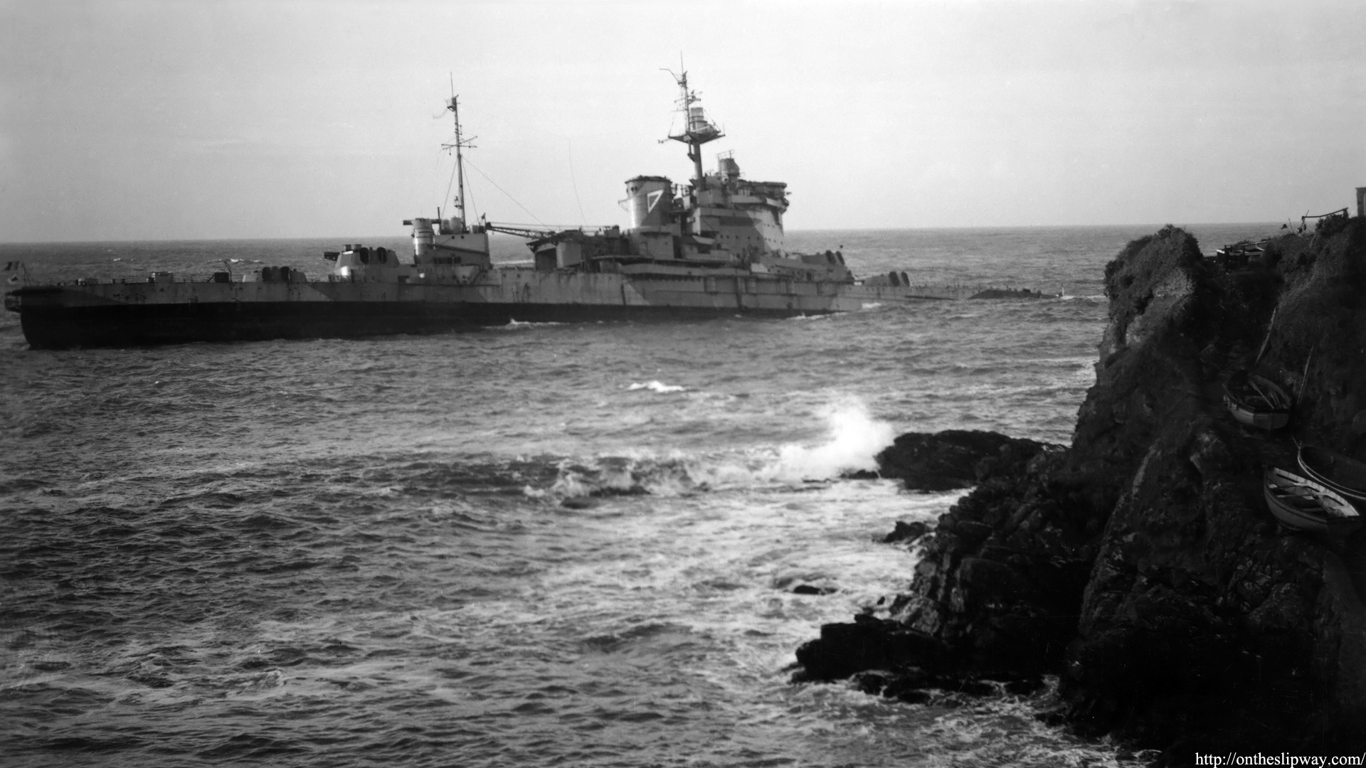
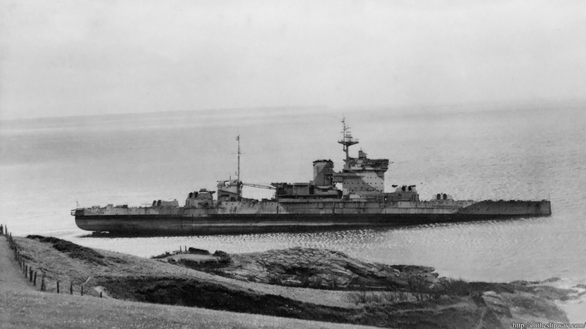
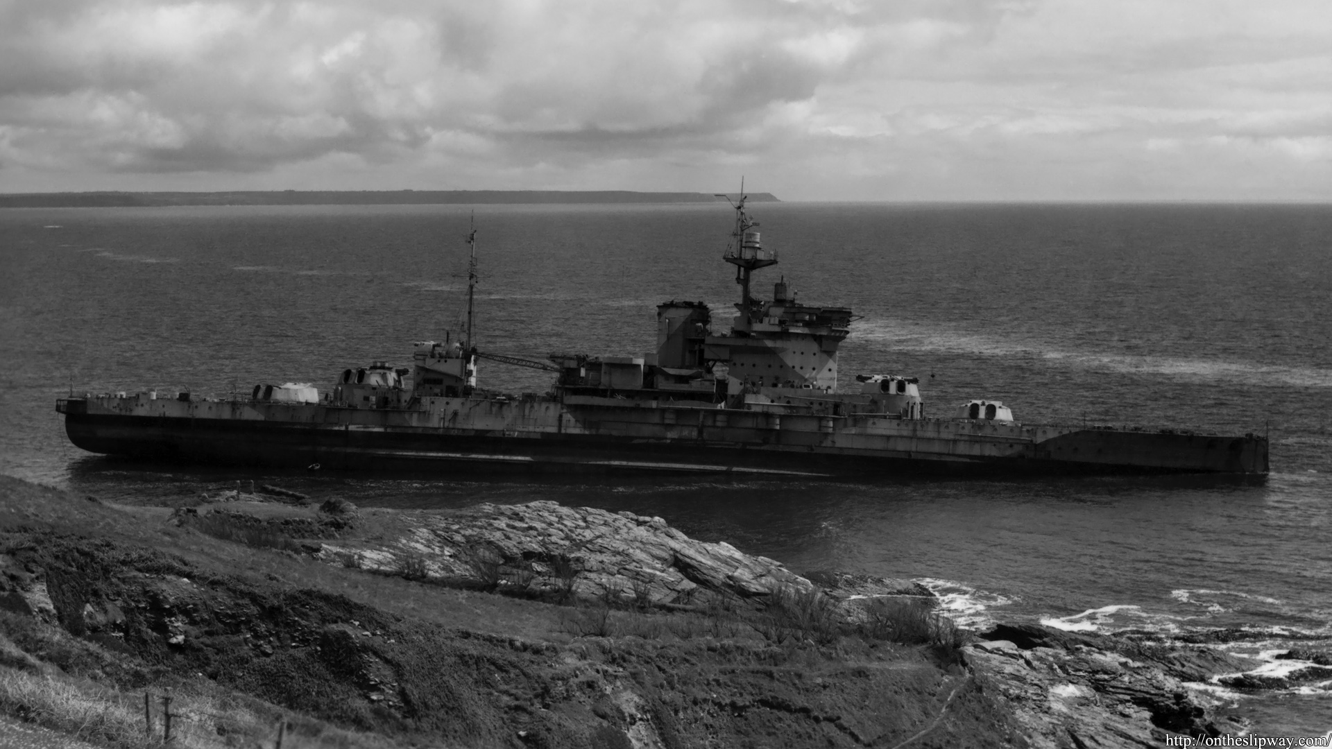
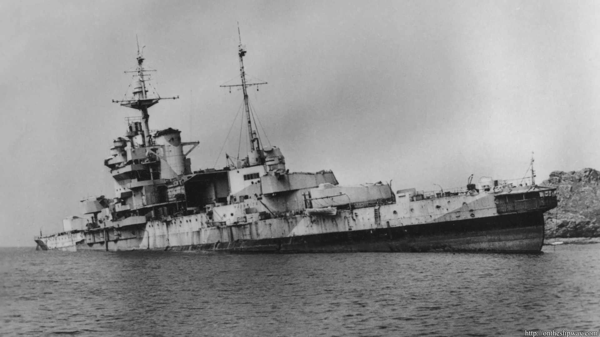
Following my earlier post of Warspite (1937), a series of images of Warspite after decommissioning and running aground at Prussia Cove. Finding new images is quite difficult and auction prices go up really quickly, but I hope to add more.
Update: 27/11/22 Image #5, marked buoy picture.
Update: 22/03/24 Image #6, port side shot (unsharp, might be nice for reference).
Update: 23/05/24 Image #7
There’s a small line running from the bridge towards A-turret carrying a marker ball. I always remove blemishes from scans and one may inadvertently remove something in error; the postcard above was damaged at the precise location of the ball; the line remains visible and the ball is still there.
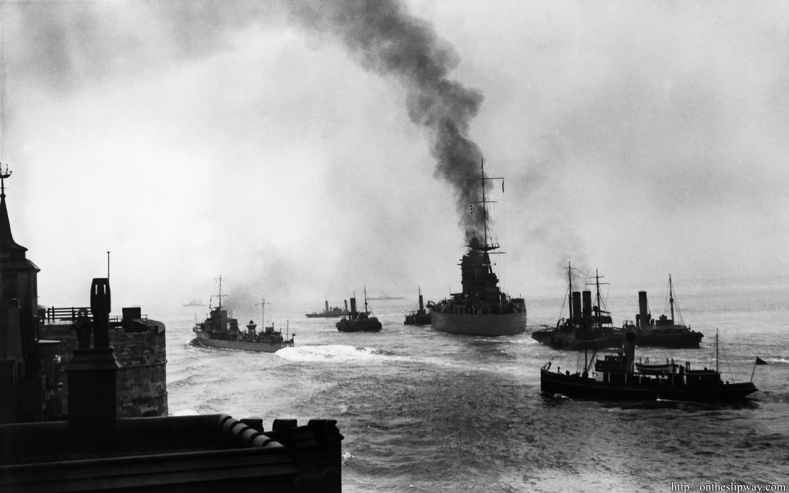
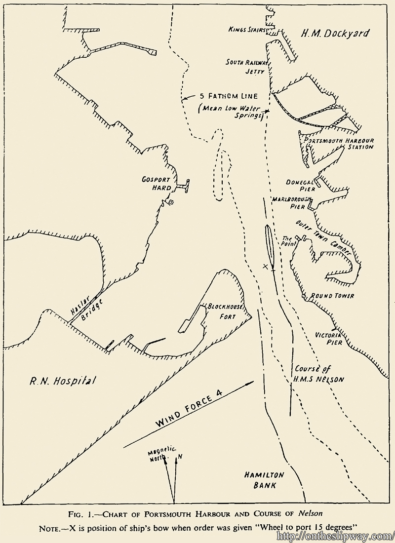
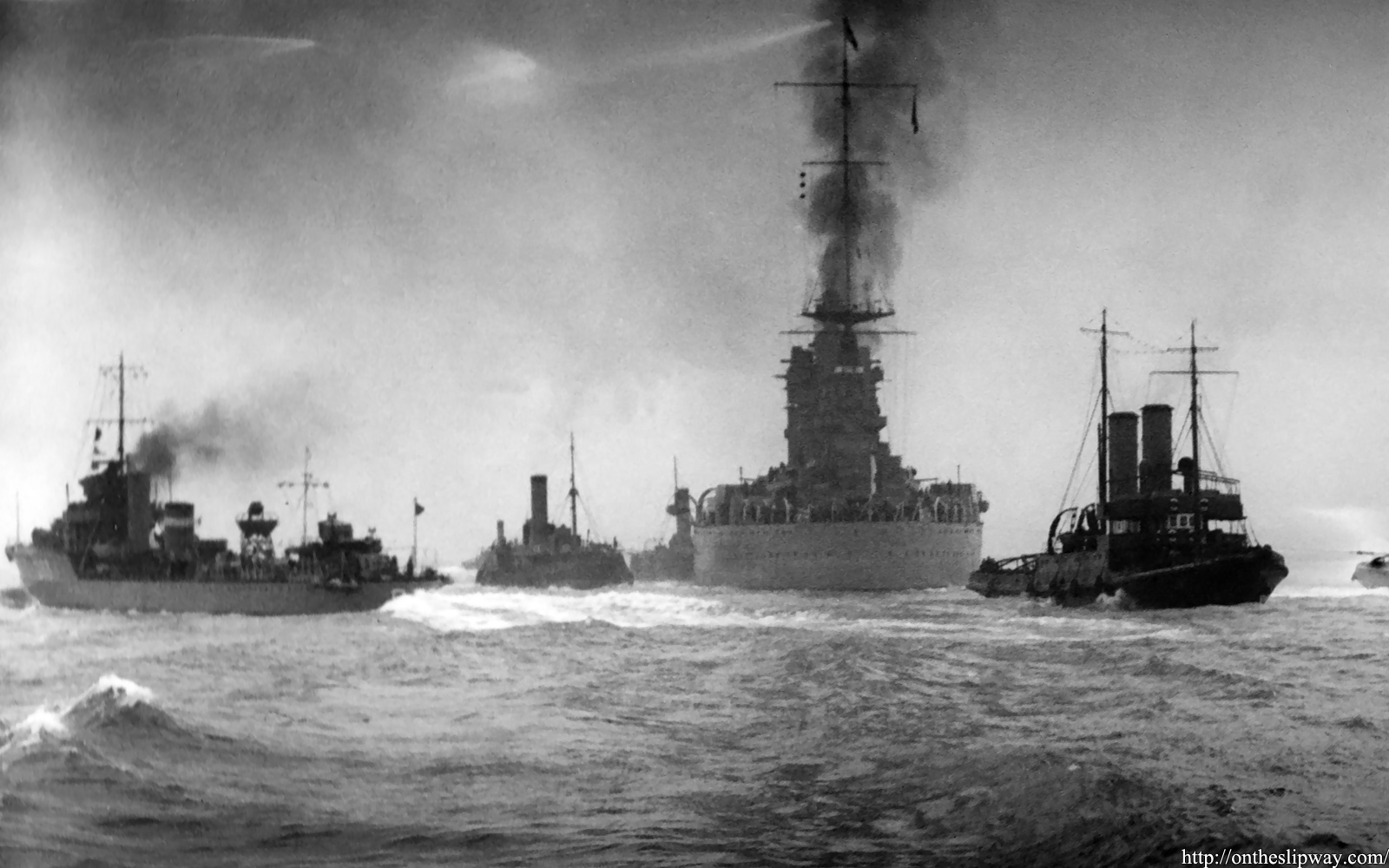
On January 12th 1934, HMS Nelson was leaving the Portsmouth harbour entrance at a speed of 15.5kts assisted by three tugs. That is, the rpm of the propellers was set to an equivalent speed of 15.5kts but by the combined effect of shallow water and a following current of about 1-1.5 kts, her actual speed over ground was estimated by tracking fixed positions on land at 7-9kts. As she was about to pass Blockhouse Fort speed was ordered to reduce to 12 knots, the tow of one tug was parted and she was ordered to wheel to port by 15 degrees. Before her rudder execute she was close the east embankment; shortly after Nelson started steering to starboard—against her rudder—and proceeded about 2.5 lengths before grounding herself on Hamilton bank on the opposite side of the channel.
Fuel and shells were off-loaded, the anchor lowered in a lighter and shoal removed by a dredger; destroyers were ordered to pass her at 20 knots hoping the wash would raise her. It was even attempted to free her by having the crew jumping in unison on the quarterdeck for about an hour. Nelson would be refloated by the next tide. She suffered no physical damage and soon continued with her spring cruise, but the entire affair must have been an embarrassment for the flagship of the Royal navy, immovable for all to see and well captured by onlookers on nearby Southsea beach. The irony of HMS Nelson hitting a bank called Hamilton was impossible to miss by the British press.
It may appear a trivial navigation mistake that was initially attributed to wind conditions, but as with all things hydrodynamic—especially in shallow water— the matter is more complex than it appears. I found a paper in our archives by Gawn (1950) describing follow-up studies explaining what had happened. A series of model tests were performed at the Admiralty Experiment Works at Haslar—opposite to Portsmouth—starting with a small unpropelled 4ft model in a model of the channel; the mass of the model and mass distribution were set to the relevant deep draft conditions as for the ship. These tests were performed with the model in the centre of the channel and various offsets to east and west, at speeds from 7 to 15 knots. The model followed the channel when sailing through the centre with a slight turn to port and responding to the rudder favourably. When the model was more towards the east side of the channel—as was the case on the 12th of January—the model turned to starboard for all observed speeds even with the rudder fully to port; a speed less than 7 knots and a rudder angle of about 20 degrees was required to avoid grounding. When the model was on the opposite side of the channel towards the West the model turned to port, though not as strongly as on the East side. Increasing the depth in the channel reduced to effect of steering against the rudder.
Reproduced from Gawn (1950)
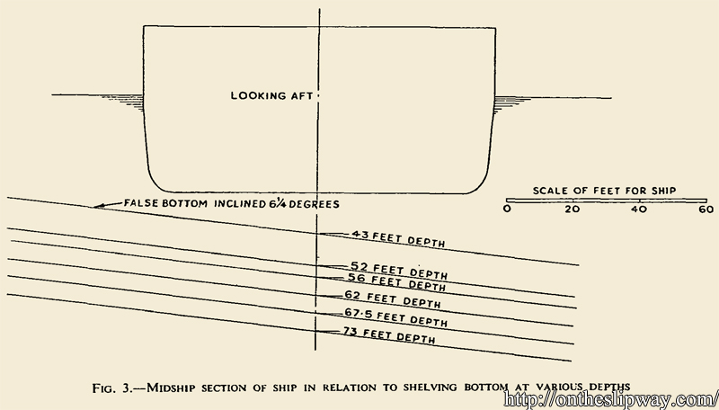
A second series of test was performed with a medium-sized self-propelled model of 16ft at the large No2 ship tank. A false bottom at a 6.25 degree inclination was added to the tank. The model was tested at speeds of 6 to 14 knots and the rudder angle was set such that the model kept a course parallel to the bank.
Reproduced from Gawn (1950)
From these tests it followed that the rudder angle needed to keep a course parallel to the near bank increased with both higher speed or lower water depth. At the depth and speed corresponding to the conditions in Portsmouth harbour a rudder angle of 35 degrees was not sufficient to avoid the model from veering away from the shallow region. Using a rudder about 20% larger in area would not have helped in avoiding Nelson grounding.
From these test it was concluded that Nelson sailed too much off centre in the channel at a speed at which grounding on the opposite side could not be avoided; an explanation rear-admiral Macnamara—captain when the incident happened—regretted not having sooner. He also commented that while the Nelsons were reported to have good steering properties that he found them to handle badly especially in shallow water or wind, although this opinion was not shared by other officers. Mr Stanley, who worked on the design of the Nelsons as an assistant director of naval construction and who was also aboard when Nelson grounded, was of the opinion that the grounding was not to be accounted for by any defect or deficiencies in the steering qualities of the ship; in fact, the Nelsons were known to handle better that the battleships of either the Queen Elizabeth or R-class.
The cause of Nelson’s course instability is bank suction; in the restricted channel the flow cannot go under the bottom freely and the presence of the wall causes an asymmetry in the flow; the bow experiences a small apparent lift angle forcing it outward, while the stern experiences a low pressure region on the bank side pulling the ship in; a ship will typically yaw and then move away from the bank. The rudder must be moved towards the near bank to stay the course and then the ship can sail at a drift angle in a channel.
Nelson’s model test also showed the thrust of the port propeller was about twice that of the starboard propeller as her stern swung towards the near bank. From a more modern analysis we find that the flow in shallow water runs under the keel from the outboard towards inboard side and may even separate running over the skeg resulting in a region of ‘dead’ water. The inner propeller operates more as in bollard-pull conditions where propellers produce more thrust, forcing an even lower pressure on the stern making the situation worse (the contribution of the force imbalance to the yaw moment between the two propellers is most likely very small).
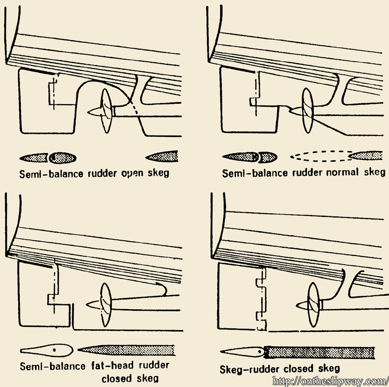
Reproduced from Vossnack (1979)
The rudder arrangement of the Nelsons is a semi-balance rudder on an open skeg; these rudders offer good steering properties at high speed with relatively small turning circles and low resistance but are (now) known for their poor steering properties at low speed, particularly in shallow water and more so when their shaft lines diverge when running aft; modern twin-screws container ships with a semi-balanced rudder were reported to hit the side walls of the Suez canal (Vossnack, 1979). A closed skeg may have been a better choice; however, a twin screw-twin rudder arrangement that allows for the propeller race over the rudder offers far better steering properties as the rudder’s effectiveness increases with the flow speed squared; it remains effective in the slipstream even at low ship speeds. It comes as no surprise that increasing Nelsons rudder by 20% had no appreciable effect. Placing the rudder in the slipstream does incur a resistance penalty, partially offset by increased propulsion efficiency as the rudder acts as a preswirl stator recovering rotational energy losses by the propeller.
A news clip can be found here
A wonderful serious of aerial shots of Nelson Aground are held by de Daily Herald archive and can be viewed via the image thievery website Getty
Consulted sources
Brix, Manoeuvring Technical Manual, Seehafen Verlag, ISBN 3-87743-902-0 Hamburg 1993
Burt, R.A., British Battleships 1019-1945, ISBN 9780 1 84832 130 4, Seaforth Publishing, 1993
Garthune, R.S., Rosenberg, D., Cafiero, D, & Olson, C.R., , The performance of model ships in restricted channels in relation to the design of a ship canal, David W. Taylor Model Basin report 601, 1948
Gawn, R.W.L., Steering and propulsion of HMS Nelson in a restricted channel, Transactions INA, volg 92, pp82-106, 1950
Hoydonck, W., van, Toxopeus, S., Eloot, K. Bhawsinka, K. Queutey, P. & Visonnea, M., Bank effects for KVLCC2, J. of Marine Science and Technology 24(9), 2015
McNeil, Nelson & Rodney 1927-1949 The big battleships, Maritime Books, 2005
Vossnack, E., Good steering properties of container ships, the Motor Ship, November 1979
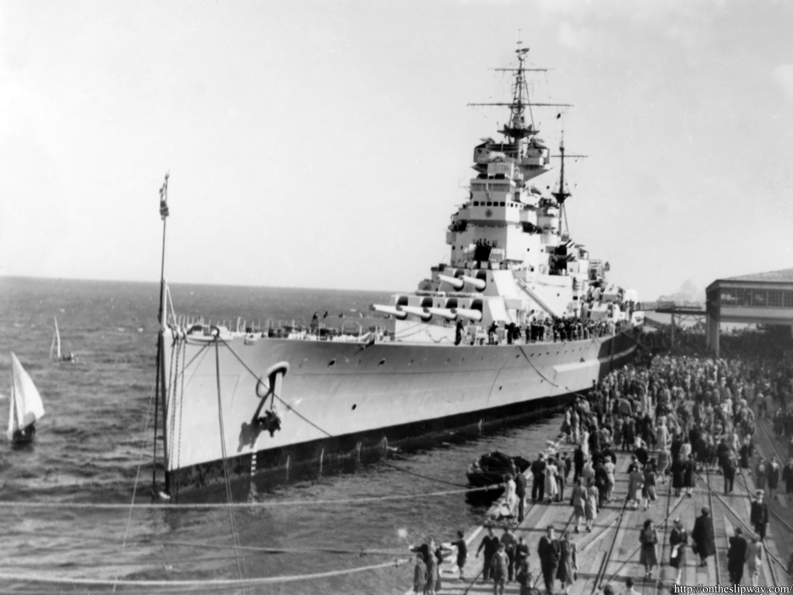
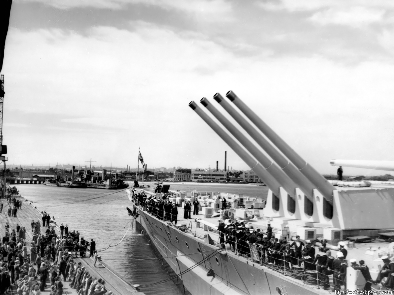
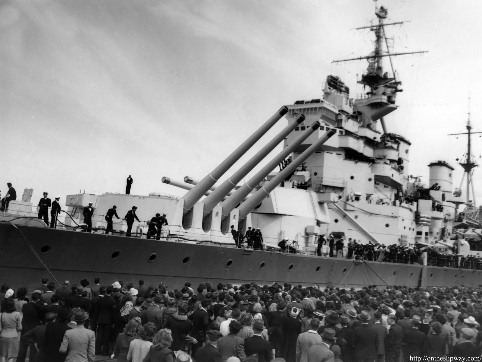
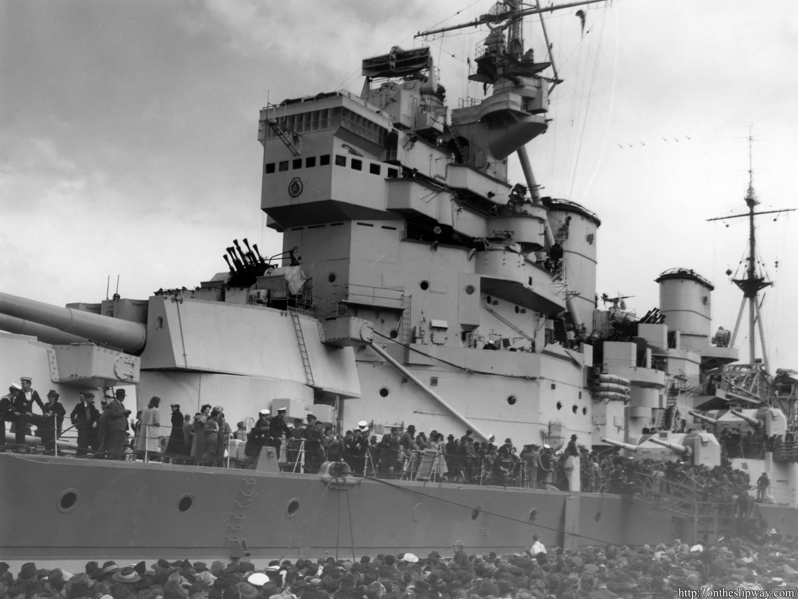
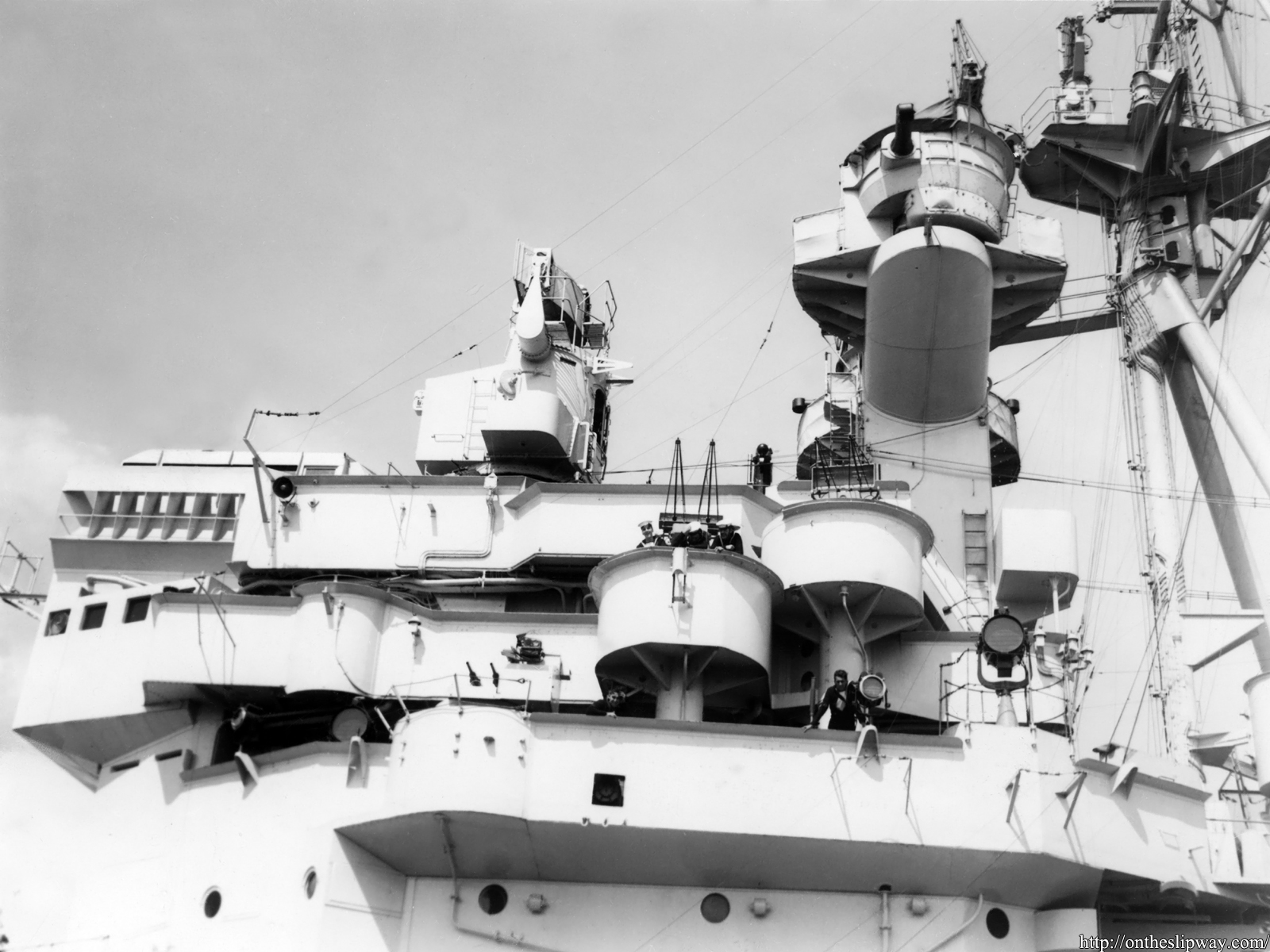
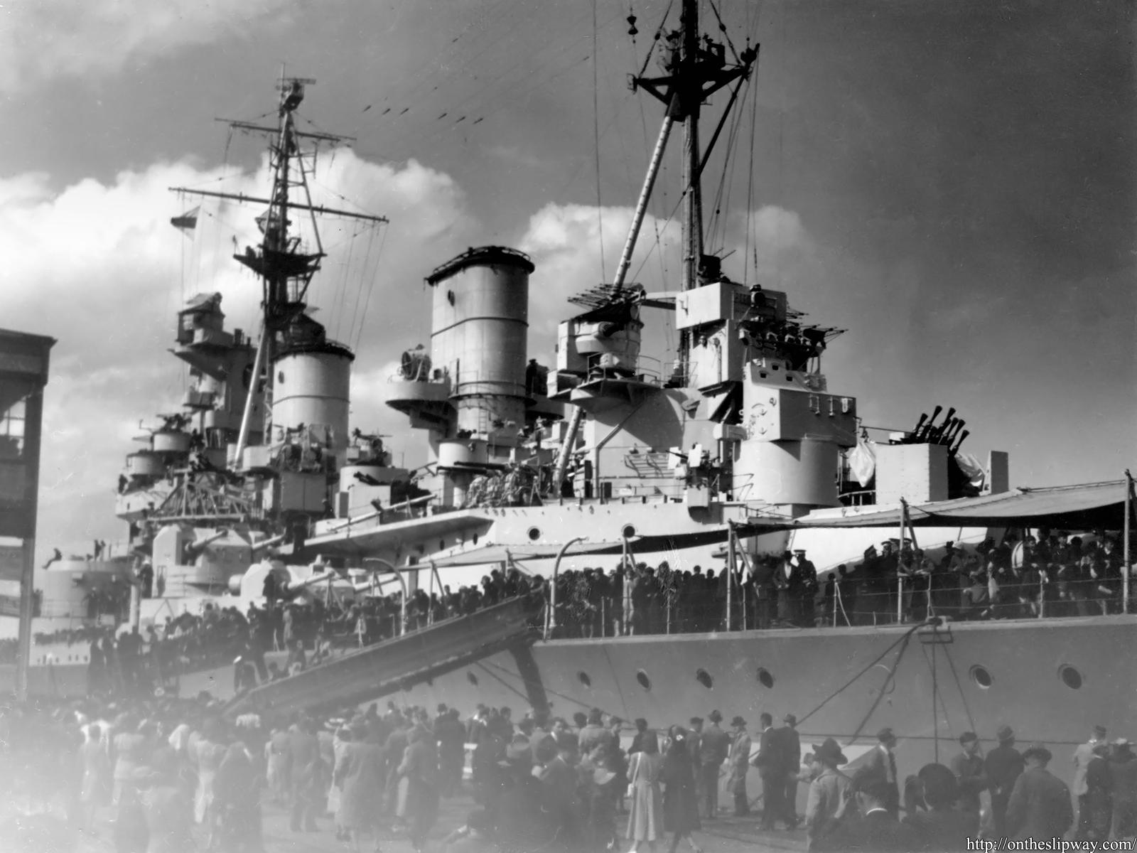
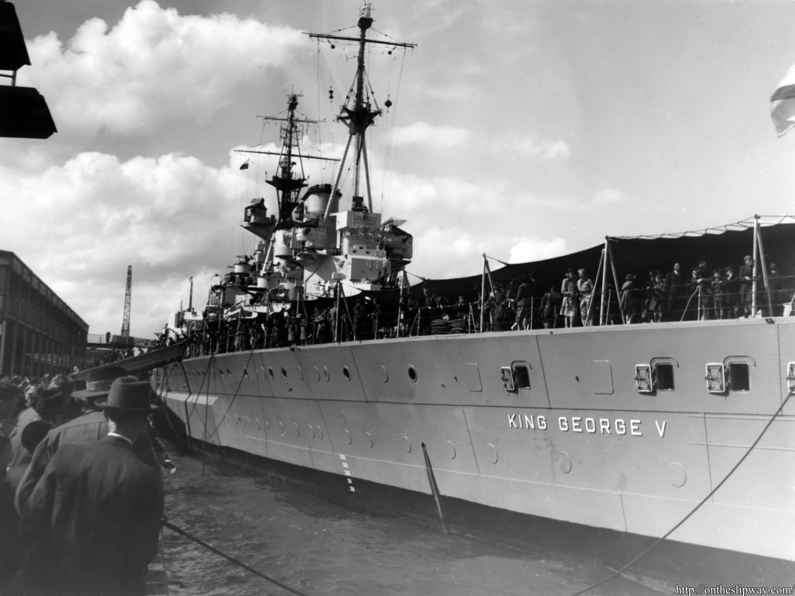
A set of five images of HMS King George V just landed in my mailbox,. As luck would have it, these images complement a set of three I bought a few years earlier but didn’t really tell a story on their own.
The camouflage pattern is an overall light grey and a slightly darker hull, matching the late 1945 pattern (meaning hull/superstructure painted in colours B20/G45), a pattern applied when she was in Australia [1]; the location was easily recognized as Station Pier in Port Melbourne. That puts the (probable) date between the 29th of October and 8th of November, 1945. This is the same period when the famous Allan C. Green photographs were taken, so now we have a collection from the port side well. Although these photographs were not all equally sharp, they do show a very large crowd visiting the ship. A brief search at the Australian War Memorial of HMS King George V’s visit indicates a few more shots taken from similar vantage points and even on board.
[1] Sovereign Hobbies, Royal Navy Camouflage Schemes, HMS King George V